1988 OPEL CALIBRA washer fluid
[x] Cancel search: washer fluidPage 54 of 525
12•40Wiring diagrams
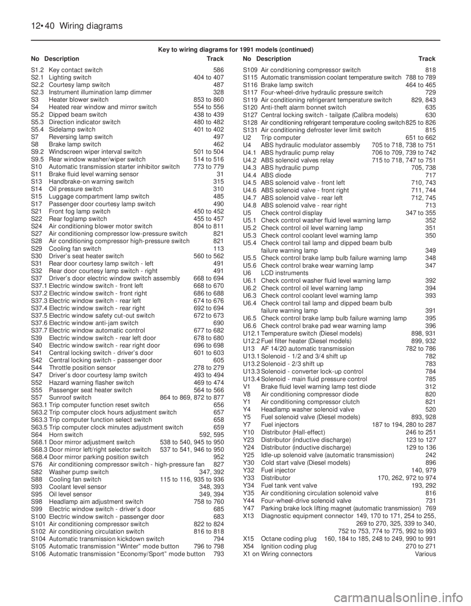
Key to wiring diagrams for 1991 models (continued)
NoDescriptionTrackNoDescriptionTrack
S1.2Key contact switch586
S2.1Lighting switch404 to 407
S2.2Courtesy lamp switch487
S2.3Instrument illumination lamp dimmer328
S3Heater blower switch853 to 860
S4Heated rear window and mirror switch554 to 556
S5.2Dipped beam switch438 to 439
S5.3Direction indicator switch480 to 482
S5.4Sidelamp switch401 to 402
S7Reversing lamp switch497
S8Brake lamp switch462
S9.2Windscreen wiper interval switch501 to 504
S9.5Rear window washer/wiper switch514 to 516
S10Automatic transmission starter inhibitor switch773 to 779
S11Brake fluid level warning sensor31
S13Handbrake-on warning switch315
S14Oil pressure switch310
S15Luggage compartment lamp switch485
S17Passenger door courtesy lamp switch490
S21Front fog lamp switch450 to 452
S22Rear foglamp switch455 to 457
S24Air conditioning blower motor switch804 to 811
S27Air conditioning compressor low-pressure switch821
S28Air conditioning compressor high-pressure switch821
S29Cooling fan switch113
S30Driver’s seat heater switch560 to 562
S31Rear door courtesy lamp switch - left491
S32Rear door courtesy lamp switch - right491
S37Driver’s door electric window switch assembly668 to 694
S37.1Electric window switch - front left668 to 670
S37.2Electric window switch - front right686 to 688
S37.3Electric window switch - rear left674 to 676
S37.4Electric window switch - rear right692 to 694
S37.5Electric window safety cut-out switch672 to 673
S37.6Electric window anti-jam switch690
S37.7Electric window automatic control677 to 682
S39Electric window switch - rear left door678 to 680
S40Electric window switch - rear right door696 to 698
S41Central locking switch - driver’s door601 to 603
S42Central locking switch - passenger door605
S44Throttle position sensor278 to 279
S47Driver’s door courtesy lamp switch493 to 494
S52Hazard warning flasher switch469 to 474
S55Passenger seat heater switch564 to 566
S57Sunroof switch864 to 869, 872 to 877
S63.1Trip computer function reset switch656
S63.2Trip computer clock hours adjustment switch657
S63.3Trip computer function select switch658
S63.5Trip computer clock minutes adjustment switch659
S64Horn switch592, 595
S68.1Door mirror adjustment switch538 to 540, 945 to 950
S68.3Door mirror left/right selector switch537 to 541, 946 to 950
S68.4Door mirror parking position switch952
S76Air conditioning compressor switch - high-pressure fan827
S82Washer pump switch347, 392
S88Cooling fan switch115 to 116, 935 to 936
S93Coolant level sensor348, 393
S95Oil level sensor349, 394
S98Headlamp aim adjustment switch758 to 760
S99Electric window switch - driver’s door685
S100Electric window switch - passenger door683
S101Air conditioning compressor switch822 to 824
S102Air conditioning circulation switch816 to 818
S104Automatic transmission kickdown switch794
S105Automatic transmission “Winter” mode button796 to 798
S106Automatic transmission “Economy/Sport” mode button793S109Air conditioning compressor switch818
S115Automatic transmission coolant temperature switch788 to 789
S116Brake lamp switch464 to 465
S117Four-wheel-drive hydraulic pressure switch729
S119Air conditioning refrigerant temperature switch829, 843
S120Anti-theft alarm bonnet switch635
S127Central locking switch - tailgate (Calibra models)630
S128Air conditioning refrigerant temperature cooling switch825 to 826
S131Air conditioning defroster lever limit switch815
U2Trip computer651 to 662
U4ABS hydraulic modulator assembly705 to 718, 738 to 751
U4.1ABS hydraulic pump relay706 to 709, 739 to 742
U4.2ABS solenoid valves relay715 to 718, 747 to 751
U4.3ABS hydraulic pump705, 738
U4.4ABS diode717
U4.5ABS solenoid valve - front left710, 743
U4.6ABS solenoid valve - front right711, 744
U4.7ABS solenoid valve - rear left712, 745
U4.8ABS solenoid valve - rear right713
U5Check control display347 to 355
U5.1Check control washer fluid level warning lamp352
U5.2Check control oil level warning lamp351
U5.3Check control coolant level warning lamp350
U5.4Check control tail lamp and dipped beam bulb
failure warning lamp349
U5.5Check control brake lamp bulb failure warning lamp348
U5.6Check control brake wear warning lamp347
U6LCD instruments
U6.1Check control washer fluid level warning lamp392
U6.2Check control oil level warning lamp394
U6.3Check control coolant level warning lamp393
U6.4Check control tail lamp and dipped beam bulb
failure warning lamp391
U6.5Check control brake lamp bulb failure warning lamp395
U6.6Check control brake pad wear warning lamp396
U12.1Temperature switch (Diesel models)898, 931
U12.2Fuel filter heater (Diesel models)899, 932
U13AF14/20automatic transmission782 to 786
U13.1Solenoid - 1/2 and 3/4 shift up782
U13.2Solenoid - 2/3 shift up783
U13.3Solenoid - converter lock-up control784
U13.4Solenoid - main fluid pressure control785
V1Brake fluid level warning lamp test diode312
V8Air conditioning compressor diode820
Y1Air conditioning compressor clutch821
Y4Headlamp washer solenoid valve520
Y5Fuel solenoid valve (Diesel models)893, 928
Y7Fuel injectors187 to 194, 280 to 287
Y10Distributor (Hall-effect)246 to 251
Y23Distributor (inductive discharge)123 to 127
Y24Distributor (inductive discharge)129 to 136
Y25Idle-up solenoid valve (automatic transmission)242
Y30Cold start valve (Diesel models)896
Y32Fuel injector140, 979
Y33Distributor170, 262, 972 to 974
Y34Fuel tank vent valve193, 292
Y35Air conditioning circulation solenoid valve816
Y44Four-wheel-drive solenoid valve731
Y47Parking brake lock lifting magnet (automatic transmission)769
X13Diagnostic equipment connector149, 170 to 171, 254 to 255,
269 to 270, 325, 339 to 340,
752 to 753, 774 to 775, 992 to 993
X15Octane coding plug160, 184 to 185, 248 to 249, 990 to 991
X54Ignition coding plug270 to 271
X1 onWiring connectorsVarious
Page 69 of 525

Wiring diagrams 12•55
12
Key to wiring diagrams for 1992 and later models
NoDescriptionTrackNoDescriptionTrack
E1Left parking lamp506
E2Left tail lamp507, 745
E3Licence plate lamp513
E4Right parking lamp509
E5Right tail lamp510, 746
E6Engine compartment lamp515
E7Left high beam 535
E8Right high beam536
E9Left low beam537, 747
E10Right low beam538, 748
E11Instrument lights728, 729
E12Selector lever lamp 498, 499
E13Boot lamp585
E14Passenger compartment lamp587
E15Glove box lamp677
E16Cigarette lighter lamp676
E17Left reversing lamp597
E18Right reversing lamp598
E19Heated back window652
E20Left fog lamp553
E21Right fog lamp554
E24Left rear fog lamp548
E25Left front heating mat660
E27Left rear reading lamp680, 681
E28Right rear reading lamp683, 684
E30Right front heating mat664
E32Clock lamp863
E37Left mirror make-up lamp686
E38Computer lamp854
E39Right rear foglamp549
E40Right mirror make-up lamp688
E41Passenger compartment delay lamp 588 to 590
E50Driver door lamp866
E51Passenger door lamp884
F1 onFusesVarious
F35Voltage stabilizer702
G1Battery101
G2Alternator114
G6Diesel alternator 402 to 405
H1Radio784 to 798
H3Turn signal lamp telltale716, 718
H4Oil pressure telltale710
H5Brake fluid telltale712
H6Telltale hazard warning system570
H7Charging indicator lamp710
H8High beam telltale722
H9Left stop lamp561, 749
H10Right stop lamp562, 750
H11Left front turn signal lamp572
H12Left rear turn signal lamp573
H13Right front turn signal lamp581
H14Right rear turn signal lamp582
H15Fuel telltale705, 706
H16Preheating time telltale715
H17Trailer turn signal lamp telltale717
H18Horn670
H19Headlamps on warning buzzer594, 595
H21Parking brake telltale713
H23Airbag telltale719
H25Heated back window & mirror telltale642, 765
H26ABS telltale721
H27Safety checking warning buzzer996 to 998
H28Seat belt warning telltale723
H30Engine telltale724H33Left auxiliary turn signal lamp576
H34Right auxiliary turn signal lamp578
H36Additional stop lamp563
H37Left front loudspeaker788 to 790
H38Right front loudspeaker794 to 796
H39Left rear loudspeaker788, 789
H40Right rear loudspeaker791, 792
H42Automatic program power telltale725
H45Four wheel drive telltale727
H46Catalytic converter temperature telltale729
H47Anti-theft warning unit horn838
H48Horn671
H51Traction control telltale720
H52Left front tweeter787 to 791
H53Right front tweeter793 to 797
K3Starter relay anti-theft warning unit109, 110
K5Fog lamps relay554 to 555
K6Air conditioning relay901, 902
K7Four stage air conditioning blower relay904, 905
K8Windshield wiper interval relay603 to 606
K9Headlamps washer unit relay619, 620
K10Flasher unit567 to 569
K20Ignition coil module149, 150, 171, 172, 241, 242, 302 to 305,
361 to 364, 1001 to 1005, 1055 to 1061
K22Coolant pump relay133, 134, 969, 970
K25Glow time relay440 to 443
K26Radiator blower relays972 to 974
K27Radiator blower relay137 to 139
K30Back window wiper interval relay613 to 615
K31Airbag control unit1191 to 1198
K34Radiator blower time delay relay356 to 358, 956 to 958
K35Heated back window & mirror time delay relay650 to 652
K37Central locking control unit805 to 812
K51Radiator blower relay430, 431, 942, 943, 956, 957
K52Radiator blower relay145 to 147, 433,435,
982 to 984, 960 to 962
K57Multec unit control211 to 230, 244 to 262
K58Fuel pump relay231, 232, 262, 263
K59Running light relay520 to 525
K60Compressor relay931,932
K61Motronic control unit270 to 294, 307 to 337,
366 to 396, 1007 to 1037, 1063 to 1096
K63Horn relay671, 672
K641 stage air conditioning blower relay913, 914
K67Radiator blower relay142, 143, 436, 437, 948,
949, 964, 965, 986, 987
K68Fuel injection unit relay295 to 299, 393 to 397,
334 to 338, 1093 to 1097, 1034 to 1038
K73High beam relay (Calibra)530, 531
K76Glow time control unit413 to 417
K77Glow plugs relay419, 420
K78Preresistor relay (70A)422, 423
K79Charge indicator relay406 to 408
K80Filter heating relay426, 427, 452, 453
K82Engine revolution relay447, 448
K83Four wheel drive unit control342 to 349
K84EZ Plus control unit155 to 166, 177 to 191
K85Automatic transmission control unit473 to 496
K86Check control unit736 to 752
K87Radiator blower relay945, 946, 953, 954, 977, 978
K88Catalytic converter temperature control unit462 to 464
K89Rear fog lamp relay543 to 545
K90Compressor relay (automatic transmission only)930, 931
K94Anti-theft warning unit control unit833 to 847
Page 70 of 525

12•56Wiring diagrams
Key to wiring diagrams for 1992 and later models (continued)
NoDescriptionTrackNoDescriptionTrack
K95Traction control control unit1125 to 1140
K97Headlamps washer pump time delay relay630 to 632
K101Parking position mirror relay774 to 777
K102Park brake shift lock control unit 469 to 471
L1Ignition coil150, 172, 205, 273, 241, 302, 361
L2Ignition coil1000 to 1004, 1054 to 1059
M1Starter105, 106
M2Windshield wiper motor601 to 604
M3Heating blower motor127 to 129
M4Radiator blower motor118, 120, 140, 356, 431, 948, 954, 980
M6Left headlamp wiper motor622 to 624
M7Right headlamp wiper motor 626 to 628
M8Back window wiper motor611 to 613
M10Air conditioning blower motor905 to 908
M11Radiator blower motor136, 434, 962, 984
M13Vectra/Cavalier sun roof motor1172 to 1175
M13.1Sun roof motor1172, 1174
M13.2Timing box microswitch1172
M13.3Timing box microswitch1174
M18Driver door central locking motor807 to 810
M19Left rear door central locking motor821 to 823
M20Right rear door central locking motor825 to 827
M21Fuel pump232, 263, 297, 339, 399, 834, 1098, 1039
M23Alternator blower motor135, 974
M24Headlamps washer pump632
M26Automatic antenna motor798 to 799
M30Driver side outside mirror638 to 641
M31Passenger side outside mirror644 to 647
M32Passenger door central locking motor813 to 816
M33Idle speed actuator285, 286, 317, 318, 381,
382, 1019, 1020, 1075, 1076
M37Tail gate/boot lid central locking motor818 to 821
M39Left headlamp levelling motor 692 to 695
M40Right headlamp levelling motor696 to 699
M41Fuel filler door central locking motor823, 824
M47Driver door window lifter motor867 to 871
M48Passenger door window lifter motor885 to 889
M49Left rear window lifter motor873 to 877
M50Right rear window lifter motor891 to 895
M55Windshield and back window washer pump617
M57Coolant pump134, 970
M60Calibra tailgate central locking motor827, 828
M61Calibra sun roof motor1178 to 1186
M61.1Sun roof motor1179 to 1182
M61.2Relay 11178, 1179
M61.3Relay 21184 to 1186
M62Driver side outside mirror760 to 767
M63Passenger side outside mirror769 to 776
M65TC throttle valve actuator1130 to 1134
M66Idle air stepper motor215 to 218, 250 to 253
P1Fuel indicator704
P2Coolant temperature indicator706
P3Clock862
P4Fuel sensor704
P5Coolant temperature sensor706
P7Tachometer708
P11Airflow meter 285 to 289
P12Coolant temperature sensor282, 381
P13Outside temperature sensor856
P14Distance sensor412, 413
P17Left front revolution sensor1110, 1154
P18Right front revolution sensor1113, 1157
P19Left rear revolution sensor1116, 1160
P20Right rear revolution sensor1119, 1163P21Distance sensor731
P23Intake manifold absolute pressure sensor160, 161, 185, 186,
217 to 219, 250 to 252
P24Engine oil temperature sensor162, 187
P27Left front brake lining sensor740
P28Right front brake lining sensor740
P29Intake manifold temperature sensor382, 1016, 1072
P30Coolant temperature sensor215, 248, 313, 1017, 1073
P32Heated exhaust oxygen sensor294, 295, 331, 332, 391,
392, 1034, 1035, 1093, 1094
P33Exhaust oxygen sensor229, 257
P34Throttle valve potentiometer221 to 223, 280, 281, 253 to 255,
383 to 385, 478, 479, 1018, 1019, 1074, 1075
P35Crankshaft impulse sensor178 to 180, 289 to 291, 248 to 250,
318 to 320, 373 to 375, 1025 to 1027, 1084 to 1086
P38Transmission oil temperature sensor494
P39Trailer bulb test sensor752 to 754
P43Electronic speedometer733
P44Air mass meter393 to 397, 334 to 338,
1037, 1038, 1096, 1097
P45Transmission input revolution sensor490, 491
P46Knock control sensor322, 323, 377, 378,
1022, 1023, 1078, 1079
P47Cylinder identification hall sensor325 to 327, 385 to 387,
1028 to 1030, 1087, 1089
P48Automatic transmission distance sensor488, 489
P50Catalytic converter temperature sensor463, 464
P53Driver side anti-theft warning unit sensor839 to 847
P54Passenger side anti-theft warning unit sensor839 to 847
P55Engine coolant temperature sensor415
P56Knock control sensor II1080, 1081
P57Antenna797
R3Cigarette lighter675
R5Glow plugs418 to 420, 441 to 443
R13Left heated washer nozzle 626
R14Right heated washer nozzle628
R19Radiator blower preresistor120, 140, 945
R22Glow plugs pre-resistor423
R23Driver airbag squib1194
S1Starter switch103 to 106
S1.2Key contact switch783
S2Light switch assy
S2.1Light switch504 to 507
S2.2Passenger compartment lamp switch587
S2.3Instrument lights dimmer728
S3Heating blower switch123 to 130
S4Heated back window & mirror switch654 to 657
S5Turn signal switch assy
S5.2Low beam switch536, 537
S5.3Turn signal switch580 to 582
S5.4Parking lamp switch501, 502
S7Back up lamp switch597, 599
S8Stop lamp switch562
S9Wiper unit switch
S9.2Interval windshield wiper switch601 to 604
S9.5Back window and washer unit wiper switch614 to 616
S10Automatic transmission switch472 to 478
S11Brake fluid control switch712
S13Parking brake switch713
S14Oil pressure switch710
S15Boot lamp switch585
S17Passenger door contact switch590
S20Pressure switch
S20.1Low pressure compressor switch925
Page 71 of 525
Wiring diagrams 12•57
12
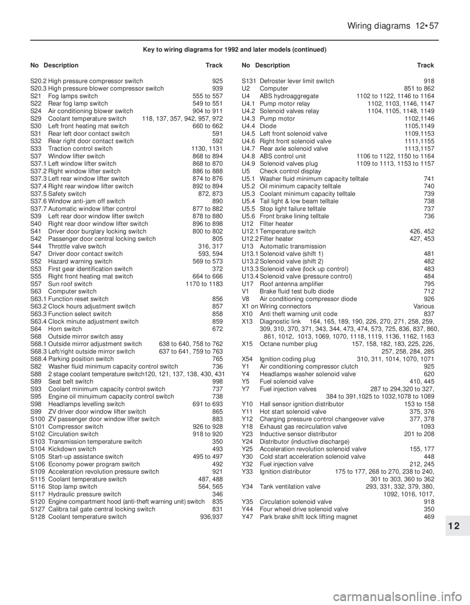
Key to wiring diagrams for 1992 and later models (continued)
NoDescriptionTrackNoDescriptionTrack
S20.2High pressure compressor switch925
S20.3High pressure blower compressor switch939
S21Fog lamps switch555 to 557
S22Rear fog lamp switch549 to 551
S24Air conditioning blower switch904 to 911
S29Coolant temperature switch118, 137, 357, 942, 957, 972
S30Left front heating mat switch660 to 662
S31Rear left door contact switch591
S32Rear right door contact switch592
S33Traction control switch1130, 1131
S37Window lifter switch868 to 894
S37.1Left window lifter switch868 to 870
S37.2Right window lifter switch886 to 888
S37.3Left rear window lifter switch874 to 876
S37.4Right rear window lifter switch892 to 894
S37.5Safety switch872, 873
S37.6Window anti-jam off switch890
S37.7Automatic window lifter control877 to 882
S39Left rear door window lifter switch878 to 880
S40Right rear door window lifter switch896 to 898
S41Driver door burglary locking switch800 to 802
S42Passenger door central locking switch805
S44Throttle valve switch316, 317
S47Driver door contact switch593, 594
S52Hazard warning switch569 to 573
S53First gear identification switch372
S55Right front heating mat switch664 to 666
S57Sun roof switch1170 to 1183
S63Computer switch
S63.1Function reset switch856
S63.2Clock hours adjustment switch857
S63.3Function select switch858
S63.4Clock minute adjustment switch859
S64Horn switch672
S68Outside mirror switch assy
S68.1Outside mirror adjustment switch638 to 640, 758 to 762
S68.3Left/right outside mirror switch637 to 641, 759 to 763
S68.4Parking position switch765
S82Washer fluid minimum capacity control switch736
S882 stage coolant temperature switch120, 121, 137, 138, 430, 431
S89Seat belt switch998
S93Coolant minimum capacity control switch737
S95Engine oil minuimum capacity control switch738
S98Headlamps levelling switch691 to 693
S99ZV driver door window lifter switch865
S100ZV passenger door window lifter switch883
S101Compressor switch926 to 928
S102Circulation switch918 to 920
S103Transmission temperature switch350
S104Kickdown switch493
S105Start-up assistance switch495 to 497
S106Economy power program switch492
S109Acceleration revolution pressure switch921
S115Coolant temperature switch487, 488
S116Stop lamp switch564, 565
S117Hydraulic pressure switch346
S120Engine compartment hood (anti-theft warning unit) switch835
S127Calibra tail gate central locking switch831
S128Coolant temperature switch936,937S131Defroster lever limit switch918
U2Computer851 to 862
U4ABS hydroaggregate1102 to 1122, 1146 to 1164
U4.1Pump motor relay1102, 1103, 1146, 1147
U4.2Solenoid valves relay1104, 1105, 1148, 1149
U4.3Pump motor1102,1146
U4.4Diode1105,1149
U4.5Left front solenoid valve1109,1153
U4.6Right front solenoid valve1111,1155
U4.7Rear axle solenoid valve1113,1157
U4.8ABS control unit1106 to 1122, 1150 to 1164
U4.9Solenoid valves plug1109 to 1113, 1153 to 1157
U5Check control display
U5.1Washer fluid minimum capacity telltale741
U5.2Oil minimum capacity telltale740
U5.3Coolant minimum capacity telltale739
U5.4Tail light & low beam telltale738
U5.5Stop light failure telltale737
U5.6Front brake lining telltale736
U12Filter heater
U12.1Temperature switch426, 452
U12.2Filter heater427, 453
U13Automatic transmission
U13.1Solenoid valve (shift 1)481
U13.2Solenoid valve (shift 2)482
U13.3Solenoid valve (lock up control)483
U13.4Solenoid valve (pressure control)484
U17Roof antenna amplifier795
V1Brake fluid test bulb diode712
V8Air conditioning compressor diode926
X1 onWiring connectorsVarious
X10Anti theft warning unit code837
X13Diagnostic link164, 165, 189, 190, 226, 270, 271, 258, 259,
309, 310, 370, 371, 343, 344, 473, 474, 573, 725, 836, 837, 860,
861, 1012, 1013, 1069, 1070, 1118, 1119, 1136, 1162, 1163
X15Octane number plug157, 158, 182, 183, 225, 226,
257, 258, 284, 285
X54Ignition coding plug310, 311, 1014, 1070, 1071
Y1Air conditioning compressor clutch925
Y4Headlamps washer solenoid valve620
Y5Fuel solenoid valve410, 445
Y7Fuel injection valves287 to 294,320 to 327,
384 to 391,1025 to 1032,1078 to 1089
Y10Hall sensor ignition distributor153 to 158
Y11Hot start solenoid valve375, 376
Y12Charging pressure control changeover valve377, 378
Y18Exhaust gas recirculation valve1093
Y23Inductive sensor distributor201 to 208
Y24Distributor (inductive discharge)
Y25Acceleration revolution solenoid valve155, 177
Y30Cold start acceleration solenoid valve 448
Y32Fuel injection valve212, 245
Y33Ignition distributor175 to 177, 268 to 270, 238 to 240,
301 to 303, 360 to 362
Y34Tank ventilation valve293, 331, 332, 379, 380,
1092, 1016, 1017,
Y35Circulation solenoid valve918
Y44Four wheel drive solenoid valve350
Y47Park brake shift lock lifting magnet469
Page 107 of 525
6Bonnet - removal and refitting
2
Removal
1Open the bonnet, and support it in the fully
open position.
2On models fitted with an underbonnet lamp,
disconnect the battery negative lead, then
prise the lamp from the bonnet and disconnect
the wiring. If the bonnet is to be refitted, to aid
routing of the wiring on refitting, tie a length of
string to the end of the wiring. Then withdraw
the wiring through the bonnet and untie the
string, leaving it in position in the bonnet.
3Similarly, disconnect the windscreen
washer fluid hose from the connector in the
bonnet, but tie the string to the connector, to
prevent it from slipping into an inaccessible
position in the bonnet.
4Mark the position of the hinges on the
bonnet.
5With the help of an assistant, support the
weight of the bonnet, then unscrew the
securing bolts from the hinges, and lift the
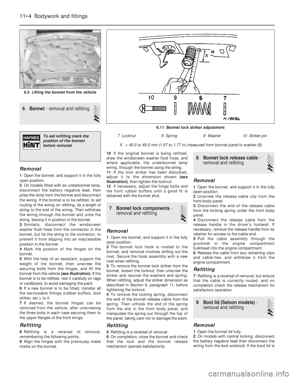
bonnet from the vehicle (see illustration). If the
bonnet is to be refitted, rest it carefully on rags
or cardboard, to avoid damaging the paint.
6If a new bonnet is to be fitted, transfer all
the serviceable fittings (rubber buffers, lock
striker, etc.), to it.
7If desired, the bonnet hinges can be
removed from the vehicle, after unscrewing
the three bolts in each case securing them to
the upper flanges of the front wings.
Refitting
8Refitting is a reversal of removal,
remembering the following points.
9Align the hinges with the previously made
marks on the bonnet.10If the original bonnet is being refitted,
draw the windscreen washer fluid hose, and
where applicable, the underbonnet lamp
wiring, through the bonnet using the string.
11If the lock striker has been disturbed,
adjust it to the dimension shown (see
illustration), then tighten the locknut.
12If necessary, adjust the hinge bolts and
the front rubber buffers until a good fit is
obtained with the bonnet shut.
7Bonnet lock components -
removal and refitting
2
Removal
1Open the bonnet, and support it in the fully
open position.
2The bonnet lock hook is riveted to the
bonnet, and removal involves drilling out the
rivet. Secure the hook assembly with a new
rivet when refitting.
3To remove the bonnet lock striker from the
bonnet, loosen the locknut, then unscrew the
striker and recover the washers and spring.
When refitting, adjust the striker dimension as
described in Section 6, paragraph 11, before
tightening the locknut.
4To remove the locking spring, disconnect
the end of the bonnet release cable from the
spring. Then unhook the end of the spring
from the slot in the front body panel, and
manipulate the spring out through the top of
the panel, taking care not to damage the paint.
Refitting
5Refitting is a reversal of removal.
6On completion, close the bonnet and check
that the lock and the bonnet release
mechanism operate satisfactorily.
8Bonnet lock release cable -
removal and refitting
2
Removal
1Open the bonnet, and support it in the fully
open position.
2Unscrew the release cable clip from the
front body panel.
3Disconnect the end of the release cable
from the locking spring under the front body
panel.
4Disconnect the release cable from the
release handle in the driver’s footwell. If
necessary, remove the release handle from its
retainer for access to the cable end.
5Pull the cable assembly through the
grommet in the engine compartment
bulkhead into the engine compartment.
6Release the cable from any remaining clips
and cable-ties, and withdraw it from the
engine compartment.
Refitting
7Refitting is a reversal of removal, but ensure
that the cable is correctly routed, and on
completion check the release mechanism for
satisfactory operation.
9Boot lid (Saloon models) -
removal and refitting
2
Removal
1Open the bonnet lid fully.
2On models with central locking, disconnect
the battery negative lead then disconnect the
wiring from the lock solenoid. If the boot lid is
11•4Bodywork and fittings
6.5 Lifting the bonnet from the vehicle
6.11 Bonnet lock striker adjustment
X = 40.0 to 45.0 mm (1.57 to 1.77 in) measured from bonnet panel to washer (9)
7 Locknut8 Spring9 Washer10 Striker pinTo aid refitting mark the
position of the bonnet
before removal.
Page 108 of 525
to be refitted, tie a length of string to the end
of the wiring. Then feed the wiring through the
boot lid and untie the string, leaving it in
position in the boot lid to assist refitting.
3Mark the position of the hinges on the boot
lid.
4With the help of an assistant, support the
weight of the boot lid, then unscrew the
securing bolts from the hinges, and lift the
boot lid from the vehicle. If the boot lid is to be
refitted, rest it carefully on rags or cardboard,
to avoid damaging the paint.
5If a new boot lid is to be fitted, transfer all
the serviceable fittings (rubber buffers, lock
mechanism, etc.), to it.
6If desired, the boot lid hinge counter-
balance springs can be removed, but before
unhooking them from the vehicle body, note
their position so that they can be refitted in
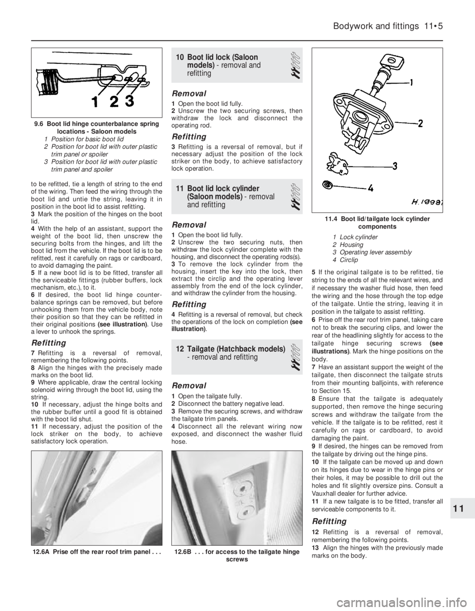
their original positions (see illustration). Use
a lever to unhook the springs.
Refitting
7Refitting is a reversal of removal,
remembering the following points.
8Align the hinges with the precisely made
marks on the boot lid.
9Where applicable, draw the central locking
solenoid wiring through the boot lid, using the
string.
10If necessary, adjust the hinge bolts and
the rubber buffer until a good fit is obtained
with the boot lid shut.
11If necessary, adjust the position of the
lock striker on the body, to achieve
satisfactory lock operation.
10Boot lid lock (Saloon
models) - removal and
refitting
2
Removal
1Open the boot lid fully.
2Unscrew the two securing screws, then
withdraw the lock and disconnect the
operating rod.
Refitting
3Refitting is a reversal of removal, but if
necessary adjust the position of the lock
striker on the body, to achieve satisfactory
lock operation.
11Boot lid lock cylinder
(Saloon models) - removal
and refitting
2
Removal
1Open the boot lid fully.
2Unscrew the two securing nuts, then
withdraw the lock cylinder complete with the
housing, and disconnect the operating rods(s).
3To remove the lock cylinder from the
housing, insert the key into the lock, then
extract the circlip and the operating lever
assembly from the end of the lock cylinder,
and withdraw the cylinder from the housing.
Refitting
4Refitting is a reversal of removal, but check
the operations of the lock on completion (see
illustration).
12Tailgate (Hatchback models)
-removal and refitting
2
Removal
1Open the tailgate fully.
2Disconnect the battery negative lead.
3Remove the securing screws, and withdraw
the tailgate trim panels.
4Disconnect all the relevant wiring now
exposed, and disconnect the washer fluid
hose.5If the original tailgate is to be refitted, tie
string to the ends of all the relevant wires, and
if necessary the washer fluid hose, then feed
the wiring and the hose through the top edge
of the tailgate. Untie the string, leaving it in
position in the tailgate to assist refitting.
6Prise off the rear roof trim panel, taking care
not to break the securing clips, and lower the
rear of the headlining slightly for access to the
tailgate hinge securing screws (see
illustrations). Mark the hinge positions on the
body.
7Have an assistant support the weight of the
tailgate, then disconnect the tailgate struts
from their mounting balljoints, with reference
to Section 15.
8Ensure that the tailgate is adequately
supported, then remove the hinge securing
screws and withdraw the tailgate from the
vehicle. If the tailgate is to be refitted, rest it
carefully on rags or cardboard, to avoid
damaging the paint.
9If desired, the hinges can be removed from
the tailgate by driving out the hinge pins.
10If the tailgate can be moved up and down
on its hinges due to wear in the hinge pins or
their holes, it may be possible to drill out the
holes and fit slightly oversize pins. Consult a
Vauxhall dealer for further advice.
11If a new tailgate is to be fitted, transfer all
serviceable components to it.
Refitting
12Refitting is a reversal of removal,
remembering the following points.
13Align the hinges with the previously made
marks on the body.
Bodywork and fittings 11•5
12.6B . . . for access to the tailgate hinge
screws12.6A Prise off the rear roof trim panel . . .
11.4 Boot lid/tailgate lock cylinder
components
1 Lock cylinder
2 Housing
3 Operating lever assembly
4 Circlip
9.6 Boot lid hinge counterbalance spring
locations - Saloon models
1 Position for basic boot lid
2 Position for boot lid with outer plastic
trim panel or spoiler
3 Position for boot lid with outer plastic
trim panel and spoiler
11
Page 109 of 525
14If the original tailgate is being refitted,
draw the wiring and washer fluid hose (where
applicable) through the tailgate, using the
string.
15If necessary, adjust the hinge bolts and
the rubber buffers, to obtain a good fit when
the tailgate is shut.
16If necessary, adjust the position of the
lock striker on the body, to achieve
satisfactory lock operation.
13Tailgate lock (Hatchback
models) - removal and
refitting
2
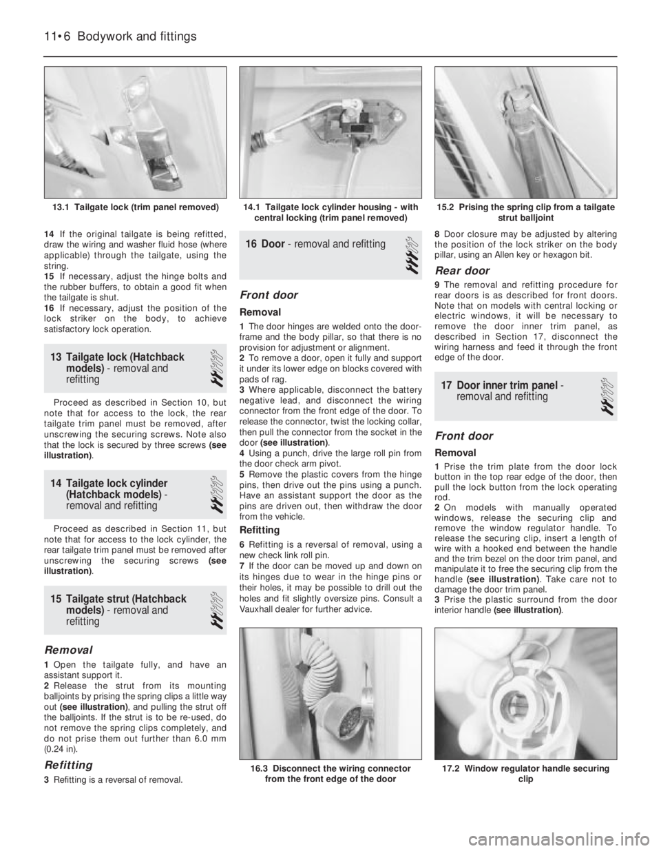
Proceed as described in Section 10, but
note that for access to the lock, the rear
tailgate trim panel must be removed, after
unscrewing the securing screws. Note also
that the lock is secured by three screws (see
illustration).
14Tailgate lock cylinder
(Hatchback models) -
removal and refitting
2
Proceed as described in Section 11, but
note that for access to the lock cylinder, the
rear tailgate trim panel must be removed after
unscrewing the securing screws (see
illustration).
15Tailgate strut (Hatchback
models) - removal and
refitting
2
Removal
1Open the tailgate fully, and have an
assistant support it.
2Release the strut from its mounting
balljoints by prising the spring clips a little way
out (see illustration), and pulling the strut off
the balljoints. If the strut is to be re-used, do
not remove the spring clips completely, and
do not prise them out further than 6.0 mm
(0.24 in).
Refitting
3Refitting is a reversal of removal.
16Door - removal and refitting
3
Front door
Removal
1The door hinges are welded onto the door-
frame and the body pillar, so that there is no
provision for adjustment or alignment.
2To remove a door, open it fully and support
it under its lower edge on blocks covered with
pads of rag.
3Where applicable, disconnect the battery
negative lead, and disconnect the wiring
connector from the front edge of the door. To
release the connector, twist the locking collar,
then pull the connector from the socket in the
door (see illustration).
4Using a punch, drive the large roll pin from
the door check arm pivot.
5Remove the plastic covers from the hinge
pins, then drive out the pins using a punch.
Have an assistant support the door as the
pins are driven out, then withdraw the door
from the vehicle.
Refitting
6Refitting is a reversal of removal, using a
new check link roll pin.
7If the door can be moved up and down on
its hinges due to wear in the hinge pins or
their holes, it may be possible to drill out the
holes and fit slightly oversize pins. Consult a
Vauxhall dealer for further advice.8Door closure may be adjusted by altering
the position of the lock striker on the body
pillar, using an Allen key or hexagon bit.
Rear door
9The removal and refitting procedure for
rear doors is as described for front doors.
Note that on models with central locking or
electric windows, it will be necessary to
remove the door inner trim panel, as
described in Section 17, disconnect the
wiring harness and feed it through the front
edge of the door.
17Door inner trim panel -
removal and refitting
2
Front door
Removal
1Prise the trim plate from the door lock
button in the top rear edge of the door, then
pull the lock button from the lock operating
rod.
2On models with manually operated
windows, release the securing clip and
remove the window regulator handle. To
release the securing clip, insert a length of
wire with a hooked end between the handle
and the trim bezel on the door trim panel, and
manipulate it to free the securing clip from the
handle (see illustration). Take care not to
damage the door trim panel.
3Prise the plastic surround from the door
interior handle (see illustration).
11•6Bodywork and fittings
15.2 Prising the spring clip from a tailgate
strut balljoint
17.2 Window regulator handle securing
clip16.3 Disconnect the wiring connector
from the front edge of the door
14.1 Tailgate lock cylinder housing - with
central locking (trim panel removed)13.1 Tailgate lock (trim panel removed)
Page 115 of 525
6Carefully withdraw the bumper from the
vehicle.
Refitting
7Refitting is a reversal of removal.
Rear bumper
Removal
8Remove the rear trim panel from the
luggage compartment by prising up the top
edge to release the clips, then lift the panel
upwards to free it from the lower locating
tags. The bumper retaining nuts are now
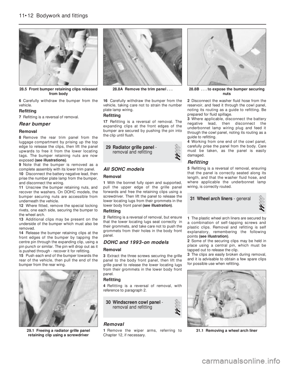
exposed (see illustrations).
9Note that the bumper is removed as a
complete assembly with its lower trim panel.
10Disconnect the battery negative lead, then
prise the number plate lamp from the bumper,
and disconnect the wiring.
11Unscrew the bumper retaining nuts, and
recover the washers. On DOHC models, the
bumper securing nuts are accessible from
underneath the vehicle.
12Where fitted, remove the special locking
rivets, one each side, securing the bumper to
the wheel arch.
13Additional clips may be present on the
underside of the bumper which must also be
removed.
14Release the bumper retaining clips at the
front edges of the bumper by tapping the
centre pin through the expanding clip, using a
pin punch or similar. The pin will drop out as it
is pushed through - recover it for refitting.
15Push each end of the bumper towards the
rear of the vehicle, then pull the end of the
bumper from the rear wing.16Carefully withdraw the bumper from the
vehicle, taking care not to strain the number
plate lamp wiring.
Refitting
17Refitting is a reversal of removal. The
expanding clips at the front edges of the
bumper are secured by pushing the pin into
the clip until flush.
29Radiator grille panel -
removal and refitting
2
All SOHC models
Removal
1With the bonnet fully open and supported,
pull the upper edge of the grille panel
forwards and free the retaining clips using a
screwdriver. Then lift the panel to release the
lower locating lugs from their grommets in the
lower body front panel (see illustration).
Refitting
2Refitting is a reversal of removal, but ensure
that the lower locating lugs seat correctly in
their grommets, and take care not to push the
grommets from their holes in the body front
panel.
DOHC and 1993-on models
Removal
3Extract the three screws securing the grille
panel to the body front panel, then lift the
grille panel to release the lower locating lugs
from their grommets in the lower body front
panel.
Refitting
4Refitting is a reversal of removal, with
reference to paragraph 2.
30Windscreen cowl panel -
removal and refitting
2
Removal
1Remove the wiper arms, referring to
Chapter 12, if necessary.2Disconnect the washer fluid hose from the
reservoir, and feed it through the cowl panel,
noting its routing as a guide to refitting. Be
prepared for fluid spillage.
3Where applicable, disconnect the battery
negative lead, then disconnect the
underbonnet lamp wiring plug and feed it
through the cowl panel, noting its routing as a
guide to refitting.
4Working from one end of the cowl panel,
carefully prise the panel from the body. Care
must be taken, as the panel is easily
damaged.
Refitting
5Refitting is a reversal of removal, ensuring
that the panel is correctly seated along its
length, and that the washer fluid hose, and
where applicable the underbonnet lamp
wiring, is correctly routed.
31Wheel arch liners - general
2
1The plastic wheel arch liners are secured by
a combination of self-tapping screws and
plastic clips. Removal and refitting is self
explanatory, remembering the following
points (see illustration).
2Some of the securing clips may be held in
place using a central pin, which must be
tapped out to release the clip.
3The clips are easily broken during removal,
and it is advisable to obtain a few spare clips
for possible use when refitting.
11•12Bodywork and fittings
28.8B . . . to expose the bumper securing
nuts
31.1 Removing a wheel arch liner29.1 Freeing a radiator grille panel
retaining clip using a screwdriver
28.8A Remove the trim panel . . .28.5 Front bumper retaining clips released
from body