Page 639 of 1378

* PLEASE READ THIS FIRST *
NOTE: Always refer to appropriate engine overhaul article in the
ENGINES section for complete overhaul procedures and
specifications for the vehicle being repaired.
TIMING CHAINS
Timing chains will stretch during operation. Limits are
placed upon amount of stretch before replacement is required. Timing
chain stretch will alter ignition timing and valve timing.
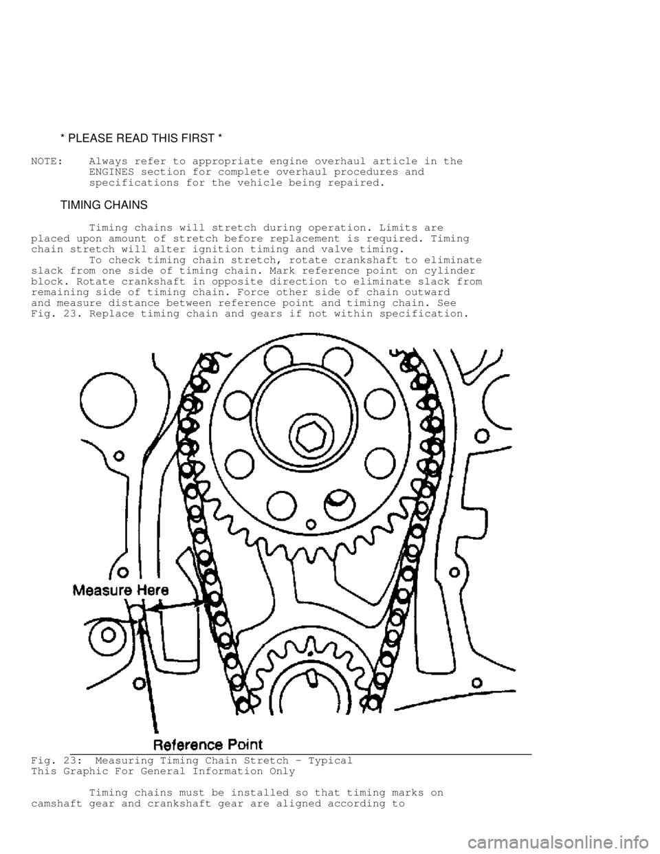
To check timing chain stretch, rotate crankshaft to eliminate
slack from one side of timing chain. Mark reference point on cylinder
block. Rotate crankshaft in opposite direction to eliminate slack from
remaining side of timing chain. Force other side of chain outward
and measure distance between reference point and timing chain. See
Fig. 23 . Replace timing chain and gears if not within specification.
Fig. 23: Measuring Timing Chain Stretch - Typical
This Graphic For General Information Only
Timing chains must be installed so that timing marks on
camshaft gear and crankshaft gear are aligned according to
Page 640 of 1378
manufacturer. See Fig. 24.
Fig. 24: Timing Gear Mark Alignment - Typical
This Graphic For General Information Only
TIMING BELTS
Cogged tooth belts are commonly used on overhead cam
engines. Inspect belt teeth for rounded corners or cracking. Replace
belt if cracked, damaged, missing teeth or oil soaked.
Used timing belt must be installed in original direction of
rotation. Inspect all sprocket teeth for wear. Replace all worn
sprockets. Sprockets are marked for timing purposes. Engine is
positioned so that crankshaft sprocket mark will be upward. Camshaft
sprocket is aligned with reference mark on cylinder head and timing
belt is installed. See Fig. 25.
Page 643 of 1378

* PLEASE READ THIS FIRST *
NOTE: Always refer to appropriate engine overhaul article in the
ENGINES section for complete overhaul procedures and
specifications for the vehicle being repaired.
TIMING GEAR BACKLASH & RUNOUT
On engines where camshaft gear operates directly on
crankshaft gear, gear backlash and runout must be checked. To check
backlash, install dial indicator with tip resting on tooth of camshaft
gear. Rotate camshaft gear as far as possible. Adjust indicator to
zero. Rotate camshaft gear in opposite direction as far as possible
and note reading.
To determine timing gear runout, mount dial indicator with
tip resting on face edge of camshaft gear. Adjust indicator to zero.
Rotate camshaft gear 360 degrees and note reading. If backlash or
runout exceed specifications, replace camshaft and/or crankshaft
gear.
REAR MAIN OIL SEAL
* PLEASE READ THIS FIRST *
NOTE: Always refer to appropriate engine overhaul article in the
ENGINES section for complete overhaul procedures and
specifications for the vehicle being repaired.
INSTALLATION
One-Piece Type Seal
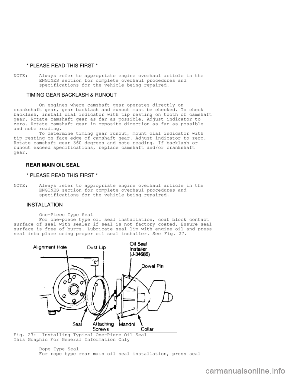
For one-piece type oil seal installation, coat block contact
surface of seal with sealer if seal is not factory coated. Ensure seal
surface is free of burrs. Lubricate seal lip with engine oil and press
seal into place using proper oil seal installer. See Fig. 27.
Fig. 27: Installing Typical One-Piece Oil Seal
This Graphic For General Information Only
Rope Type Seal
For rope type rear main oil seal installation, press seal
Page 644 of 1378
lightly into its seat. Using seal installer, fully seat seal in
bearing cap or cylinder block.
Trim seal ends even with block parting surface. Some
applications require sealer to be applied on main bearing cap prior
to installation. See Fig. 28.
Fig. 28: Typical Rope Seal Installation
This Graphic For General Information Only
Split-Rubber Type Seal
Follow manufacturers procedures when installing split-rubber
type rear main oil seals. Installation procedures vary with engine
type. See appropriate ENGINE article in this section. See Fig. 29.
Fig. 29: Typical Split-Rubber Seal Installation
This Graphic For General Information Only
OIL PUMP
Page 645 of 1378
* PLEASE READ THIS FIRST *
NOTE: Always refer to appropriate engine overhaul article in the
ENGINES section for complete overhaul procedures and
specifications for the vehicle being repaired.
ROTOR-TYPE
Oil pump rotors must be marked for location prior to removal.
See Fig. 30 . Remove outer rotor and measure thickness and diameter.
Measure inner rotor thickness. Inspect shaft for scoring or wear.
Inspect rotors for pitting or damage. Inspect cover for grooving or
wear. Replace components if worn or damaged.
Fig. 30: Typical Rotor Type Oil Pump
This Graphic For General Information Only
Measure outer rotor-to-body clearance. Replace pump assembly
if clearance exceeds specification. Measure clearance between rotors.
See Fig. 31 . Replace shaft and both rotors if clearance exceeds
specifications.
Page 647 of 1378
damaged.
Pump cover wear is measured using a straightedge and feeler
gauge. Pump is to be replaced if warpage or wear exceeds
specifications or mating surface of pump cover is scratched or
grooved.
Fig. 33: Measuring Oil Pump Gear Cavity - Typical
This Graphic For General Information Only
BREAK-IN-PROCEDURE
* PLEASE READ THIS FIRST *
NOTE: Always refer to appropriate engine overhaul article in the
ENGINES section for complete overhaul procedures and
specifications for the vehicle being repaired.
ENGINE PRE-OILING
Engine pre-oiling should be done prior to operation to
prevent engine damage. A lightly oiled pump will cavitate unless oil
pump cavities are filled with engine oil or petroleum jelly.
Page 648 of 1378

Engine pre-oiling can be done using pressure oiler (if
available). Connect pressure oiler to cylinder block oil passage
such as oil pressure sending unit. Operate pressure oiler long enough
to ensure correct amount of oil has filled crankcase. Check oil level
while pre-oiling.
If pressure oiler is not available, disconnect ignition
system. Remove oil pressure sending unit and replace with oil pressure
test gauge. Using starter motor, rotate engine starter until gauge
shows normal oil pressure for several seconds. DO NOT crank engine
for more than 30 seconds to avoid starter motor damage.
Ensure oil pressure has reached the most distant point from
the oil pump. Reinstall oil pressure sending unit. Reconnect ignition
system.
INITIAL START-UP
Start the engine and operate engine at low speed while
checking for coolant, fuel and oil leaks. Stop engine. Recheck coolant
and oil level. Adjust if necessary.
CAMSHAFT
Break-in procedure is required when a new or reground
camshaft has been installed. Operate and maintain engine speed between
1500-2500 RPM for approximately 30 minutes. Procedure may vary due to
manufacturers recommendations.
PISTON RINGS
Piston rings require a break-in procedure to ensure seating
of rings to cylinder walls. Serious damage may occur to rings if
correct procedures are not followed.
Extremely high piston ring temperatures are produced obtained
during break-in process. If rings are exposed to excessively high RPM
or high cylinder pressures, ring damage can occur. Follow piston ring
manufacturer's recommended break-in procedure.
FINAL ADJUSTMENTS
Check or adjust ignition timing and dwell (if applicable).
Adjust valves (if necessary). Adjust carburetion or injection idle
speed and mixture. Retighten cylinder heads (if required). If
cylinder head or block is aluminum, retighten bolts when engine is
cold. Follow the engine manufacturer's recommended break-in procedure
and maintenance schedule for new engines.
NOTE: Some manufacturer's require that head bolts be retightened
after specified amount of operation. This must be done to
prevent head gasket failure.
Page 649 of 1378

\003
EN G IN E R EM OVA L - 4 -C YL
�
1988 J e ep C hero ke e
1988 ENGINES
Jeep - Engine Removal - 4-Cylinder
Cherokee, Comanche, Wrangler
4-CYLINDER ENGINES
2.5L
1) Disconnect negative battery cable. Drain cooling system.
Remove air cleaner, lower radiator hose, fan shroud, and engine
compartment light from hood. Scribe hinge locations and remove hood.
Disconnect automatic transmission cooler lines at radiator (if
equipped).
2) Remove upper radiator hose, fan assembly and coolant
recovery hose. Remove radiator and A/C condenser (if equipped). Hold
fan pulley to water pump flange using 5/16" x 1/2" SAE capscrew.
Disconnect heater hoses, throttle linkages, cruise control cable (if
equipped) and Throttle valve rod.
3) Disconnect wires from starter and separate CEC system
wiring harness connector. Disconnect fuel pipe from fuel pump and fuel
return hose from fuel filter. Disconnect hoses from A/C compressor and
power steering pump (if equipped). Drain power steering pump
reservoir. Cap all fittings and hose ends.
4) Remove vacuum check valve from brake booster (if
equipped). Tag and remove all wiring and vacuum lines connected to
engine or accessories. Raise vehicle and remove starter. Disconnect
exhaust pipe from manifold.
5) Remove converter/flywheel housing cover. Remove engine
mount nuts at bracket side. On automatic transmission models, index
mark drive plate and torque converter. Remove drive plate-to-converter
bolts.
6) Remove upper and loosen lower bellhousing-to-engine bolts.
Attach lifting equipment to engine. Raise engine off front mounts,
Place support under bellhousing. Remove remaining bellhousing-to-
engine bolts. Lift engine out of engine compartment.
NOTE: Engine mount pads may be removed from engine brackets to
align engine and transmission during installation.
TORQUE SPECIFICATIONS
TORQUE SPECIFICATIONS TABLE������������������\
������������������\
������������������\
������������������\
������������������\
������������������\
�����������
Application Ft. Lbs. (N.m)
Clutch Housing-to-Block Bolts .................... 55 (75)
Drive Plate-to-Converter ......................... 26 (35)
Flywheel Bolts ............................... ( 1) 50 (68)
Front Support Bracket-to-Block ................... 45 (61)
Front Support Cushion-to-Crossmember ............. 33 (45)
Rear Support Bracket-to-Transmission ............. 33 (45)
Rear Support Cushion-to-Bracket .................. 30 (41)
Starter Motor-to-Block ........................... 33 (45)
( 1) - Tighten an additional 60 degrees.
������������������\
������������������\
������������������\
������������������\
������������������\
������������������\
�����������