Page 1362 of 1378
Fig. 1: Identifying Tie-Off Symbols
4) If the wires are not drawn all the way to another
component (across several pages), a reference will tell you their
final destination.
5) Again, use the legend on the first page of the wiring
diagram to determine the grid number and letter of the referenced
component. You can then turn directly to it without tracing wires
across several pages.
6) The symbols shown in Fig. 1 are called tie-offs. The first
tie-off shown indicates that the circuit goes to the temperature
sensor, and is also a ground circuit.
7) The second symbol indicates that the circuit goes to a
battery positive parallel circuit. The third symbol leads to a
particular component and the location is also given.
8) The lines shown in Fig. 2 are called options. Which path
or option to take depends on what engine or systems the vehicle has.
Page 1369 of 1378

WIR IN G D IA G RAM S
�
1988 J e ep C hero ke e
1988 Wiring Diagrams
Jeep
Cherokee & Wagoneer
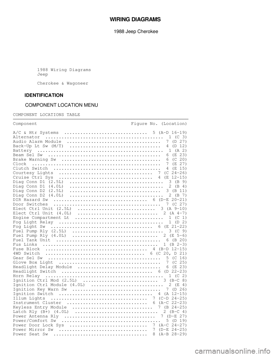
IDENTIFICATION
COMPONENT LOCATION MENU
COMPONENT LOCATIONS TABLE������������������\
������������������\
������������������\
������������������\
������������������\
������������������\
������������������\
���
Component Figure No. (Location)
A/C & Htr Systems ............................... 5 (A-D 16-19)
Alternator ............................................ 1 (C 3)
Audio Alarm Module ................................... 7 (D 27)
Back-Up Lt Sw (M/T) .................................. 4 (D 12)
Battery ............................................... 1 (A 2)
Beam Sel Sw .......................................... 6 (E 23)
Brake Warning Sw ..................................... 6 (C 20)
Clock ................................................ 7 (E 27)
Clutch Switch ........................................ 4 (E 15)
Courtesy Lights ................................... 7 (C 24-26)
Cruise Ctrl Sys ................................... 4 (E 12-15)
Diag Conn D1 (2.5L) ................................... 3 (B 9)
Diag Conn D1 (4.0L) ................................... 2 (B 4)
Diag Conn D2 (2.5L) .................................. 3 (B 11)
Diag Conn D2 (4.0L) ................................... 2 (B 7)
DIR Hazard Sw ................................... 6 (D-E 20-21)
Door Switches ........................................ 7 (C 27)
Elect Ctrl Unit (2.5L) ............................. 3 (A 9-10)
Elect Ctrl Unit (4.0L) .............................. 2 (A 4-7)
Engine Compartment Lt ................................. 1 (C 1)
Fog Light Relay ....................................... 1 (D 2)
Fog Light Sw ...................................... 6 (E 21-22)
Fuel Pump Rly (2.5L) .................................. 3 (C 9)
Fuel Pump Rly (4.0L) ................................ 2 (E 5-6)
Fuel Tank Unit ....................................... 6 (B 20)
Fus Links ........................................... 1 (B 2-3)
Fuse Block ...................................... 4 (B-D 12-15)
4WD Switch ..................................... 6 (C 20, D 21)
Gear Sel Sw .......................................... 5 (C 16)
Glove Box Light ...................................... 7 (C 25)
Headlight Delay Module ............................... 6 (E 23)
Headlight Switch .................................. 6 (D 22-23)
Horn Relay ............................................ 1 (C 2)
Ignition Ctrl Mod (2.5L) ............................ 3 (B-C 8)
Ignition Ctrl Module (4.0L) ........................... 2 (E 4)
Ignition Key Warn Sw ................................. 7 (D 26)
Ignition Switch ................................... 4 (A 12-15)
Illum Lights .................................... 7 (C-D 24-25)
Instrument Cluster .............................. 6 (A-C 22-23)
Keyless Entry Module .............................. 7 (B 24-25)
Latch Rly (B+) (4.0L) ............................... 2 (B-C 4)
Power Antenna Rly .................................. 7 (D-E 27)
Power/Comfort Sw ..................................... 5 (D 19)
Power Door Lock Sys ............................. 7 (A-C 24-27)
Power Mirror Sw ................................. 7 (D-E 24-25)
Power Seat Sw ................................... 8 (A-B 28-29)
Page 1371 of 1378
Fig. 1: Engine Compartment & Headlights
Page 1372 of 1378
Fig. 2: Computer Engine Control (6-Cyl)
Page 1373 of 1378
Fig. 3: Computer Engine Control (4-Cyl)