1988 FIAT TEMPRA brake
[x] Cancel search: brakePage 55 of 171

REAR SHOCK ABSORBERS • Job 48. Check wheel bolts for tightness.
Look for signs of leaks coming from underneath the top part
of
each
rear shock absorber and replace if necessary. Check
the
top and bottom rubber mounting bushes. If any are soft
or
split they must be replaced. Check that the bump stops are
present and correct.
BOUNCE TEST: Bounce-test the shock absorbers as in Job 43.
PART G: BRAKING SYSTEM
SAFETY FIRST!
• Job 49. Check front brakes.
You can
check the thickness of the brake pads by looking
through
the 'window' in the caliper. However, this isn't
recommended
unless you are experienced and know what you
are looking for,
and you can't check the caliper or clean out
accumulated
brake dust.
• Before raising the car, see Chapter 1, Safety First!
•
Also,
be sure to read the section on BRAKES AND
ASBESTOS in Chapter 1, Safety First! for further
important
information.
•
Your car's
brakes are its most important
safety-
related items.
Do NOT attempt any work on the
braking system unless
you are fully competent to do so.
• If you have not been trained in this work, but wish
to
carry
it out, we strongly recommend you have a
garage
or qualified mechanic check your work before
using
the car on the road.
•
Always
start by washing the brakes with a propri-
etary
brand of brake cleaner
-
brake drums removed
where
appropriate
-
and never use compressed air to
clean
off
brake
dust.
•
Always
replace brake pads and/or shoes in complete
'axle' sets
of four
-
never replace them on one wheel
only.
• After fitting new brake shoes or pads, avoid heavy
braking
for the first
150
to 200 miles (250 to 300 km),
except
in
an emergency.
49B. This
drawing
illustrates the
various
components of
the front brake
assembly.
49C. Remove the
bottom caliper bolt,
using an open-ended
spanner to allow the
bolt to turn. ALWAYS
refit with NEW FIAT
caliper mounting bolts
-
they are a special
type.
Therefore,
checking the Tipo's and Tempra's brake pads
involves
the same amount of work as changing them. For that
reason, brake
pad replacement is covered here in detail rather
than in
Chapter
6,
Repairs and Replacements.
49A. Start by raising
the
wheel to
be
worked on and
supporting it on
an
axle stand. Remove
the road wheel
-
see
Chapter
1, Safety
First!
Compare the thickness of the two pads
-
there should be no
significant difference. The minimum recommended thickness
of lining material is 1.5 mm, but bearing in mind the amount
of time before the next service, you may wish to replace the
pads before they get to this stage.
You can now check the thickness of the brake disc, which
should not be below the figure given for your model in
Chapter
3,
Facts and Figures, at any point.
Remove each wheel
bolt in turn and
ensure that they run
smoothly. Clean the
threads, if necessary.
Refit and check that all
are tightened to the
correct torque
-
see
Chapter
3,
Facts and
Figures
-
using a torque wrench.
49D. Slacken the top
bolt, swivel the caliper
up and the pads come
free, for checking.
IMPORTANT NOTE:
If you remove the
top caliper bolt, DO NOT allow the weight of the caliper
to hang from the flexible hose
-
position it to rest on the
driveshaft, or support it from the road spring using a
length of wire.
Page 56 of 171

49H. ...and push out the nylon bush (arrowed). Reassemble
on the new pad and reattach the wire.
IMPORTANT NOTE: After fitting the pads, apply the
brakes firmly several times to adjust them.
• Job 50. Check rear brakes.
SAFETY FIRST!
Read SAFETY FIRST at the start of Job 49 before
proceeding!
GENERAL. The majority of Tipo/Tempra models are fitted with
rear drum-type rear brakes, but models with ABS anti-lock
braking have a disc-and-caliper arrangement instead.
Slacken the wheel bolts, raise the wheel, remove it and
support the car with an axle stand. Make sure that the wheels
remaining on the ground are chocked in both directions and
that the handbrake is off.
DRUM REAR BRAKES
If the drum
sticks,
try:
• screwing a pair of
bolts
into the two threaded
holes in the drum. Evenly
tightening the bolts will force the drum off the
shoes.
• tapping carefully around the drum with a hide
mallet to help loosen it.
s Vn order to fit new pads,
r> - the caliper piston must be
pushed back into the bore.
• Use an old battery hydrometer to draw about half
of the fluid from the master cylinder.
• Push the piston back into the caliper, using a G-
clamp.
• Keep an eye on the master cylinder so that it
doesn't overflow as fluid is pushed back up the pipe.
IMPORTANT NOTE: Be very sparing or grease could
migrate to the friction linings!
WEAR SENSORS I I There are certain essential checks you
should carry out for yourself, with brake
pads removed:
• Look for any obvious grooves worn into the disc.
Slight undulations are acceptable, but anything worse
and the disc should be replaced.
• Look and feel for any wear-ridge on the outer edges
of the disc. The depth will give an indication of wear.
• Check for corrosion of the disc surface. If any is
found, the brake caliper is probably faulty, and needs
checking.
• If any surface flaking is found on either side of the
disc, replace them both.
• If you are not certain whether any wear is acceptable,
ask your specialist or FIAT dealer to check.
FACT FILE: BRAKE DISC WEAR
SYMPTOMS
Before reassembling the brake, check the condition of the
brake caliper. Have an assistant VERY SLOWLY AND GENTLY
apply pressure to the brake pedal while you watch the piston
(see illustration 49B, part
8),
which should move outwards. If
it doesn't easily move, it is seized and the caliper should be
replaced. DO NOT allow the piston to project more than 10
mm or it may be forced from the caliper
-
use a G-clamp as an
'end stop'.
49F. Before
fitting the pads,
put a light smear
of brake grease
(NOT ordinary
grease) on the
pads' metal
backplates at the
points shown.
49G. If these are fitted, the contact has to be transferred from
the old backing plate to the new. Pull off the wire, push out
the brass pin...
49E. Check inside
the caliper housing
for signs of
corrosion. If any is
found, or the seal is
damaged, the caliper
should be exchanged
for a new or
overhauled unit from
your FIAT dealership.
Examine the piston's protective gaiter (see illustration 49B,
part 9) for splitting and fluid leaks. This one is in poor
condition and the caliper requires immediate replacement.
Page 57 of 171
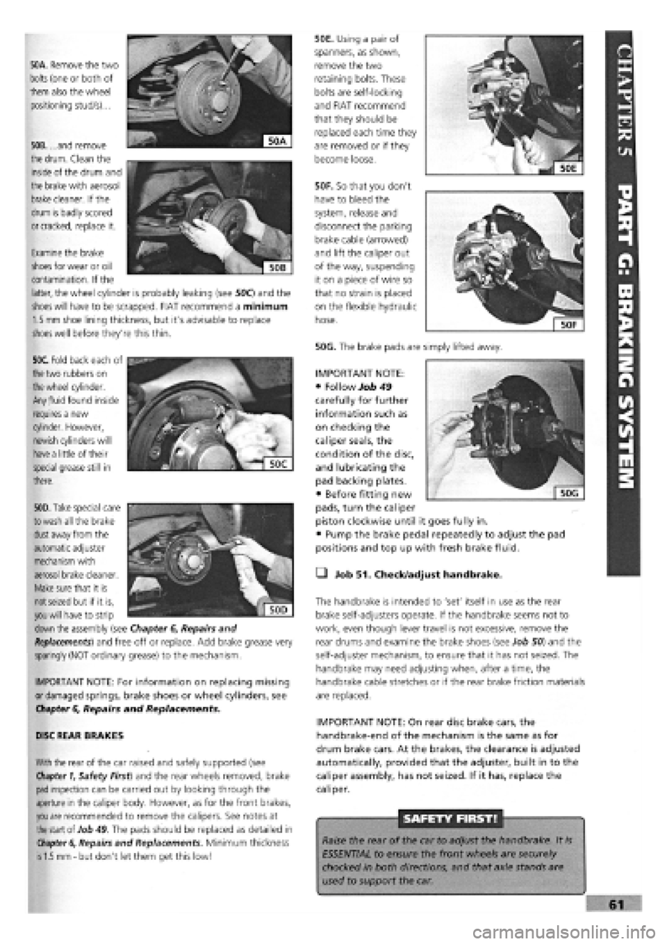
50A. Remove the two
bolts
(one or both of
them also the wheel
positioning stud/s)...
50B. ...and remove
the
drum.
Clean the
inside of the drum and
the brake with aerosol
brake
cleaner. If the
drum is badly scored
or cracked,
replace it.
50F. So that you don't
have to bleed the
system, release and
disconnect the parking
brake cable (arrowed)
and lift the caliper out
of the way, suspending
it on a piece of wire so
that no strain is placed
on the flexible hydraulic
hose.
50G. The brake pads are simply lifted away.
50E. Using a pair of
spanners, as shown,
remove the two
retaining bolts. These
bolts are self-locking
and FIAT recommend
that they should be
replaced each time they
are removed or if they
become loose.
Examine the brake
shoes
for wear or oil
contamination. If the
latter, the wheel cylinder is probably leaking (see 50C) and the
shoes will
have to be scrapped. FIAT recommend a minimum
1.5 mm
shoe lining thickness, but it's advisable to replace
shoes
well before they're this thin.
50C. Fold back each of
the
two rubbers on
the wheel
cylinder.
Any
fluid
found inside
requires a new
cylinder. However,
newish cylinders will
have a
little of their
special grease still in
there.
. """
€
Sjjj
KV,1
| 50D|
50D. Take
special care
to wash
all the brake
dust
away from the
automatic adjuster
mechanism with
aerosol brake cleaner.
Make
sure that it is
not seized
but if it is,
you will
have to strip
down
the assembly (see Chapter
6,
Repairs and
Replacements)
and free off or replace. Add brake grease very
sparingly (NOT ordinary grease) to the mechanism.
IMPORTANT NOTE: For information on replacing missing
or damaged springs, brake shoes or wheel cylinders, see
Chapter
6,
Repairs and Replacements.
DISC REAR BRAKES
With
the rear of the car raised and safely supported (see
Chapter 1,
Safety First) and the rear wheels removed, brake
pad
inspection can be carried out by looking through the
aperture in the caliper body. However, as for the front brakes,
you are
recommended to remove the calipers. See notes at
the
start of Job
49.
The pads should be replaced as detailed in
Chapter 6,
Repairs and Replacements. Minimum thickness
is 1.5 mm -
but don't let them get this low!
• Job 51. Check/adjust handbrake.
The handbrake is intended to 'set' itself in use as the rear
brake self-adjusters operate. If the handbrake seems not to
work, even though lever travel is not excessive, remove the
rear drums and examine the brake shoes (see Job 50) and the
self-adjuster mechanism, to ensure that it has not seized. The
handbrake may need adjusting when, after a time, the
handbrake cable stretches or if the rear brake friction materials
are replaced.
IMPORTANT NOTE: On rear disc brake cars, the
handbrake-end of the mechanism is the same as for
drum brake cars. At the brakes, the clearance is adjusted
automatically, provided that the adjuster, built in to the
caliper assembly, has not seized. If it has, replace the
caliper.
SAFETY FIRST!
Raise the rear of the car to adjust the handbrake. It
is
ESSENTIAL to ensure the front wheels are securely
chocked in both directions, and that axle stands are
used to support the car.
IMPORTANT NOTE:
• Follow Job 49
carefully for further
information such as
on checking the
caliper seals, the
condition of the disc,
and lubricating the
pad backing plates.
• Before fitting new
pads, turn the caliper
piston clockwise until it goes fully in.
• Pump the brake pedal repeatedly to adjust the pad
positions and top up with fresh brake fluid.
Page 58 of 171
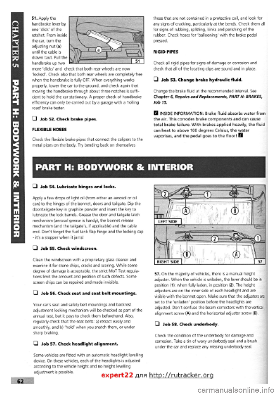
51. Apply the
handbrake lever by
one 'click' of the
ratchet. From inside
the car, turn the
adjusting nut (a)
until the cable is
drawn taut. Pull the
handbrake up two
more 'clicks' and check that both rear wheels are now
'locked'. Check also that both rear wheels are completely free
when the handbrake is fully OFF. When everything works
properly, lower the car to the ground, and check again that
moving the handbrake through about three notches is suffi-
cient to hold the car stationary. A proper check of handbrake
efficiency can only be carried out by a garage with a 'rolling
road' brake tester.
Q Job 52. Check brake pipes.
FLEXIBLE HOSES
Check the flexible brake pipes that connect the calipers to the
metal pipes on the body. Try bending back on themselves
those that are not contained in a protective coil, and look for
any signs of cracking, particularly at the bends. Check them all
for signs of rubbing, splitting, kinks and perishing of the
rubber. Check hoses for 'ballooning' with the brake pedal
pressed.
RIGID PIPES
Check all rigid pipes for signs of damage or corrosion and
check that all of the locating clips are sound and in place.
• Job 53. Change brake hydraulic fluid.
Change the brake fluid at the recommended interval. See
Chapter
6,
Repairs and Replacements, PART H: BRAKES,
Job 15.
H INSIDE INFORMATION: Brake fluid absorbs water from
the air. This corrodes brake components and can cause
total brake failure. With brakes applied heavily, the fluid
can heat to above 100 degrees Celsius, the water
vaporises, and the pedal goes to the floor! B
PART H: BODYWORK & INTERIOR
• Job 54. Lubricate hinges and locks.
Apply a few drops of light oil (from either an aerosol or oil
can) to the hinges of the bonnet, doors and tailgate. Dip the
door/tailgate key in graphite powder and insert the key to
lubricate the lock barrels. Grease the door and tailgate latch
mechanism (aerosol grease is handy), the bonnet release
mechanism (and the tailgate's, if applicable) and the cable
end. Don't forget the fuel tank flap hinge and the locking cap
- it's a stopper when it jams!
• Job 55. Check windscreen.
Clean the windscreen with a proprietary glass cleaner and
examine it for stone chips, cracks and scoring. While some
degree of damage is acceptable, the strict MoT Test regula-
tions limit the amount and position of such defects. Some
screen chips can be repaired and made invisible.
• Job 56. Check seat and seat belt mountings.
Your car's seat and safety belt mountings and backrest
adjustment locking mechanism will be checked as part of the
annual test, but it pays to check them beforehand. Also,
regularly check that the seat belts: a) retract easily and
smoothly, and b) 'hold' when you snatch them, or under
sharp braking.
Q Job 57. Check headlight alignment.
Some vehicles are fitted with an automatic headlight levelling
device. On these vehicles, each of the headlights is adjusted
according to the vehicle height and no height levelling
adjustment is possible.
57. On the majority of vehicles, there is a manual height
adjuster. When the vehicle is unladen, the lever should be in
position (1): when fully laden, in position (2). The height
adjusters are on the inner side of each headlight and are
visible with the bonnet open. Make sure that the adjusters are
set to the 'unladen' position before the headlights are
adjusted. Don't confuse the beam correctors with the vertical
alignment screw (A) and the horizontal adjuster screw (B).
• Job 58. Check underbody.
Check the condition of the underbody for damage and
corrosion. Take a tin of waxy underbody seal and a brush
under the car and replace any missing underbody seal.
expert22 fl/ia http://rutracker.org
RIGHT SIDE
Page 59 of 171

—1 Job 59. Check spare tyre.
This
job should ideally be carried out every month or two
-
you
never know when you're going to need that spare! But if you
haven't remembered, do it at the time shown on the Service
Interval Chart at the latest.
Q INSIDE INFORMATION: Put in the maximum recom-
mended pressure for heavy-duty use
-
it's always easier
to let some air out if necessary, than to put some in. Lift
the spare out check the 'hidden' lower side wall
for cracking. See Job 6. E9
PART I: ROAD TEST
Q Job 62. Road test and specialist check
-
after
every service.
Before you can claim to have 'finished' working on your car,
you must check it, test it, and, if necessary, have a qualified
mechanic check it over for you.
If you
are not a qualified mechanic, we strongly recommend
having someone who is a properly qualified mechanic
-
your
FIAT dealership perhaps
-
inspect all of the car's safety-related
items
after they have been worked on at home and before
using
the car on the road.
You'll have to remove the toolkit and the wheel to get at the
valve
-
under the boot floor on most models but to one side of
the rear compartment on Estate versions.
• Job 60. Change pollen filter.
When fitted to the fresh air intake, replace it at the scheduled
mileage interval.
• Job 61. Replace airbag gas generator.
Have your FIAT dealer replace the airbag gas generator 10
years after the car was built
-
see the label inside the car's
glove compartment door.
• Before setting out, check that the lights, indicators and in-
car controls, as well as seat belts and seat adjustments, all
work correctly.
• Run the car for several minutes before setting out then turn
off, check fluid levels and check underneath for leaks.
• Check that the steering moves freely in both directions and
that the car does not 'pull' one way or the other when driving
in a straight line
-
but do bear in mind the effect of the
camber on the road.
• Make sure that the brakes work effectively, smoothly and
without the need for 'pumping'. There should be no juddering
or squealing.
• Check that the car does not 'pull' from one side to the
other when you brake firmly from around 40 mph. (Don't
cause a skid and don't try this if there is any following traffic.)
"V,
WURTH PRODUCTS FROM FIAT
A.
Wurth produce a huge range of very high quality, FIAT-
approved products, from zinc-rich aerosol paints,
rust-proofing products and the safety-related items shown
here...
B. ...to electrical connectors and tools and that wonderful
'shrink-fit' wire insulation tubing
-
slide it on, heat it up, and it
'shrinks' into place and can't come undone again. See your
FIAT dealer or other specialist supplier for the vast range of
top-quality Wurth products.
Page 60 of 171

Please read the whole of CHAPTER
1,
SAFETY FIRST before carrying out any work on your car.
CHAPTER 6
REPAIRS AND REPLACEMENTS
This chapter shows you how
to remove and overhaul all
the major 'wearing' parts of
the car. We deliberately don't
show how to rebuild major
components, such as the
gearbox, or differential. You
are much better off, in terms
of time, cost and the
provision of a guarantee, to
buy a replacement unit.
The same applies to major
electrical components, such
as alternator and starter
motor. If, as we recommend,
you stick to 'original' FIAT
replacement parts, you will
maintain the original quality
of your car.
PART A: ENGINE
PART B: TRANSMISSION AND CLUTCH
PART C: COOLING SYSTEM
PART D: IGNITION
PART E: ELECTRICAL AND INSTRUMENTS
:er Contents
PARTf: FUEL AND EXHAUST
PART G: STEERING AND SUSPENSION
PART H: BRAKES
PART I: BODY AND INTERIOR
110
Page No.
116
127
134
143
Illustration and Section Numbers
• In this chapter, each area of the car is dealt with in a
different PART of the chapter, such as, PART A: ENGINE.
• Each job in each PART has a separate identifying number.
For example Job 2. Cylinder head removal.
• Every Job is broken down into easy-to-follow Steps,
numbered from 1-on.
• Illustrations are numbered so that you can see at a glance
where they belong!
• The illustration Job
1-3
(in PART A) for example, relates to
the text in Job 1, Step 3.
SAFETY FIRST!
• Before carrying out any of the work in this chapter,
be sure to read and understand Chapter 1, Safety
First!
• Be sure to read any safety notes supplied with any
of
the materials for equipment you purchase in
connection with the work described in this chapter.
• If you are not sure about your competence or
skills in
carrying out any of the work described in this chapter,
have the work carried out by your FIAT dealership.
FACT FILE: TIPO and TEMPRA ENGINE TYPES
PETROL ENGINES: The engines covered by
this manual are by far the most commonly
found in the UK. There may be the odd few with
different capacities or specifications which have been imported
from other countries but even they are usually similar. Here we
are concerned with one type of OHC (overhead camshaft)
PETROL engine, in 1372cc (1400) and 1581cc (1600) capacities.
They are best identified by the fact that the 1400 has its
distributor mounted on the side of the cylinder block and the
1600 has a distributor which is mounted on the end of the
camshaft, flywheel end.
DIESEL ENGINES: The Diesel engines covered here are the
1697cc (1700), the 1929cc (1900) and the 1929cc (1900) turbo.
It would take a trained eye to spot any differences between the
normally aspirated engines, but the turbo mounted on the
exhaust manifold together with its associated extra 'plumbing'
easily identifies the most powerful version.
Page 61 of 171

PART A: ENGINE
PART A: Contents
Job 1. Petrol engine. Timing belt
-
replacement and Job 12. Petrol engine. Mountings
-
replacement.
adjustment. Job 13. Diesel engine. Timing belt
-
replacement and
Job 2. Petrol engine. Cylinder head
-
removal. adjustment. •
Job 3. Petrol engine. Cylinder head and camshaft housing -Job 14. Diesel engine. Cylinder head
-
removal.
refitting. Job 15. Diesel engine. Cylinder head
-
refitting.
Job
4.
Petrol engine. Cylinder head
-
dismantling and Job 16. Diesel engine. Cylinder head
-
overhaul.
overhauling. Job 17. Diesel engine. Valve clearances
-
adjustment.
Job 5. Petrol engine
-
dismantling. Job 18. Diesel engine
-
removal.
Job
6.
Petrol engine
-
checking and reassembly. Job 19. Diesel engine
-
refitting.
Job
7.
Petrol engine. Valve clearances
-
adjustment. Job 20. Diesel engine. Mountings
-
replacement.
Job 8. Petrol engine/transmission
-
removal. Job 21. Diesel engine/transmission (removed from car)
-
Job
9.
Petrol engine/transmission
-
refitting. separation.
Job 10. Petrol engine/transmission (removed from car)
-
Job 22. Diesel engine/transmission (removed from car)
-
separation. reconnection.
Job 11. Petrol engine/transmission (removed from car)
-
Job 23. Diesel engine
-
dismantling.
reconnection. Job 24. Diesel engine
-
reassembly.
Job 1. Petrol engine. Timing belt
- replacement and adjustment.
Mi*^^ Zc+sc, / • The crankshaft pulley nut
n^^ will be difficult to turn.
• If the engine is in the car,
engage a gear (or 'Park' in the case of an automatic)
and have an assistant hold the footbrake down very
firmly. This will stop the engine from turning.
• Alternatively, with the starter motor removed, you
can have a helper prevent the flywheel ring gear from
turning with a large screwdriver.
• Step 4: Before removing the belt, put the pulley nut back
onto the crankshaft, take the car out of gear (if the engine is
still in the car) and remove the spark plugs. You can now turn
the engine in a clockwise direction using the refitted crank
pulley nut
-
without the pulley, of course!
• Step 5A: With
the timing belt still in
place, turn the engine
so that the timing
mark on the camshaft
sprocket lines up with
the one on the front
cover. On some
engines, the front
cover looks like this...
• Step 5B:
...while on the
majority, it looks
like this. The top
part of the cover
backplate slides
out so that the
plastic pip is level
with the camshaft
sprocket. Turn
the sprocket so that the timing mark on the sprocket lines up
with this pip.
IMPORTANT NOTE: It is false economy to refit a used
timing belt. If the belt breaks, it will cause complete
engine failure so always fit a new one.
• Step 1:
Disconnect the battery
and
remove the
alternator drivebelt as
described in PART C:
COOLING
SYSTEM
0 Step 2: Take off
the timing
belt cover.
This is held
by a total
of
four bolts (arrowed).
• Step 3: Take off
the
crankshaft pulley
nut and
remove the
pulley.
Page 64 of 171

SAFETY FIRST! • Step 7:
Disconnect the
electrical leads from
the following: the
inlet manifold
• Step 2: Disconnect both battery leads, negative
terminal first.
Q Step 3: Drain the cooling system and depressurise the
fuel system, if yours is a fuel injection engine
-
see PART
F:
FUEL AND EXHAUST
• Step 6B:
INJECTION
ENGINES.
Disconnect the
engine end of the
accelerator cable (a),
the idle speed check
actuator (b) and the
injector supply (c).
• Step 8: Detach
the exhaust
downpipe from the
manifold.
• Step 9: Remove
the dipstick
(arrowed) and the
cylinder head
coolant temperature
sensor (arrowed).
• Step 10: Also remove all the HT leads (along with the
distributor cap). Place them to one side.
• Step 11: Undo the brake servo hose from the manifold.
Q Step 4: Remove the air cleaner by releasing the spring
clips (a) at the front of the unit and the screw on the top face
(b) and disconnect the hoses
recovery pipe clips from beneath the rear of the housing, once
it is free to lift up.
Q Step 5: Disconnect the crankcase vent hose from the
cylinder head and the inlet tract or the SPI injector unit, as
appropriate and blank off with a bolt of suitable size.
• Step 6A:
CARBURETTOR
ENGINES.
Disconnect the
engine end of the
accelerator cable
from its idler and
the choke cable
from its mounting.
Q Step 12: Remove the
water hoses connected to
the inlet manifold and
thermostat.
• Step 13 A:
CARBURETTOR
ENGINES. Disconnect the
fuel pipe from the carbu-
rettor and both pipes
from the fuel pump.
(Label both the pipes and
stubs so that they will be
reconnected the
right way round.)
• Step 13B:
INJECTION
ENGINES.
Disconnect the fuel
supply and return
hoses from the
injector unit housing
(a). Plug the ends.
• Step 14A: CARBURETTOR ENGINES. Disconnect the
distributor vacuum pipe and oil vapour pipes from the carbu-
rettor.
vacuum sensor
(arrowed), the
manifold coolant
temperature sensors
(arrowed) and the
throttle position
switch and any
other leads which your engine may have.