1988 FIAT TEMPRA open bonnet
[x] Cancel search: open bonnetPage 5 of 171

Please read the whole of the CHAPTER 1, SAFETY FIRST! before carrying out any work on your car.
CHAPTER 2
USING YOUR CAR
This Chapter is taken from
FIAT's own official Handbooks
on the Tipo and Tempra. It
contains important and
helpful information for the
operation of your FIAT Tipo or
Tempra.
KEYS AND LOCKS
• 1. DOORS AMD BONNET
DOOR LOCKS
Most FIAT Tipos and Tempras have manual locking. You
turn the key in the lock in the normal way to lock and
unlock the door.
CHILDPROOF LOCKS
1 A.
Some models are
fitted with childproof
locks. You will find them
in the ends of the rear
doors, when open.
• Place your ignition key in
notch A, in the end of the
door, when open.
• Turn to the right to lock the childproof rear door
locks; turn to the left to unlock.
REMOTE LOCKING/UNLOCKING
1B. A
directional
signal is
emitted
when you
press button
C on your
remote unit
(early
models) or
on your
ignition key
(later
models).
IMPORTANT NOTE: The presence of dirt, snow or
ice on the side windows may prevent operation.
We recommend that you
read this chapter
carefully, so that you will
become familiar with your
vehicle's controls and
instruments.
Receiving Unit In Car: The receiving unit can store up
to 6 codes. Tag D, supplied with every receiver, has a
code number stamped on it. Keep this tag in a safe
place
-
replacements are very expensive.
To Store the Code of Your Transmitter:
• Press and hold down button A with a ball-point pen.
The red LED B illuminates, indicating that the receiving
unit is ready to store the code.
• Hold down button C on your remote unit/ignition key.
• The LED at B turns off, indicating that the receiver has
stored the code.
• Release Button A. Red LED B flashes for about 8
seconds to confirm that the code has been stored.
If you press button A again within 8 seconds, the red
LED B illuminates indicating that the receiving unit is
ready to store another code. Repeat the procedure.
If you lose a remote unit there are two ways to store a
new code:
Using a Remote Unit With Code Already Stored:
• Press and hold down button A. After about 2 seconds
red LED B flashes once.
• Press button C on the remote whose code has been
stored. Red LED B illuminates.
• Release button A. Red LED B flashes for 8 seconds
indicating new code has been stored.
Manual Operation: Have tag D ready. The four
numbers stamped on the tag will be used in this
procedure:
• Press Button A twice. Red LED B flashes 3 times and
then turns off for about 2 seconds.
• When LED B lights up again, press button A the
number of times indicated by the first code number on
tag D (if 0 do not press the button). Two seconds after
pressing button A , LED B will turn off for 2 seconds.
Page 11 of 171
SAFETY FIRST!
If an air bag has been fitted to your vehicle:
• DO NOT apply stickers or any other objects to
the steering wheel as this may restrict the
operation of the air bag.
• NEVER travel with anything on your lap or in
front of your chest
• NEVER drive with a cigarette, pipe, pen or any
other object in your mouth.
• 12. INTERIOR LIGHTS
COURTESY LIGHT
On most models the courtesy light is positioned in the
centre of the roof.
• With the light switch in the central position the light
turns on when either of the front doors is opened.
• When the switch is in the right position the light
remains on.
• With the switch in the left position the light is
switched off.
• 13. SUNROOF OPERATION
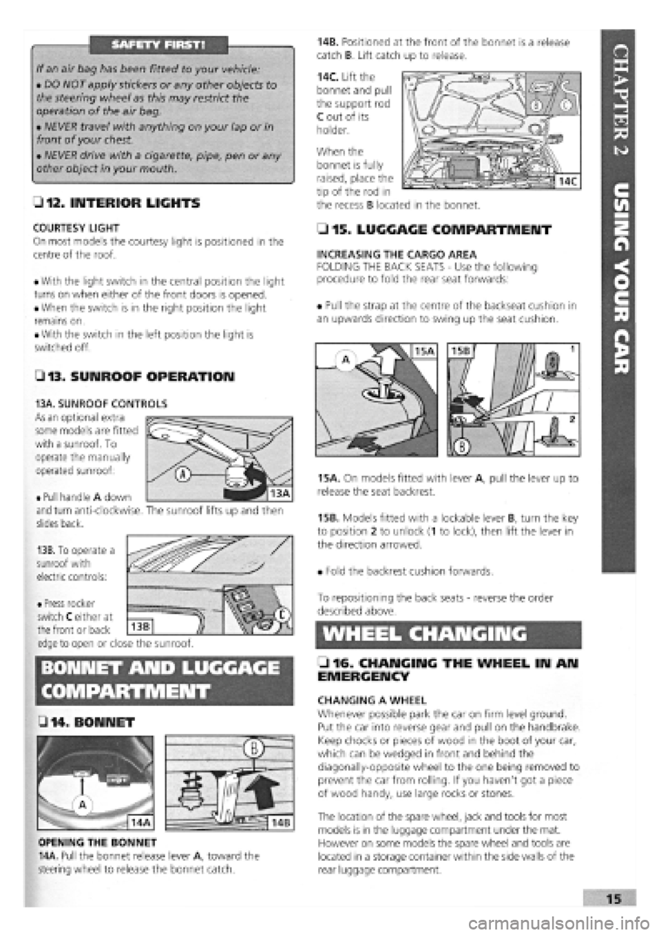
14B. Positioned at the front of the bonnet is a release
catch B. Lift catch up to release.
14C. Lift the
bonnet and pull
the support rod
C out of its
holder.
When the
• 15. LUGGAGE COMPARTMENT
INCREASING THE CARGO AREA
FOLDING THE BACK SEATS
-
Use the following
procedure to fold the rear seat forwards:
• Pull the strap at the centre of the backseat cushion in
an upwards direction to swing up the seat cushion.
15A. On models fitted with lever A, pull the lever up to
release the seat backrest.
15B. Models fitted with a lockable lever B, turn the key
to position 2 to unlock (1 to lock), then lift the lever in
the direction arrowed.
• Fold the backrest cushion forwards.
BONNET AND LUGGAGE
L 2 . fj§
• 14 .BONNET
OPENING THE BONNET
14A. Pull the bonnet release lever A, toward the
steering wheel to release the bonnet catch.
To repositioning the back seats
-
reverse the order
described above.
WHEEL CHANGING
• 16. CHANGING THE WHEEL IN AN
EMERGENCY
CHANGING A WHEEL
Whenever possible park the car on firm level ground.
Put the car into reverse gear and pull on the handbrake.
Keep chocks or pieces of wood in the boot of your car,
which can be wedged in front and behind the
diagonally-opposite wheel to the one being removed to
prevent the car from rolling. If you haven't got a piece
of wood handy, use large rocks or stones.
The location of the spare wheel, jack and tools for most
models is in the luggage compartment under the mat.
However on some models the spare wheel and tools are
located in a storage container within the side walls of the
rear luggage compartment.
bonnet is fully
raised, place the
tip of the rod in
the recess B located in the bonnet.
• Pull handle A down
and turn anti-clockwise,
slides back.
13B. To operate a
sunroof with
electric controls:
13A. SUNROOF CONTROLS
As an optional extra
some models are fitted
with a sunroof. To
operate the manually
operated sunroof:
The sunroof lifts up and then
• Press rocker
switch C either at
the front or back
edge to open or close the sunroof.
Z3
Page 58 of 171
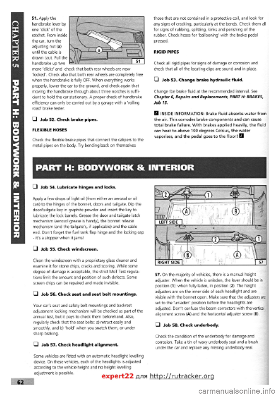
51. Apply the
handbrake lever by
one 'click' of the
ratchet. From inside
the car, turn the
adjusting nut (a)
until the cable is
drawn taut. Pull the
handbrake up two
more 'clicks' and check that both rear wheels are now
'locked'. Check also that both rear wheels are completely free
when the handbrake is fully OFF. When everything works
properly, lower the car to the ground, and check again that
moving the handbrake through about three notches is suffi-
cient to hold the car stationary. A proper check of handbrake
efficiency can only be carried out by a garage with a 'rolling
road' brake tester.
Q Job 52. Check brake pipes.
FLEXIBLE HOSES
Check the flexible brake pipes that connect the calipers to the
metal pipes on the body. Try bending back on themselves
those that are not contained in a protective coil, and look for
any signs of cracking, particularly at the bends. Check them all
for signs of rubbing, splitting, kinks and perishing of the
rubber. Check hoses for 'ballooning' with the brake pedal
pressed.
RIGID PIPES
Check all rigid pipes for signs of damage or corrosion and
check that all of the locating clips are sound and in place.
• Job 53. Change brake hydraulic fluid.
Change the brake fluid at the recommended interval. See
Chapter
6,
Repairs and Replacements, PART H: BRAKES,
Job 15.
H INSIDE INFORMATION: Brake fluid absorbs water from
the air. This corrodes brake components and can cause
total brake failure. With brakes applied heavily, the fluid
can heat to above 100 degrees Celsius, the water
vaporises, and the pedal goes to the floor! B
PART H: BODYWORK & INTERIOR
• Job 54. Lubricate hinges and locks.
Apply a few drops of light oil (from either an aerosol or oil
can) to the hinges of the bonnet, doors and tailgate. Dip the
door/tailgate key in graphite powder and insert the key to
lubricate the lock barrels. Grease the door and tailgate latch
mechanism (aerosol grease is handy), the bonnet release
mechanism (and the tailgate's, if applicable) and the cable
end. Don't forget the fuel tank flap hinge and the locking cap
- it's a stopper when it jams!
• Job 55. Check windscreen.
Clean the windscreen with a proprietary glass cleaner and
examine it for stone chips, cracks and scoring. While some
degree of damage is acceptable, the strict MoT Test regula-
tions limit the amount and position of such defects. Some
screen chips can be repaired and made invisible.
• Job 56. Check seat and seat belt mountings.
Your car's seat and safety belt mountings and backrest
adjustment locking mechanism will be checked as part of the
annual test, but it pays to check them beforehand. Also,
regularly check that the seat belts: a) retract easily and
smoothly, and b) 'hold' when you snatch them, or under
sharp braking.
Q Job 57. Check headlight alignment.
Some vehicles are fitted with an automatic headlight levelling
device. On these vehicles, each of the headlights is adjusted
according to the vehicle height and no height levelling
adjustment is possible.
57. On the majority of vehicles, there is a manual height
adjuster. When the vehicle is unladen, the lever should be in
position (1): when fully laden, in position (2). The height
adjusters are on the inner side of each headlight and are
visible with the bonnet open. Make sure that the adjusters are
set to the 'unladen' position before the headlights are
adjusted. Don't confuse the beam correctors with the vertical
alignment screw (A) and the horizontal adjuster screw (B).
• Job 58. Check underbody.
Check the condition of the underbody for damage and
corrosion. Take a tin of waxy underbody seal and a brush
under the car and replace any missing underbody seal.
expert22 fl/ia http://rutracker.org
RIGHT SIDE
Page 107 of 171
Job 6. Hatchback wiper motor -
replacement.
• Step 3: Disconnect the drive cable from the back of
speedometer.
• Step 4: From under the bonnet, uncouple the two cable
halves
from the centre connector and withdraw the
speedometer section through the bulkhead.
Q Step 5: Disconnect the lower end of the cable from the
gearbox drive and remove it.
G Step 6: Follow the reverse procedure to refit the cable,
being
careful to run the cable as straight as possible, avoiding
sharp bends.
Job 5. Windscreen wiper motor -
replacement.
Q Step 1: Disconnect the battery negative (earth) terminal.
Q Step 2: Note the position of the wiper blades on the
screen. Remove the two windscreen wiper arms and then the
grille
cover.
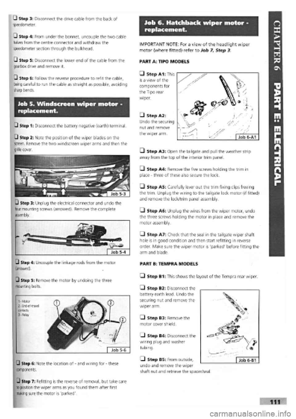
Q Step 3: Unplug the electrical connector and undo the
four mounting screws (arrowed). Remove the complete
assembly.
Q Step 4: Uncouple the linkage rods from the motor
(arrowed).
Q Step 5: Remove the motor by undoing the three
mounting bolts.
Q Step 6: Note the location of
-
and wiring for
-
these
components.
Q Step 7: Refitting is the reverse of removal, but take care
to position
the wiper arms as you found them after first
making
sure the motor is 'parked'.
IMPORTANT NOTE: For a view of the headlight wiper
motor (where fitted) refer to Job 7. Step 3.
PART A: TIPO MODELS
• Step A1: This
is a view of the
components for
the Tipo rear
wiper.
• Step A2:
Undo the securing
nut and remove
the wiper arm.
• Step A3: Open the tailgate and pull the weather strip
away from the top of the interior trim panel.
• Step A4: Remove the five screws holding the trim in
place
-
three of these also secure the lock.
Q Step A5: Carefully lever out the trim fixing clips freeing
the trim. Unplug the wiring to the tailgate lock motor (if fitted)
and remove the lock/trim panel assembly.
• Step A6: Unplug the wires from the wiper motor, undo
the three screws holding the motor in place and remove the
motor assembly.
• Step A7: Check that the seal in the tailgate wiper shaft
hole is in good condition and then start refitting in reverse
order. Make sure the wiper motor is 'parked' before fitting the
arm and blade.
PART B: TEMPRA MODELS
• Step B1: This shows the layout of the Tempra rear wiper.
Q Step B2: Disconnect the
battery earth lead. Undo the
securing nut and remove the
wiper arm.
Q Step B3: Remove the
motor cover shield.
Q Step B4: Disconnect the
wiring plug and washer
tubing.
• Step B5: From outside,
undo and remove the wiper
shaft nut and retrieve the spacer/seal.
Page 114 of 171
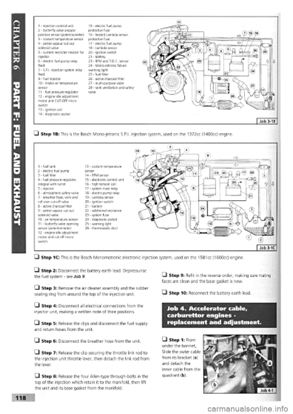
1 - injection control unit 15 - electric fuel pump 2 - butterfly valve angular protective fuse position sensor (potentiometer) 16 - heated Lambda sensor 3 - coolant temperature sensor protective fuse 4 - petrol vapour cut-out 17 - electric fuel pump solenoid valve 18 - Lambda sensor 5 - current restricter resistor for 20 - ignition switch injector 21 - battery 6 - electric fuel pump relay 23 - RPM and T.D.C. sensor feed 24 - Mono-Jetronic failure 7 - S.P.I, injection system relay warning light feed 25
-
fuel filter 9 - fuel injector 26 - active charcoal filter 10 - intake air temperature 27 - multi-purpose valve sensor 28 - tank ventilation and safety 11 - fuel pressure regulator valve 12 - engine idle adjustment motor and CUT-OFF micro switch 13 - ignition coil 14 - diagnostic socket
Q Step 1B: This is the Bosch Mono-jetronic S.P.I, injection system, used on the 1372cc (1400cc) engine.
1 - fuel tank 13 coolant temperature 2 - electric fuel pump sensor 3 - fuel filter 14 RPM sensor 4 - fuel pressure regulator, 15 electronic control unit integral with turret 16 - high tension coil 5 - injector 17 - system main relay 6 - atmospheric safety valve 18 - electric pump relay 7 - breather float, vent and 19 - Lambda sensor roll over cut-off valve 20 - ignition switch 8 - active charcoal filter 21 - battery 9 - petrol vapour cut out 22 - additional resistance solenoid valve 23 - system fuse 10 - air temperature sensor 24 - diagnostic socket 11 - butterfly valve opening 25 - warning light sensor (potentiometer) 26 - thermostatic duct 12 - engine idle adjustment motor and cut-off micro switch
Q Step 1C: This is the Bosch Monomotronic electronic injection system, used on the
1581
cc (1600cc) engine.
• Step 2: Disconnect the battery earth lead. Depressurise
the fuel system
-
see Job 9.
• Step 3: Remove the air cleaner assembly and the rubber
sealing ring from around the top of the injection unit.
Q Step 4: Disconnect all electrical connections from the
injector unit, making a written note of their positions.
Q Step 5: Release the clips and disconnect the fuel supply
and return hoses from the unit.
G Step 6: Disconnect the breather hose from the unit.
• Step 7: Release the clip securing the throttle link rod to
the injection unit throttle lever, then detach the link rod from
the lever.
Q Step 8: Release the four Allen-type through-bolts in the
top of the injection which retain it to the manifold, then lift
the unit and its base gasket from the manifold.
• Step 9: Refit in the reverse order, making sure mating
faces are clean and the base gasket is new.
• Step 10: Reconnect the battery earth lead.
Job 4. Accelerator cable,
carburettor engines -
replacement and adjustment.
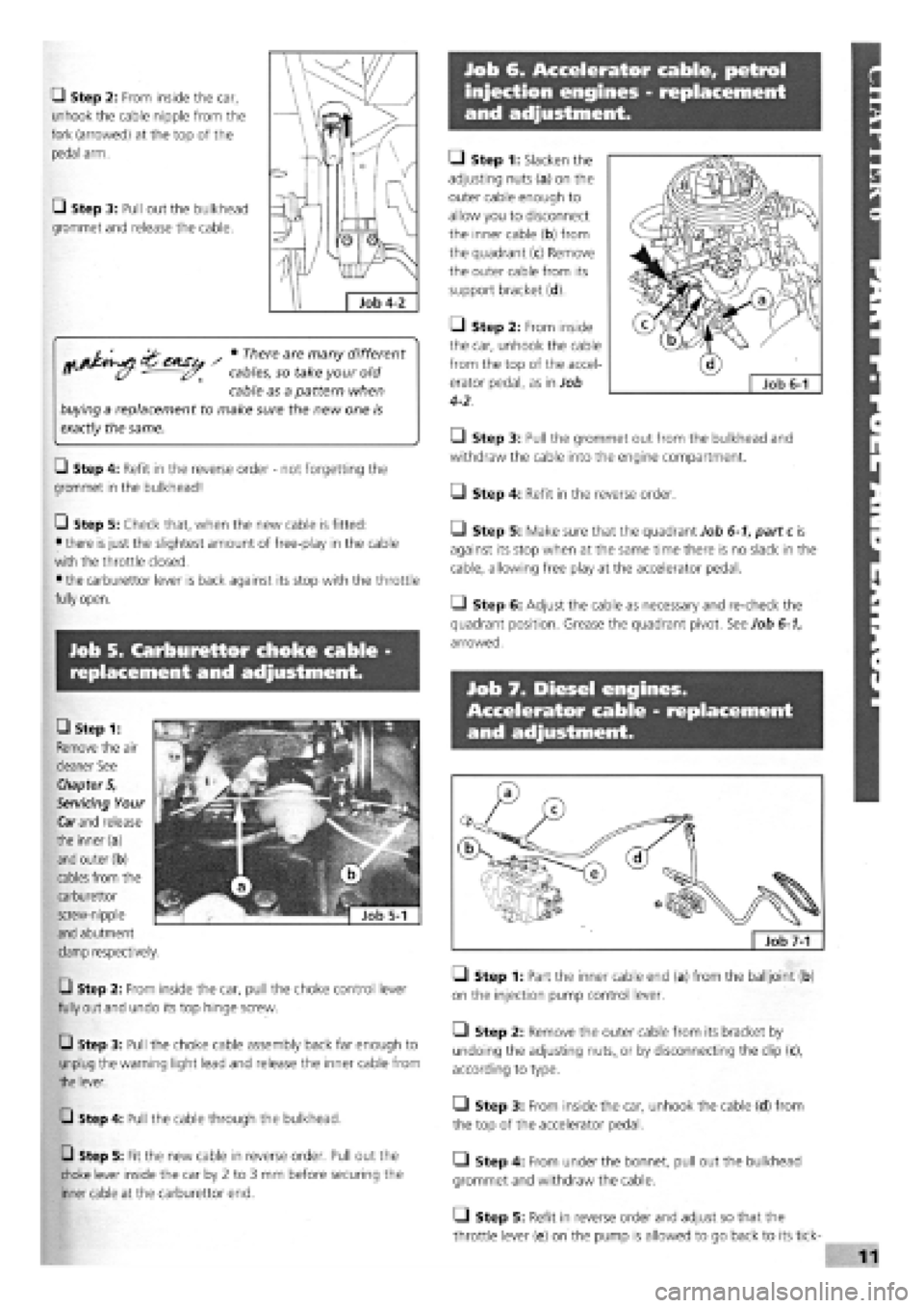
• Step 1: From
under the bonnet,
Slide the outer cable
from its bracket (a)
and detach the
inner cable from the
quadrant (b).
118
Page 115 of 171
Job 6. Accelerator cable, petrol
injection engines - replacement
and adjustment.
Q Step 2: From inside the car,
unhook the cable nipple from the
fork (arrowed) at the top of the
pedal arm.
• Step 3: Pull out the bulkhead
grommet and release the cable.
^ • There are many different
cables, so take your old
cable as a pattern when
buying a replacement to make sure the new one is
exactly
the same.
Q Step 4: Refit in the reverse order
-
not forgetting the
grommet in the bulkhead!
Q Step 5: Check that, when the new cable is fitted:
• there
is
just the slightest amount of free-play in the cable
with the throttle closed.
• the carburettor lever is back against its stop with the throttle
fully open.
• Step 1: Slacken the
adjusting nuts (a) on the
outer cable enough to
allow you to disconnect
the inner cable (b) from
the quadrant (c) Remove
the outer cable from its
support bracket (d).
Q Step 2: From inside
the car, unhook the cable
from the top of the accel-
erator pedal, as in Job
4-2.
• Step 3: Pull the grommet out from the bulkhead and
withdraw the cable into the engine compartment.
O Step 4: Refit in the reverse order.
• Step 5: Make sure that the quadrant Job 6-1, part c is
against its stop when at the same time there is no slack in the
cable, allowing free play at the accelerator pedal.
• Step 6: Adjust the cable as necessary and re-check the
quadrant position. Grease the quadrant pivot. See Job 6-1,
arrowed.
Job 7. Diesel engines.
Accelerator cable - replacement
and adjustment.
Job 5. Carburettor choke cable -
replacement and adjustment.
Q Step 2: From inside the car, pull the choke control lever
fully out and undo its top hinge screw.
Q Step 3: Pull the choke cable assembly back far enough to
unplug the warning light lead and release the inner cable from
the lever.
Q Step 4: Pull the cable through the bulkhead.
Q Step 5: Fit the new cable in reverse order. Pull out the
choke lever inside the car by 2 to 3 mm before securing the
inner cable at the carburettor end.
Q Step 1: Part the inner cable end (a) from the balljoint (b)
on the injection pump control lever.
• Step 2: Remove the outer cable from its bracket by
undoing the adjusting
nuts,,
or by disconnecting the clip (c),
according to type.
• Step 3: From inside the car, unhook the cable (d) from
the top of the accelerator pedal.
• Step 4: From under the bonnet, pull out the bulkhead
grommet and withdraw the cable.
Q Step 5: Refit in reverse order and adjust so that the
throttle lever (e) on the pump is allowed to go back to its tick-
CD Step 1:
Remove the air
cleaner See
Chapter 5,
Servicing Your
Car
and
release
the inner(a)
and outer (b)
cables from the
carburettor
screw-nipple
and abutment
clamp respectively.
Page 139 of 171

PART I: BODY AMD INTERIOR
PART 1: Contents
Job 1. Bonnet
-
removal and refitting. Job 8. Tempra boot lid locking mechanism
-
removal and
Job 2. Bonnet locking mechanism
-
replacement and refitting.
adjustment. Job 9. Front bumper and grille
-
removal and refitting.
Job 3. Radiator grille
-
removal and refitting. Job 10. Rear bumper
-
removal and refitting.
Job 4. Tipo/Tempra tailgate
-
removal and refitting. Job 11. Door trim panel
-
removal and refitting.
Job 5. Tipo tailgate locking mechanism
-
removal and Job 12. Door component
-
removal and replacement
refitting. Job 13. Door removal, replacement and adjustment.
Job 6. Tempra estate tailgate locking mechanism
-
removal Job 14. Door mirror
-
replacement.
and refitting. Job 15. Sun roof
-
removal and refitting.
Job 7. Tempra boot lid
-
removal and refitting. Job 16. Front seats
-
removal and refitting.
-Job 17. Rear seats
-
removal and refitting.
Job 1. Bonnet - removal and
refitting.
Job 2. Bonnet locking mechanism
- replacement and adjustment.
• Step 1: Note the bonnet hinges, support and stops.
G Step 2: Use the prop and hold the bonnet open. Outline
the hinge positions on the bonnet with masking tape for
accurate refitment.
G Step 3: Ask an assistant to support the bonnet. Undo the
two hinge fixing bolts. Carefully lift the bonnet clear.
if refitting the bonnet, put a
piece of cloth under each
rear corner to protect the bodywork.
• Step 1: This drawing shows left and right hand drive
layouts. Select which is right for your car.
• Step 2: The two screws (illustration Job 2-3 arrowed)
used to fix the locking pin/safety catch assembly to the bonnet
are also used for fore and aft adjustment. This is best done a
little at a time until smooth operation is achieved.
• Step 3: Height
adjustment (levelling with
the wings) is achieved by
screwing the bump stops
(inset, arrowed) up or
down. Then slacken the
G Step 5: When refitting, tighten the bolts just enough to
grip the hinges, then carefully lower the bonnet to check for
correct alignment all round
-
equal gapping.
When the alignment is satisfactory, tighten the bolts to their
correct torque, See Chapter 3, Facts and Figures
[G Step 4: To remove the lock/striker assembly, separate the
cable eyelet from the operating lever hook, see illustration Job
2-1, parts 13 and 14
1 - lock/striker assembly, front panel 2 - locking pin/safety catch, bonnet 3 - release lever. (Also fitted other side, some R/H drive cars) 4 - cable, L/H drive 5 - cable, R/H drive
and secondary cable, R/H drive 7 - screw 8
-
washer 9 - bolt 10 - bolt
11 - cable clip 12 - cable fixing screw 13 - cable eyelet 14 - operating lever hook Job 2-1
locking nut (hidden
behind the locking pin
spring) and screw the
locking pin up or down
until the bonnet will shut
when dropped from 30 cm height and then have no
movement on the lock. Don't forget to tighten the locknut.