1988 FIAT TEMPRA brake
[x] Cancel search: brakePage 26 of 171

PART C: VEHICLE RAISED OFF THE GROUND
Bodywork Structure
01
.
Any sharp edges on the external bodywork, caused by damage or corrosion will cause the vehicle to fail.
02 . Check all load bearing areas for corrosion. Open the doors and check the sills inside and out, above and below. Any corrosion in structural metalwork within 30 cm (12 in.) of seat belt mounting, steering and suspension attachment points will cause the vehicle to fail.
Wheels and Tyres
Under the Front of the
Car
You will need to support the front of the car on axle stands with the rear wheels firmly chocked in both directions.
OE . Have your helper turn the steering from lock to lock and check that the steering turns smoothly and that the brake hoses or pipes do not contact the wheel, tyre or any part of the steering or suspension.
TWI
Ob . To pass the test, the tread must be at least 1.6 mm deep throughout a continuous band comprising the central three-quarters of the width of the tread. The Tread Wear Indicators (TWI) will tell you when the limit has been reached, on most tyres.
IMPORTANT NOTE: Tyres are past their best, especially in wet conditions, well before this point is reached!
04 . Check that the front tyres match and that the rear tyres match each other
-
in terms of size and type but not necessarily make. They must be the correct size for the vehicle and the pressures must be correct.
05 . With each wheel off the ground in turn, check the inside and the outside of the tyre wall for cuts, lumps and bulges and check the wheel for damage. Note that tyres deteriorate progressively over a period of time and if they have degraded to this extent, replace them.
07 . Have your assistant hold down the brake pedal firmly. Check each brake flexible hose for bulges or leaks.
o 8. Inspect all the rigid brake pipes underneath the front of the vehicle for corrosion or leaks and also look for signs of fluid leaks at the brake calipers. Rigid fuel pipes need to be checked in the same way.
09 . At each full lock position, check the steering rack rubber gaiters for splits, leaks or loose retaining clips.
o 10. Check the track rod end dust covers to make sure they are in place.
o 11. Inspect each constant velocity joint gaiter
-
both inners and outers
-
for splits or damage. You will have to rotate each wheel to see the gaiters all the way round.
O 12. Check all of the suspension rubber mountings, including the anti-rollbar mountings (when fitted). Take a firm grip on each shock absorber in turn with both hands and try to twist the damper to check for deterioration in the top and bottom mounting bushes.
o 13. Underneath the front wheel arches, check that the shock absorbers are not corroded, that the springs have not cracked and that there are no fluid leaks down the body of the shock absorber.
o 14. While under the front end of the car, check the front of the exhaust system for security of fixing at the manifold, for corrosion and secure fixing to the mounting points.
o 15. Preferably working with a helper, grasp each front road wheel at the 12 o'clock and 6 o'clock positions and try rocking the wheel. Look for movement or wear at the suspension ball joints, suspension mountings, steering mountings and at the wheel bearing
-
look for movement between the wheel and hub. Repeat the test by grasping the road wheel at 3 o'clock and 9 o'clock and rocking once more.
o 16. Spin each wheel and check for noise or roughness in the wheel bearing and binding in either the wheel bearing or the brake.
IMPORTANT NOTE: Don't forget that on front wheel drive cars, the gearbox must be in neutral. There will be a certain amount of noise and drag from the drivetrain components.
O 17. If you suspect wear at any of the suspension points, try levering with a screwdriver to see whether or not you can confirm any movement in that area.
o 18. Vehicles fitted with other suspension types such as hydraulic suspension, torsion bar suspension etc. need to be checked in a similar way with the additional point that there must be no fluid leaks or damaged pipes on vehicles with hydraulic suspension.
Underneath the Rear
of the Car
O 19. Inspect the rear springs for security at their mounting points and for cracks, severe corrosion or damage.
o 20. Check the rear shock absorbers in the same way as the checks carried out for the fronts.
o 21. Check all rear suspension mounting points, including the rubbers to any locating rods or anti-rollbar that may be fitted.
O 22. Check all of the flexible and rigid brake pipes and the fuel pipes just as for the front of the vehicle.
30
Page 27 of 171

O 23. Have your assistant press down firmly on the brake pedal while you check the rear brake flexible hoses for bulges, splits or other deterioration.
o 24. Check the fuel tank for leaks or corrosion. Remember also to check the fuel filler cap
-
a correctly sealing filler cap is a part of the MoT test.
O 25. Examine the handbrake mechanism. Frayed or broken cables or worn mounting points, either to the bodywork or in the linkage will all be failure points.
o 26. Check each of the rear wheel
bearings as for the fronts.
o 27. Spin each rear wheel and check that neither the wheel bearings nor the brakes are binding. Pull on and let off the handbrake and check once again to make sure that the handbrake mechanism is releasing.
SAFETY FIRST!
• Only run the car out of doors.
• Beware of burning yourself on a hot exhaust system.
o 28. While you are out from under the car, but with the rear end still raised off the ground, run the engine. Hold a rag over the end of the exhaust
pipe and listen for blows or leaks in the system. You can now get back under the car and investigate further if necessary.
o 29. Check the exhaust system mountings and check for rust, corrosion or holes in the rear part of the system.
o 30. Check the rear brake back plate or calipers (as appropriate) for any signs of fluid leakage.
o 31. Check the insides and the outsides of the tyres as well as the tyre treads for damage, as for the front tyres.
PART D: EXHAUST EMISSIONS
This is an area that is impossible to
check accurately at home. However,
the following rule-of-thumb tests will
give you a good idea whether your car
is likely to fail or not.
H INSIDE INFORMATION: If you
feel that your car is likely to fail
because of the emission test, have
your MoT testing station carry out
the emission part of the test first so
that if it fails, you don't waste
money on having the rest of the
test carried out. Q
O 1. PETROL ENGINES BEFORE 1 AUGUST 1973 AND DIESEL ENGINES BEFORE 1 AUGUST 1979 only have to pass visible smoke check. Rev the engine to about 2,500 rpm (about half maximum speed) for 20 seconds and then allow it to return to idle. If too much smoke is emitted (in the opinion of the tester) the car will fail.
O 2.DIESEL ENGINES FROM 1 AUGUST 1979 The engine will have to be taken up to maximum revs several times by the tester, so make certain that your timing belt is in good condition, otherwise severe damage could be caused to your engine. If the latter happens, it will be your responsibility!
FACT FILE: VEHICLE EMISSIONS
PETROL
ENGINED VEHICLES WITHOUT
CATALYSER
Vehicles first used before 1 August 1973
• visual smoke check only.
Vehicles first used between 1 August 1973 and 31 July 1986
• 4.5% carbon monoxide and 1,200 parts per million, unburned
hydrocarbons.
Vehicles first used between 1 August 1986 and 31 July 1992
• 3.5% carbon monoxide and 1,200 parts per million, unburned
hydrocarbons.
PETROL ENGINED VEHICLES FITTED WITH
CATALYTIC
CONVERTERS
i
Vehicles first used from 1 August 1992
(K-registration on)
• All have to be tested at an MoT Testing Station specially equipped to
handle cars fitted with catalytic converters whether or not the vehicle
is fitted with a 'cat'. If
the
test, or the garage's data, shows that the
vehicle was not fitted with a 'cat' by the manufacturer, the owner is
permitted to take the vehicle to
a
Testing Station not equipped for
catalysed cars, if he/she prefers to do so (up to 1998-only). Required
maxima are
-
3.5% carbon monoxide and 1,200 parts per million,
unburned hydrocarbons. The simple emissions test (as above) will be
supplemented by a further check to make sure that the catalyst is
maintained in
good
and efficient working order.
• The tester also has to check that the engine oil is up to a specified
temperature before carrying out the test. (This is because 'cats' don't
work properly at lower temperatures
-
ensure your engine is fully
warm!)
DIESEL ENGINES'EMISSIONS
STANDARDS
• The Tester will have to rev your engine hard,
several times. If it is not in good condition, he is
entitled to refuse to test it. This is the full range of
tests, even though all may not apply to your car.
Vehicles first used before 1 August, 1979
• Engine run at normal running temperature; engine speed taken to
around 2,500 rpm (or half
governed
max. speed, if lower) and held for
20 seconds. FAILURE, if engine emits dense blue or black smoke for
next 5 seconds, at tick-over. (NOTE: Testers are allowed to be more
lenient with pre-1960 vehicles.)
Vehicles first used on or after 1 August, 1979
• After checking engine condition, and with the engine at normal
running temperature, the engine will be run up to full revs between
three and six times to see whether your engine passes the prescribed
smoke density test. (For what it's worth
-
2.5k for non-turbo cars; 3.0k
for turbo diesels. An opacity meter probe will be placed in your car's
exhaust pipe and this is not something you can replicate at home.)
Irrespective of the meter readings, the car will fail if
smoke
or vapour
obscures the view of other road users.
• IMPORTANT NOTE: The diesel engine test puts a lot of stress on the
engine. It is IMPERATIVE that your car's engine is properly serviced,
and the cam belt changed on schedule, before you take it in for the
MoT test. The tester is entitled to refuse to test the car if
he
feels that
the engine is not in serviceable condition and there are a number of
pre-Test checks he may carry out.
Page 29 of 171

Thanks
are due to the excellent, knowledgeable and helpful staff at FIAT main dealers, Ryauto of Amblecote, in the West
Midlands for supplying vehicles and for their assistance with this chapter. In particular, thanks are due to the efficient Maurice
Hough, Service Manager, the experienced Foreman, Tony Morris, and young demon mechanic, Matthew Worsfold.
Some of the suggested inspection/replacement intervals may not correspond to those shown in the original handbook. The suggested
schedule, based on FIAT'S recommendations, takes into account the age of the vehicle and the annual MoT test in the UK.
In practice, because of the split between (mainly) 12 month/9,000 mile and 18 month/13,500 mile intervals, you will need to
service your Tipo or Tempra at most, if not every, 6 month interval.
IMPORTANT NOTE: Each service should be carried out at EITHER the recommended mileage OR the recommended time
interval, whichever comes first.
SERVICE INTERVAL CHART
SERVICE INTERVALS: KEY
A
-
Every week, or before every long journey. F
-
Every 3 years or 27,000 miles.
B
-
Every 6 months, or 4,500 miles. G
-
Every 4 years or 36,000 miles.
C - Every 12 months, or 9,000 miles. H
-
Every 6 years or 54,000 miles.
I
-
Every 63,000 miles. D - Every 18 months , or 13,500 miles.
H
-
Every 6 years or 54,000 miles.
I
-
Every 63,000 miles.
E
-
Every 2 years or 18,000 miles J
-
Every 72,000 miles.
PART A: REGULAR CHECKS
SERVICE INTERVALS
Job 1. Engine oil
-
check level A
Job 2. Cooling system
-
check level A
Job 3. Brake/clutch fluid
-
check level A
Job 4. Battery
-
check electrolyte level A
Job 5. Screen washer fluid
-
check level A
Job 6. Tyres
-
check pressures and
condition (road wheels) A
Job 7. Check lights/change bulbs A
PART B: THE ENGINE AND
COOLING SYSTEM
Job 8
-
Petrol. Change engine oil and filter C
Job 8
-
Diesel. Change engine oil and filter B
Job 9. Check crankcase ventilation H
Job 10. Check/adjust valve clearances D
Job 11. Check camshaft timing belt F
Job 12. Change camshaft timing belt I
Job 13. Check cooling system C
Job 14. Change engine coolant E
PART C: TRANSMISSION
Job 15. Check manual gearbox oil level C
Job 16. Change manual gearbox oil J
Job 17. Check auto, transmission fluid level C
Job 18. Change auto, transmission
fluid and filter F
Job 19. Check driveshaft gaiters C
Job 20. Check/adjust clutch C
Job 21. Check auto, transmission selector
cable E
PART D: IGNITION AND ELECTRICS
SERVICE INTERVALS
Job 22. Check/clean/gap spark plugs B
Job 23. Change spark plugs D
Job 24. Check/clean HT leads and
distributor cap C
Job 25. Check ignition timing C
Job 26. Check/adjust drive belt/s D
Job 27. Check electric fan operation C
Job 28. Run diagnostic ignition/injection test D
PART E: FUEL AND EXHAUST
Job 29. Check fuel pipes for leaks C
Job 30. Change petrol air filter D
Job 31. Change diesel air filter C
Job 32. Change petrol fuel filter F
Job 33. Drain diesel fuel filter B
Job 34. Change diesel fuel filter C
Job 35. Check/adjust petrol engine idle
and emissions C
Job 36. Check emission/evaporative/EGR systems F
Job 37. Check Lambda sensor F
Job 38. Check/adjust diesel idle speed C
Job 39. Check/adjust diesel injection timing E
Job 40. Check inlet and exhaust manifold fixings D
Job 41. Check exhaust system C
PART F: STEERING AND
SUSPENSION
Job 42. Check front wheel bearings C
Job 43. Check front suspension C
Job 44. Check steering column, joints and rack C
Job 45. Check power steering fluid C
Job 46. Check rear wheel bearings C
Job 47. Check rear suspension C
Job 48. Check wheel bolts for tightness C
Page 30 of 171

PART G: BRAKING SYSTEM
Job 49. Check front brakes
Job 50. Check rear brakes
Job 51. Check/adjust handbrake
Job 52. Check brake pipes
Job 53. Change brake hydraulic fluid
SERVICE INTERVALS
C
C
C
C
E
Job 56. Check seat and seat belt mountings C
Job 57. Check headlight alignment C
Job 58. Check underbody C
Job 59. Check spare tyre B
Job 60. Change pollen filter C
Job 61. Replace airbag gas generator 10 years
PART I: ROAD TEST
PART H: BODYWORK & INTERIOR
Job 54. Lubricate hinges and locks
Job 55. Check windscreen
Job 62. Road test and specialist check. AFTER EVERY
SERVICE
ENGINE BAY LAYOUTS
These are the engine bay layouts common to almost all Tipo/Tempras. Note that there is no carburettor fitted to fuel-injected
vehicles.
1 - PETROL ENGINES 2 - DIESEL ENGINES
1
-
oil filler cap 7
-
distributor (ignition) 12 - oil filter location
2
-
engine oil dipstick 8
-
coil (ignition) 13
-
fuel pump (mechanical)
3
-
coolant filler cap 9
-
electronic control unit (ECU), 14
-
diesel injection pump
4 - brake fluid reservoir Digiplex 2 15
-
alternator location (behind engine)
5 - battery 10
-
air filter housing
6
-
screenwash reservoir cap 11
-
fuel filter
PART A: REGULAR CHECKS
1B. ...and the diesel's
dipstick is in a similar
spot, located at the
front edge of the
timing cover, behind
the right-hand
headlight.
Q INSIDE INFORMATION: The
difference between MIN and MAX
marks is approximately one litre of
oil. Q
We recommend that these Jobs are carried out on a weekly
basis, as well as before every long journey. They consist of
checks essential for your safety and for your car's reliability.
• Job 1. Engine oil
-
check level.
Check the engine oil level with the car on level ground. If the
engine has been running, leave it turned off for several
minutes to let the oil drain into the sump.
1A. All petrol engines
have the dipstick at
the front of the block,
towards the timing
belt end...
1C. Lift the dipstick out,
wipe it dry and re-insert it. The oil
level is correct when between the
MAX and MIN marks.
Page 31 of 171
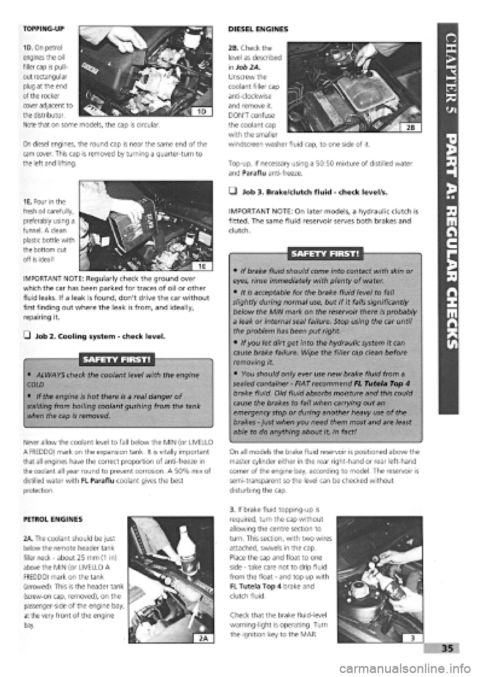
TOPPING-UP
1D. On petrol
engines the oil
filler cap is pull-
out rectangular
plug at the end
of the rocker
On diesel engines, the round cap is near the same end of the
cam cover. This cap is removed by turning a quarter-turn to
the left and lifting.
DIESEL ENGINES
Top-up, if necessary using a 50:50 mixture of distilled water
and Paraflu anti-freeze.
cover adjacent to
the distributor.
Note that on some models, the cap is circular.
1E. Pour in the
fresh oil carefully,
preferably using a
funnel. A clean
plastic bottle with
the bottom cut
off is ideal!
IMPORTANT NOTE: Regularly check the ground over
which the car has been parked for traces of oil or other
fluid leaks. If a leak is found, don't drive the car without
first finding out where the leak is from, and ideally,
repairing it.
G Job 2. Cooling system
-
check level.
SAFETY FIRST!
• ALWAYS check the coolant level with the engine
COLD
• If the engine is hot there is a real danger of
scalding
from boiling coolant gushing from the tank
when the cap is removed.
Never allow the coolant level to fall below the MIN (or UVELLO
A FREDDO) mark on the expansion tank. It is vitally important
that all engines have the correct proportion of anti-freeze in
the coolant all year round to prevent corrosion. A 50% mix of
distilled water with FL Paraflu coolant gives the best
protection.
• Job 3. Brake/dutch fluid
-
check level/s.
IMPORTANT NOTE: On later models, a hydraulic clutch is
fitted. The same fluid reservoir serves both brakes and
clutch.
SAFETY FIRST!
• If brake fluid should come into contact with skin or
eyes, rinse immediately with plenty of water.
• It is acceptable for the brake fluid level to fall
slightly during normal use, but if it falls significantly
below the MIN mark on the reservoir there is probably
a leak or internal seal failure. Stop using the car until
the problem has been put right.
• If you let dirt get into the hydraulic system it can
cause brake failure. Wipe the filler cap clean before
removing it.
• You should only ever use new brake fluid from a
sealed container
-
FIAT recommend FL Tutela Top 4
brake fluid. Old fluid absorbs moisture and this could
cause the brakes to fail when carrying out an
emergency stop or during another heavy use of the
brakes
-
just when you need them most and are least
able to do anything about it, in fact!
On all models the brake fluid reservoir is positioned above the
master cylinder either in the rear right-hand or rear left-hand
corner of the engine bay, according to model. The reservoir is
semi-transparent so the level can be checked without
disturbing the cap.
PETROL ENGINES
2A. The coolant should be just
below the remote header tank
filler neck
-
about 25 mm
(1
in)
above the MIN (or UVELLO A
FREDDO) mark on the tank
(arrowed). This is the header tank
(screw-on cap, removed), on the
passenger-side of the engine bay,
at
the very front of the engine
bay.
3. If brake fluid topping-up is
required, turn the cap without
allowing the centre section to
turn. This section, with two wires
attached, swivels in the cap.
Place the cap and float to one
side
-
take care not to drip fluid
from the float
-
and top up with
FL Tutela Top 4 brake and
clutch fluid.
Check that the brake fluid-level
warning-light is operating. Turn
the ignition key to the MAR
I
i 3
»35
2B. Check the
level as described
in
Job 2A.
Unscrew the
coolant filler cap
anti-clockwise
and remove it.
DON'T confuse
the coolant cap
with the smaller
windscreen washer fluid cap, to one side of it.
Page 42 of 171
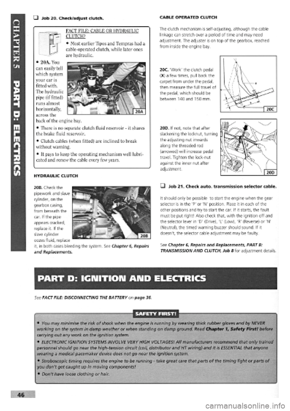
• Job 20. Check/adjust clutch. CABLE OPERATED CLUTCH
The clutch mechanism is self-adjusting, although the cable
linkage can stretch over a period of time and may need
adjustment. The adjuster is on top of the gearbox, reached
from inside the engine bay.
20C. 'Work' the clutch pedal
(X) a few times, pull back the
carpet from under the pedal,
then measure the full travel of
the pedal, which should be
between 140 and 150 mm.
/
\
/ \
/ u / Xl
1 ' ' / . V y 2
Jdi V 1 \
X. 1 —
20C
HYDRAULIC CLUTCH
20B. Check the
pipework and slave
cylinder, on the
gearbox casing,
from beneath the
20D. If not, note that after
slackening the locknut, turning
the adjusting nut inwards
along the threaded rod
(arrowed) will increase pedal
travel. Tighten the lock-nut
against the inner nut after
adjustment.
• Job 21. Check auto, transmission selector cable.
It should only be possible to start the engine when the gear
selector is in the 'P' or 'N' position. Place it in each of the
other positions and try to start the car. If it starts, the fault
must be put right! Also check that, with the ignition off and
the selector lever in 'D' (Drive), 'L' (Low), 'R' (Reverse) or 'N'
(Neutral), the timed warning buzzer should sound. If it
doesn't, the selector cable adjustment may be faulty.
See Chapter
6,
Repairs and Replacements, PART B:
TRANSMISSION AND CLUTCH, Job 8 for adjustment details.
PART D: IGNITION AND ELECTRICS
See FACT FILE: DISCONNECTING THE BATTERY on page 36
SAFETY FIRST!
• You may minimise the risk of shock when the engine is running by wearing thick rubber gloves and by NEVER
working on the system in damp weather or when standing on damp ground. Read Chapter 1, Safety First! before
carrying out any work on the ignition system.
• ELECTRONIC IGNITION SYSTEMS INVOLVE VERY HIGH VOLTAGES! All manufacturers recommend that only trained
personnel should go near the high-tension circuit (coil, distributor and HT wiring) and it is ESSENTIAL that anyone
wearing a medical pacemaker device does not go near the ignition system.
• Stroboscopic timing requires the engine to be running
-
take great care that parts of the timing light or parts of
you don't get caught up in moving components!
• Don't have loose clothing or hair.
46
FACT FILE: CABLE OR HYDRAULIC
CLUTCH?
• Most earlier Tipos and Tempras had a
cable-operated clutch, while later ones
are hydraulic.
• 2 OA. You
can easily tell
which system
your car is
fitted with.
The hydraulic
pipe (if fitted)
runs almost
horizontally,
across the
back of the engine bay.
• There is no separate clutch fluid reservoir
-
it shares
the brake fluid reservoir.
• Clutch cables (when fitted) are inclined to break
without warning.
• It pays to keep the operating mechanism well lubri-
cated and renew the cable every few years.
car. If the pipe
appears cracked,
replace it. If the
slave cylinder
oozes fluid, replace
it, in both cases bleeding the system. See Chapter
6,
Repairs
and Replacements.
Page 53 of 171
PART F: STEERING AMD SUSPENSION
G Job 42. Check front wheel bearings.
In
order to check for wear:
• raise the front of the car on axle stands (see Chapter 1,
Safety First!)
• place the gearbox in neutral
• pull the handbrake securely on and chock the rear wheels
Try
spinning each wheel (as far as possible with a front-drive
car), feeling for rough rotation. Rock the wheel about its
centre, feeling for excess bearing play.
D INSIDE INFORMATION: If a wheel bearing is worn, you
will normally hear a noise on the outer, loaded bearing
when cornering. D
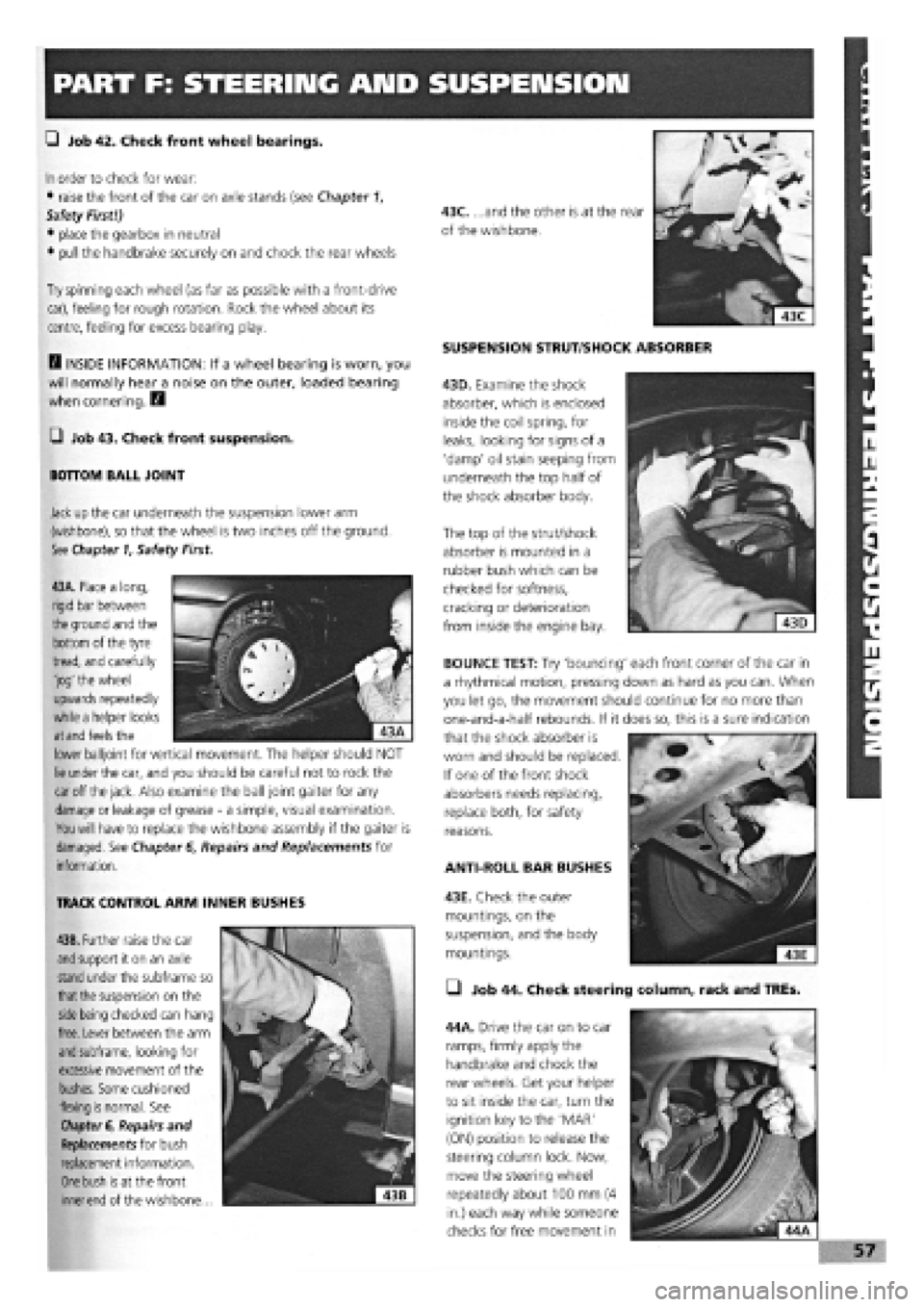
G Job 43. Check front suspension.
BOTTOM BALL JOINT
Jack
up
the car underneath the suspension lower arm
(wishbone), so that the wheel is two inches off the ground.
See Chapter
1,
Safety First.
SUSPENSION STRUT/SHOCK ABSORBER
43D. Examine the shock
absorber, which is enclosed
inside the coil spring, for
leaks, looking for signs of a
'damp' oil stain seeping from
underneath the top half of
the shock absorber body.
The top of the strut/shock
absorber is mounted in a
rubber bush which can be
checked for softness,
cracking or deterioration
from inside the engine bay.
43A. Place a long,
rigid bar between
the
ground and the
bottom of the tyre
tread, and carefully
'jog' the wheel
upwards repeatedly
while a helper looks
at and
feels the
lower balljoint for vertical movement. The helper should NOT
lie
under the car, and you should be careful not to rock the
car
off
the jack.
Also examine the ball joint gaiter for any
damage
or leakage of grease
-
a simple, visual examination.
You will
have to replace the wishbone assembly if the gaiter is
damaged. See Chapter
6,
Repairs and Replacements for
information.
TRACK CONTROL ARM INNER BUSHES
43B. Further raise the car
and
support it on an axle
stand
under the subframe so
that the
suspension on the
side being
checked can hang
free. Lever between the arm
and
subframe, looking for
excessive movement of the
bushes. Some cushioned
flexing
is
normal. See
Chapter
6, Repairs and
Replacements for bush
replacement information.
One bush is
at the front
inner end
of the wishbone...
ANTI-ROLL BAR BUSHES
43E. Check the outer
mountings, on the
suspension, and the body
mountings.
• Job 44. Check steering column, rack and TREs.
44A. Drive the car on to car
ramps, firmly apply the
handbrake and chock the
rear wheels. Get your helper
to sit inside the car, turn the
ignition key to the 'MAR'
(ON) position to release the
steering column lock. Now,
move the steering wheel
repeatedly about 100 mm (4
in.) each way while someone
checks for free movement in
BOUNCE TEST: Try 'bouncing' each front corner of the car in
a rhythmical motion, pressing down as hard as you can. When
you let go, the movement should continue for no more than
one-and-a-half rebounds. If it does so, this is a sure indication
that the shock absorber is
worn and should be replaced.
If one of the front shock
absorbers needs replacing,
replace both, for safety
reasons.
Page 54 of 171
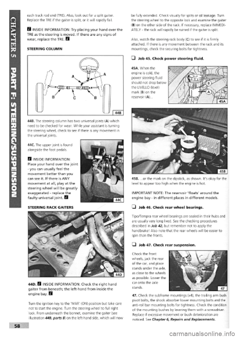
each track rod end (TRE). Also, look out for a split gaiter.
Replace the TRE if the gaiter is split, or it will rapidly fail.
E3 INSIDE INFORMATION: Try placing your hand over the
TRE as the steering is moved. If there are any signs of
wear, replace the TRE. Q
STEERING COLUMN
44B. The steering column has two universal joints (A) which
need to be checked for wear. While your assistant is turning
the steering wheel, check to see if there is any movement in
the universal joints.
44C. The upper joint is found
alongside the foot pedals.
Q INSIDE INFORMATION:
Place your hand over the joint
-
you can usually feel the
movement better than you
can see it. If there is ANY
movement at all, play at the
steering wheel will be greatly
exaggerated
-
replace the
faulty universal joint. B
STEERING RACK GAITERS
44D. B INSIDE INFORMATION: Check the right hand
gaiter from beneath; the left-hand from inside the
engine bay. Q
Turn the ignition key to the 'MAR' (ON) position but take care
not to start the engine. Turn the steering wheel to full right
lock. From underneath the bonnet, examine the gaiter (see
illustration 44B, parts B) on the left-hand side, which will now
be fully extended. Check visually for splits or oil leakage. Turn
the steering wheel to the opposite lock and examine the gaiter
(B) on the other side of the rack. If necessary, replace IMMEDI-
ATELY
-
the rack will rapidly be ruined if the gaiter is split.
Also, watch the steering rack body (C) to see if it is firmly
attached. If there is any movement between the rack and its
mountings, check the securing bolts for tightness.
• Job 45. Check power steering fluid.
45A. When the
engine is cold, the
power steering fluid
should not drop below
the LIVELLO (level)
mark (B) on the
reservoir (A)...
45B. ...or the mark on the dipstick, as shown. It's okay for the
level to appear too high when the engine is hot.
IMPORTANT NOTE: The reservoir 'floats' around the
engine bay
-
in different places in different models.
• Job 46. Check rear wheel bearings.
Tipo/Tempra rear wheel bearings are sealed in their hubs and
are usually very long lived. See the checking procedures
described in Job 42, but remember not to apply the
handbrake! Also note that the rear wheels will be easier to
spin than the fronts.
• Job 47. Check rear suspension.
Chock the front
wheels, jack the rear
of the car, and place
stands under the axle,
as close to the wheels
as possible. Lower the
car onto the axle
stands.
47. Check the subframe mountings (x4), the trailing arm bush
pivot bolts, the shock absorber lower mounting bolts and the
anti-roll bar mounting bolts for tightness. Check the condition
of the mounting bushes by levering them with a screwdriver.
Replace if excessive movement or bush deterioration are
noticed. See Chapter
6,
Repairs and Replacements.