1988 FIAT TEMPRA change time
[x] Cancel search: change timePage 98 of 171

Job 8. Automatic gear selector
control cable - replacement.
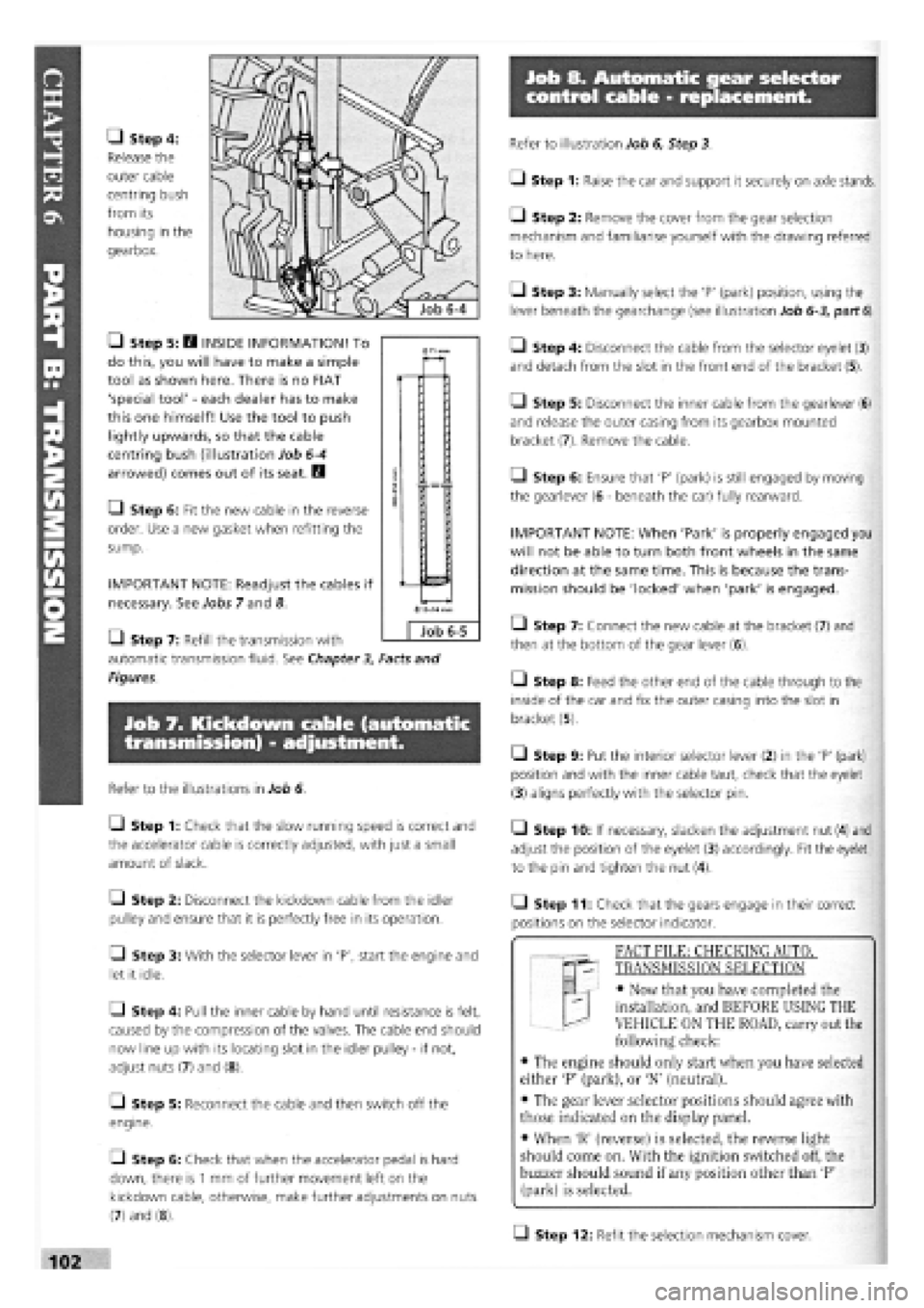
• Step 4:
Release the
outer cable
centring bush
from its
housing in the
gearbox.
• Step 5: H INSIDE INFORMATION! To
do this, you will have to make a simple
tool as shown here. There is no FIAT
'special tool'
-
each dealer has to make
this one himself! Use the tool to push
lightly upwards, so that the cable
centring bush (illustration Job
6-4
arrowed) comes out of its seat. B
• Step 6: Fit the new cable in the reverse
order. Use a new gasket when refitting the
sump.
IMPORTANT NOTE: Readjust the cables if
necessary. See Jobs 7 and 8.
Q Step 7: Refill the transmission with
automatic transmission fluid. See Chapter
3,
Facts and
Figures.
Job 7. Kickdown cable (automatic
transmission) - adjustment.
Refer to the illustrations in Job 6.
Q Step 1: Check that the slow running speed is correct and
the accelerator cable is correctly adjusted, with just a small
amount of slack.
Q Step 2: Disconnect the kickdown cable from the idler
pulley and ensure that it is perfectly free in its operation.
• Step 3: With the selector lever in 'P', start the engine and
let it idle.
Q Step 4: Pull the inner cable by hand until resistance is felt,
caused by the compression of the valves. The cable end should
now line up with its locating slot in the idler pulley
-
if not,
adjust nuts (7) and (8).
[_l Step 5: Reconnect the cable and then switch off the
engine.
• Step 6: Check that when the accelerator pedal is hard
down, there is
1
mm of further movement left on the
kickdown cable, otherwise, make further adjustments on nuts
(7) and (8).
Refer to illustration Job 6, Step 3.
• Step 1: Raise the car and support it securely on axle stands.
• Step 2: Remove the cover from the gear selection
mechanism and familiarise yourself with the drawing referred
to here.
Q Step 3: Manually select the 'P' (park) position, using the
lever beneath the gearchange (see illustration Job
6-3,
part
6).
• Step 4: Disconnect the cable from the selector eyelet (3)
and detach from the slot in the front end of the bracket (5).
Q Step 5: Disconnect the inner cable from the gearlever (6)
and release the outer casing from its gearbox mounted
bracket (7). Remove the cable.
Q Step 6: Ensure that 'P' (park) is still engaged by moving
the gearlever (6
-
beneath the car) fully rearward.
IMPORTANT NOTE: When 'Park' is properly engaged you
will not be able to turn both front wheels in the same
direction at the same time. This is because the trans-
mission should be 'locked' when 'park' is engaged.
• Step 7: Connect the new cable at the bracket (7) and
then at the bottom of the gear lever (6).
• Step 8: Feed the other end of the cable through to the
inside of the car and fix the outer casing into the slot in
bracket (5).
• Step 9: Put the interior selector lever (2) in the 'P' (park)
position and with the inner cable taut, check that the eyelet
(3) aligns perfectly with the selector pin.
• Step 10: If necessary, slacken the adjustment nut (4) and
adjust the position of the eyelet (3) accordingly. Fit the eyelet
to the pin and tighten the nut (4).
• Step 11: Check that the gears engage in their correct
positions on the selector indicator.
T "I FACT FILE: CHECKING AUTOT
qp- TRANSMISSION SELECTION
EL
-
• Now that you have completed the
installation, and BEFORE USING THE
VEHICLE ON THE ROAD, carry out the
following check:
• The engine should only start when you have selected
either 'P' (park), or 'N' (neutral).
• The gear lever selector positions should agree with
those indicated on the display panel.
• When 'R' (reverse) is selected, the reverse light
should come on. With the ignition switched off, the
buzzer should sound if any position other than 'P'
(park) is selected.
Q Step 12: Refit the selection mechanism cover.
0
Job 6-5
Page 100 of 171

Job 11. Drive-shaft inner spider
joint - replacement.
• Step 3: Replace the (split) rubber mounting and refit the
weight.
Job 13. Front hub/bearings -
replacement.
Job 11-1
a - distance - 305 mm b - spider joint c - inner gaiter d - inner bearing seal e
-
vibration damper f
-
outer gaiter
g - circlip h - outer u.j. i - hub mounting spline
• Step 1: Note the arrangement of the inner spider joint
and drive-shaft components.
Q Step 2: Remove the
drive-shaft from the car. See
Job 9.
• Step 3: Remove the
circlip and pull or press the
spider joint from the drive-
shaft.
• Step 4: Remove the inner gaiter (illustration Job
11-1,
part c) from the seal bearing (Job
11-1,
partd). Check the
bearing for wear and smooth operation.
Q Step 5: Replace it if necessary by using a standard type
puller to remove it from the shaft, driving the new one into
position with a suitable length of tubing.
Q Step 6: After obtaining a new spider joint, if necessary,
(available as a complete replacement item from your FIAT
dealership), fit the new gaiter and its retainer to the shaft,
followed by the spider joint and circlip. No lubrication is
required prior to refitting the drive-shaft.
• Step 7: E9 INSIDE INFORMATION! The turbo diesel
uses an inboard CV joint similar to the outer one except
that it has a flange for attachment to the transmission.
(See PART A: ENGINE, Job 18, Step 16A ) Inspect and
replace in the same way as the outer one. The interme-
diate shaft can only be inspected for wear in its bearing
which cannot be removed separately. Therefore, the
whole unit must be changed if defects are found. Q
Job 12. Drive-shaft damper -
replacement.
Refer to Job
11,
Step 1
Q Step 1: A damper is fitted to the right-hand drive-shaft to
prevent vibration in what is a long drive-shaft. The rubber
mounting can disintegrate or become damaged.
Q Step 2: Use an Allen key to separate the two halves of
the weight.
s * You ™yfind *
" U ' necessary to pull out
gently
on the stub axle and at
the
same time tap lightly (so you don't damage the
thread) on the end of the shaft to knock it through.
• Retrieve the stub axle/hub assembly.
Q Step 7: Use a large vice or a press to push the hub out of
the stub axle.
• Step 8: You may have to remove the bearing inner track
from the hub if it comes out with it.
• Step 2: Partly dismantle the front suspension as described
in Job 9. Steps 2 to 6.
• Step 3: Unbolt the brake caliper and support bracket and
tie it clear.
• Step 1: Take note of the components illustrated here.
Also, see PART G: STEERING AND SUSPENSION, Job
12
where this work is described in more detail.
Q Step 4: Unbolt the brake disc and shield.
• Step 5: Undo the track control arm to stub axle pinch
bolt and
withdraw the
balljoint pin from
the stub axle.
• Step 6: Ease
the stub axle
(illustration Job
13-1,
parts d
and c, combined)
off the drive-
shaft splines (Job
11-1,
parti)
leaving the
inboard end of the
mission.
drive-shaft still attached to the trans-
Page 111 of 171

Job 17. Diesel engines - Glow
plugs, checking and replacement.
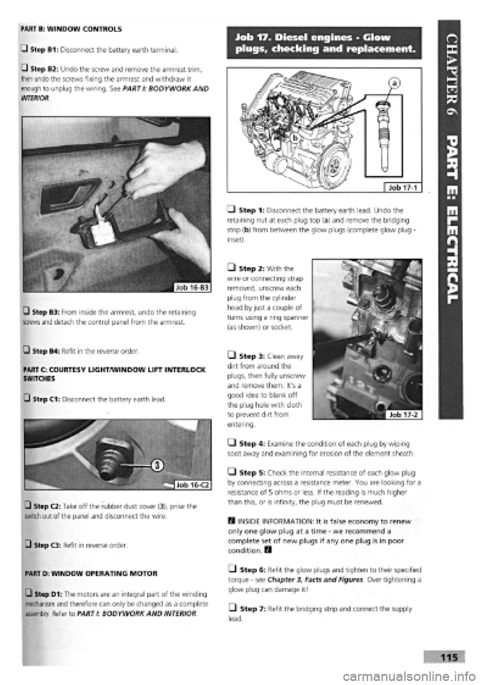
LI Step 1: Disconnect the battery earth lead. Undo the
retaining nut at each plug top (a) and remove the bridging
strip (b) from between the glow plugs (complete glow plug -
inset).
• Step 2: With the
wire or connecting strap
removed, unscrew each
plug from the cylinder
head by just a couple of
turns using a ring spanner
(as shown) or socket.
H INSIDE INFORMATION: It is false economy to renew
only one glow plug at a time
-
we recommend a
complete set of new plugs if any one plug is in poor
condition. E9
• Step 6: Refit the glow plugs and tighten to their specified
torque
-
see Chapter 3, Facts and Figures. Over tightening a
glow plug can damage it!
• Step 7: Refit the bridging strip and connect the supply
lead.
17-1
PART B: WINDOW CONTROLS
Q Step B1: Disconnect the battery earth terminal.
Q Step B2: Undo the screw and remove the armrest trim,
then undo the screws fixing the armrest and withdraw it
enough to unplug the wiring. See PARTI: BODYWORK AND
INTERIOR.
• Step 3: Clean away
dirt from around the
plugs, then fully unscrew
and remove them. It's a
good idea to blank off
the plug hole with cloth
to prevent dirt from
entering.
• Step 4: Examine the condition of each plug by wiping
soot away and examining for erosion of the element sheath.
• Step 5: Check the internal resistance of each glow plug
by connecting across a resistance meter. You are looking for a
resistance of 5 ohms or less. If the reading is much higher
than this, or is infinity, the plug must be renewed.
Q Step B4: Refit in the reverse order.
PART C: COURTESY LIGHT/WINDOW LIFT INTERLOCK
SWITCHES
Q Step C3: Refit in reverse order.
PART D: WINDOW OPERATING MOTOR
Q Step D1: The motors are an integral part of the winding
mechanism and therefore can only be changed as a complete
assembly. Refer to PART I: BODYWORK AND INTERIOR
Q Step B3: From inside the armrest, undo the retaining
screws and
detach the control panel from the armrest.
G Step C1: Disconnect the battery earth lead.
Q Step C2: Take off the rubber dust cover (3), prise the
switch out of the panel and disconnect the wire.
Page 122 of 171

• Step 22: Inspect the timing belt and if
-
• it is contaminated with any liquid,
• has damaged teeth,
• or frayed edges,
• or it has covered more than 30000 km,
-
fit a new one.
D INSIDE INFORMATION: Some FIAT mechanics
recommend that the belt is replaced as a matter of
course. The cost of a new belt compared to the cost
of a damaged engine, makes it a false economy not to
do so.
E9
Q Step 23: Place the timing belt over the sprockets,
keeping it tight on the run between the pump and camshaft.
Q Step 24: Push the adjusting pulley into the belt and nip
up the lock nut. Without the aid of the special tool, the
adjustment is roughly correct when you can twist the belt at
its longest point between thumb and finger through a quarter
turn (90 degrees).
• Step 25: Turn the engine two full revolutions, re-check
the timing and belt tension. Adjust if necessary and tighten
the adjusting pulley lock nut.
B INSIDE INFORMATION! CHECKING INJECTION
ADVANCE. This cannot be done without the use of a dial
gauge and special adapter to fit on the rear of the
pump. We strongly recommend that although your
engine may seem to be running well, you get it checked
by your FIAT dealer. B
Job 17. Diesel injectors -
remove and refit.
Q Step 1: Clean thoroughly around each injector to prevent
dirt from entering the cylinders when removing the injectors.
Q Step 2: Unscrew the fuel pipe union at the injector, using
a flare nut wrench (split ring spanner).
• Step 3: Loosen the union at the injection-pump-end of
each injector pipe. Disconnect the fuel-return unions at the
injector and move the return pipes away.
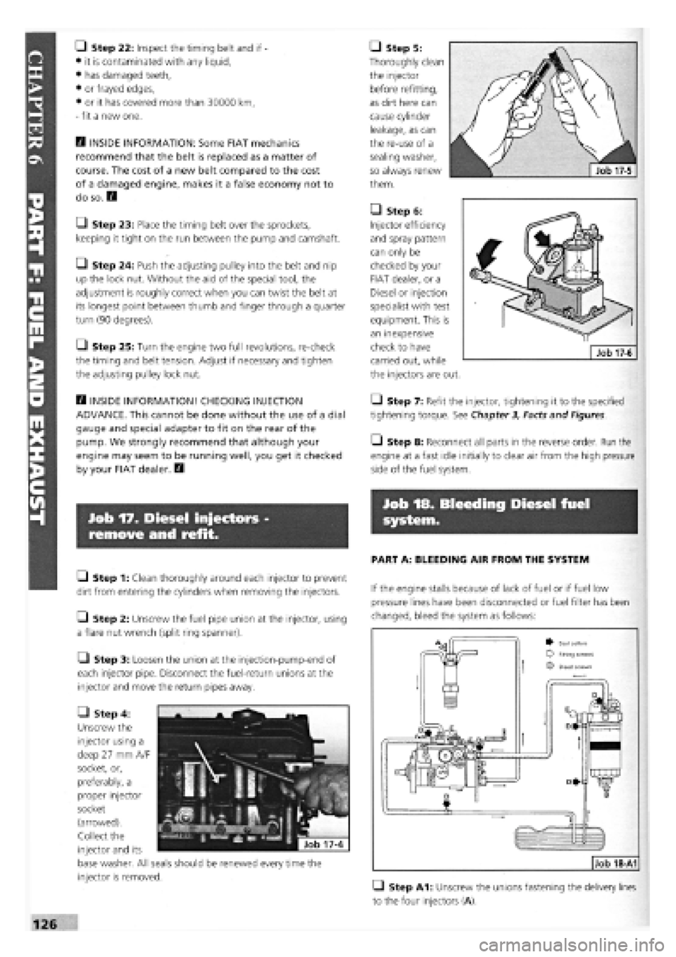
• Step 4:
Unscrew the
injector using a
deep 27 mm A/F
socket, or,
preferably, a
proper injector
socket
(arrowed).
Collect the
injector and its
base washer. All seals should be renewed every time the
injector is removed.
• Step 5:
Thoroughly clean
the injector
before refitting,
as dirt here can
cause cylinder
leakage, as can
the re-use of a
sealing washer,
so always renew
them.
• Step 6:
Injector efficiency
and spray pattern
can only be
checked by your
FIAT dealer, or a
Diesel or injection
specialist with test
equipment. This is
an inexpensive
check to have
carried out, while
the injectors are out.
• Step 7: Refit the injector, tightening it to the specified
tightening torque. See Chapter 3, Facts and Figures.
• Step 8: Reconnect all parts in the reverse order. Run the
engine at a fast idle initially to clear air from the high pressure
side of the fuel system.
Job 18. Bleeding Diesel fuel
system.
PART A: BLEEDING AIR FROM THE SYSTEM
If the engine stalls because of lack of fuel or if fuel low
pressure lines have been disconnected or fuel filter has been
changed, bleed the system as follows:
• Step A1: Unscrew the unions fastening the delivery lines
to the four injectors (A).
Job 18-A1
^ Seal collars Fifing screws
O Bleed screws
Page 129 of 171

Job 13. Rear shock absorbers and
coil springs - replacement.
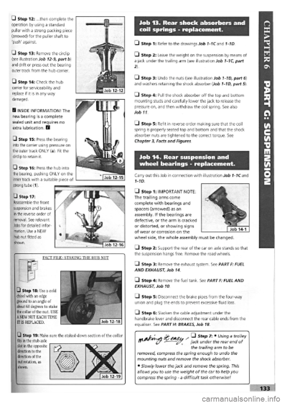
Q Step 12: ...then complete the
operation by using a standard
puller with a strong packing piece
(arrowed) for the puller shaft to
'push' against.
G Step 13: Remove the circlip
(see illustration Job
12-9,
part b)
and drift or press out the bearing
outer track from the hub carrier.
• Step 14: Check the hub
carrier for serviceability and
replace if it is in any way
damaged.
D INSIDE INFORMATION! The
new bearing is a complete
sealed unit and requires no
extra lubrication. D
• Step 15: Press the bearing
into the carrier using pressure on
the outer track ONLY (a). Fit the
circlip to retain it.
• Step 17:
Reassemble the front
suspension and brakes
in
the reverse order of
removal. See relevant
Jobs
for detailed infor-
mation. Use a NEW
hub nut fitted as
shown.
FACT FILE: STAKING THE HUB NUT
• Step 18: Use a cold
chisel
with an edge
ground to an angle of
about 60 degrees to stake
the
collar of the nut. USE
A
NEW NUT EACH TIME
IT IS REPLACED.
Q Step 19: Make sure the staked-down section of the collar
fits
in the stub axle
slot
in the opposite
direction to the
direction of the
nut
rotation, as
shown.
• Step 1: Refer to the drawings Job 1-1Cand 1-1D.
• Step 2: Leave the weight on the suspension by means of
a jack under the trailing arm (see illustration Job
1-1C,
part
• Step 3: Undo the nuts (see illustration Job
1-1D,
part
6)
and washers retaining the shock absorber (Job
1-1D,
part 5).
• Step 4: Pull the shock absorber off the top and bottom
mounting studs and carefully lower the jack to release the
pressure on, and then withdraw the coil spring. See also
Job 11
O Step 5: Refit in reverse order making sure that the coil
spring is properly seated top and bottom and that the shock
absorber nuts are tightened to the correct torque. See
Chapter
3,
Facts and Figures.
Job 14. Rear suspension and
wheel bearings - replacement.
Carry out this Job in connection with illustration Job
1-1C
and
1-1D.
• Step 1: IMPORTANT NOTE:
The trailing arms come
complete with bearings and
spacers (arrowed) as an
assembly. If the bearings are
defective, or the arm is cracked
or distorted, or showing signs
of wear or corrosion on the
wheel side, the whole assembly must be changed.
Q Step 2: Support the rear of the car on axle stands so that
the suspension hangs free. Remove the road wheels.
• Step 3: Remove the exhaust system. See PART F: FUEL
AND EXHAUST, Job 14.
• Step 4: Remove the fuel tank. See PART F: FUEL AND
EXHAUST, Job 10
• Step 5: Disconnect the brake pipes from the four-way
union and plug the ends to prevent excessive fluid loss.
Q Step 6: Slacken the cable adjustment under the
handbrake lever and disconnect the rear cable ends from the
equaliser. See PART H: BRAKES, Job 18
/ • Step 7: • Using a trolley
jack under the rear end of
the trailing arm to be
removed, compress the spring enough to undo the
mounting nuts and remove the shock absorber.
• Slowly lower the jack and remove the spring. This
allows you to use the weight of the car to help you
compress the spring
-
a difficult task otherwise!
Q Step 16: Press the hub into
the bearing, pushing ONLY on the
inner track with a suitable piece of
strong tube (1).
Page 151 of 171

IMPORTANT NOTE: Not all of the components listed here are fitted to all models.
CHAPTER 7
WIRING DIAGRAMS
IMPORTANT NOTE: Not all of the components listed here
are fitted to all models.
IMPORTANT NOTES:
3. We have sometimes shown the wiring diagram for a
'highest' spec, model, in the knowledge that 'lower'
spec, models are usually similar with the deletion of
certain components.
1. There are several hundred FIAT wiring diagrams for
the whole TIPO range. This is a representative selection,
covering the majority of applications. However, in the
event that your car's details are not covered here,
consult your nearest FIAT dealer.
2 All of the following are Tipo wiring diagrams. Tempra
saloons and estates are essentially similar.
4. 'EEC Stage 2 Engines' In late 1994, Tipo 1.4 and 2 -
Litre and Tempra 1.6 MPI vehicles were modified to suit
new emission regulations. These changes were NOT only
engine-related. Vehicles covered by this manual are Tipo
1.4 (with engine code no. 836A4.000) and Tempra 1.6
(with engine code 159B9.000). See Page 27 for location
of codes.
KEY:
1 Left front light cluster 2 Reversing light switch 3a Left horn 4 Electric cooling fan 5 Dual contact coolant thermal switch 6 Right longitudinal cable connection 7 Right front earth 8 Right front light cluster 9 Right horn 10 Screen/rear window washer pump 11 Left brake pad wear sensor 11A Right brake pad wear sensor 12 Ignition coil 12A Ignition coil with power module 12B Ignition coil with H.T. points 13 Digiplex electronic ignition control unit 13A Digiplex electronic ignition lead connection 13C Diagnostic socket for Digiplex electronic ignition 14 Left front earth 15 Battery earth 16 Engine coolant temperature sender unit 17 Battery 18 Ignition distributor 19 Sparkplug 20 Spark plug 21 Sparkplug 22 Spark plug 23 TDC sensor 24 Alternator 25 Oil pressure switch 26 Connector block 27 Brake fluid level sensor 28 Left side turn signal 30 Idle cut-out device 31 Starter motor 32 Throttle valve sensor 33 Pulse generator for speedometer signal 34 Windscreen wiper 35 Right side turn signal 36 P.T.C. resistor for heating fuel duct 37 Thermal switch for PTC 38 Vacuum sensor for vacuum gauge 39 Fuse and relay control unit E2 Turn signal and hazard warning light flasher E4 Fog light relay E5 Horn relay E6 Heated back window relay E7 Switch discharge connector E9 Windscreen wiper intermittent function E10 Rear fog light relay E11 Dipped beam relay E12 Main beam relay E13 Side light control relay E14 Central locking electronic control unit E1-E3-E8-E15-available (unused)
40 PTC resistor activation relay 41 20A fuse for inlet duct heater circuit 42 25A fuse for electric window ECU 43 Junction between facia cable and heater cable 44 Earth on left hand side of facia 45 Junction between facia cable and left front door
G Horn button H Windscreen wiper stalk I Back window wash/wipe selector L Heated rear windscreen switch M Rear screen wash/wipe switch N Windscreen wiper speed switch cables 56 Junction: facia cable and r.h. rear door cables Electric window control unit 57 Glove compartment light bulb Provision for left front speaker 58 Facia cable coupling with right front door cables Provision for left rear speaker 59 Facia cable coupling with right front door cables Supplementary earth point 60 Provision for right front speaker Instrument panel 60A Provision for right rear speaker A Direction indicators warning light 61 L.h. button for courtesy light and electric window B Side lights warning light 62 Junction between rear cable and left rear door C Main beam headlights warning light cables D Heated rear windscreen warning light 63 Junction between rear cable and left front door E Rear fog lights warning light cables E1 Fog lights warning light 64 Left front door lock motor and left front door F Hazard warning lights warning light open warning light G Battery recharging warning light 65 Left front electric window motor H Insufficient engine oil pressure warning light 66 Electric front window control buttons I Trip counter 67 Cigar lighter J Left brake lining wear warning light 68 Braking light switch J1 Seat belt undone warning light 69 Passenger compartment courtesy light K Handbrake on and low brake fluid level 69A Passenger compartment courtesy light with door warning light lock remote control receiver L Choke warning light 70 Hand brake warning light switch M ABS failure warning light 71 Passenger compartment ventilation fan switch N Instrument panel light bulbs 71A Passenger compartment ventilation control 0 Fuel level gauge 72 Passenger compartment ventilation fan speed P Coolant temperature gauge regulation resistor P1 Engine oil pressure gauge 73 Passenger compartment ventilation fan P2 Engine oil temperature gauge 74 Heater controls light bulbs Q Clock 75 Right front door lock motor and right front door R Heater plugs warning light open warning light S Speedometer 76 Right front electric window motor S1 Speed warning light 77 Right front electric window control button T Rev counter 78 R.h. button for courtesy lights and window U Trailer turn signal warning light 79 Luggage compartment lighting X Water in fuel filter warning light 80 Left rear earth Y Excessive turbocharging air pressure warning 80A Right rear earth light 81 Rear cable connection Y1 Lambda probe failure warning light 82 Left tail-light cluster Z Excessive automatic transmission fluid 83 Left rear door lock motor temperature warning light 84 Fuel level gauge Z1 Injection system failure warning light 85 Tailgate lock/release motor Ignition switch 86 Left number plate light Available for radio 87 Right number plate light Available for radio 88 Rear window wiper motor Hazard warning lights switch 89 Heated rear windscreen Stalk unit 90 Right tail-light cluster A Rear fog lights switch 91 Right rear door lock motor B Exterior lighting selector 92 Glow plug preheating system ECU c Control lighting bulb 93 Glow plugs D Light flasher button 94 Engine cooling fan first speed additional resistor E Turn signal stalk 95 30A fuse for engine cooling fan F Dipped/main beam headlight selector 96 Switch for automatic advance
155