1988 FIAT TEMPRA transmission oil
[x] Cancel search: transmission oilPage 76 of 171

Job 8. Petrol engine/transmission
- removal.
IMPORTANT NOTE: See PARTB: TRANSMISSION for
gearbox removal by itself.
H INSIDE INFORMATION! The complete engine/trans-
mission unit is removed and replaced from under the car
- and this applies to all types. Make sure you can raise
the front of the car high enough (and support it safely
and securely!) to allow the power unit to be pulled clear
from underneath, before starting work! 13
• Step 1: Remove the bonnet
-
see PARTI: BODY AND
INTERIOR, Job 1.
• Step 5:
Disconnect the
carburettor or
injector fuel lines,
choke and throttle
cables and hoses and
electrical connections
(arrowed).
Q Step 6: Disconnect the starter motor cables, HT leads,
fuel pump lines, sensors and electrical connectors arrowed.
Job
8-7
• Step 2: Disconnect the battery earth lead.
• Step 3: Drain the cooling system and the engine oil.
Disconnect all hoses shown.
• Step 7: Disconnect the clutch cable (3) or clutch slave
cylinder, if hydraulic, the earth cable (2) and the reversing
lights switch cable
(1)
from the top of the gearbox.
• Step 8: Disconnect the alternator cables.
Q Step 9: Slacken the front wheel bolts, raise the car and
support securely on axle stands. Remove the wheels.
• Step 10: Drain
the gearbox oil.
• Step 4:
Remove the air
filter-to-engine
connections
-
earlier type illus-
trated. (There are
some hose
connections
underneath on
the later type,
mounted on top
of the engine.) Disconnect the electrical connection and all
other hoses from the filter housing.
• Step 11:
Remove the buttons
(gearbox side,
arrowed) fixing the
dust shield to the
wheel arch on each
side.
Page 78 of 171

Q Step 23: Undo the mounting bolts, making sure the
power unit is supported safely as you take the last bolts out.
• Step 24: Lower the power unit to the ground and pull
clear.
Job 9. Petrol engine/transmission
- refitting.
Q INSIDE INFORMATION! The power unit can be refitted
by simply reversing the order of the operations for
removal as set out in the previous job. However, the
following points should receive your attention as the
work progresses. H
• Step 1: Refer to Chapter
3,
Facts and Figures for the
torque settings when refitting the various components.
• Step 2: If you don't have the FIAT too! (arrowed) to fit
the special Oetiker bands on the drive-shaft boots, use
woodworker's pincers, or fit new jubilee clips and screw them
reasonably tight.
• Step 3: Check the condition of all hoses and clips and
replace them if suspect.
• Step 4: Make sure all the electrical connections are
correctly made and are sound.
Q Step 5: Make sure the engine and gearbox have the
correct grades and quantities of oil. See Chapter
3,
Facts
and
Figures.
Q Step 6: Check that the cooling system has the correct
coolant mixture. See Chapter
3,
Facts and Figures.
• Step 7: Make a final check that nothing has been left un-
connected before starting up.
• Step 8: Run the engine up to working temperature and
then switch off. Check for leaks and re-check the fluid levels
when cold.
Page 79 of 171

Job 10. Petrol engine/
transmission (removed from car)
- separation.
Job 11. Petrol engine/
transmission (removed from car)
- reconnection.
• Clean the whole unit
with a proprietary
degreaser
-
and dry off
before
starting work.
•
This
makes these heavy components easier and safer
to
handle
and greatly reduces the risk of contami-
nation
when you strip them down.
Job 10-1
Q Step 1: Undo and remove the transmission mounting
bracket (b),
the starter motor (d) and unbolt and remove the
pressed
steel cover plate (a) from the lower face of the
flywheel housing. Undo the flywheel housing connecting bolts
and note
the position of the engine and transmission
mounting brackets and lifting eyes. The engine mounting arm
can be
left in place but the mounting itself (c) can now be
removed, if required.
Q Step 2: Support the weight of the transmission so that it
doesn't 'hang' on the clutch and withdraw it from the engine
in a
straight line.
Refer to Job
10
for the location of components referred to
here.
• Step 1: Offer the transmission to the engine. The input
shaft should slide easily through the splined hub of the driven
plate, provided that it is still centralised. See PART B:
TRANSMISSION Re-centre the clutch if necessary.
r ' «the input shaft and
- hub splines are not aligned,
ask a helper to turn the
crankshaft pulley nut while you apply gentle pressure
to bring the two units together.
• Step 2: Once the input shaft is properly engaged, use
two bolts, tightened evenly, to draw the units together.
DON'T force it! If the units don't come together easily,
separate them, check clutch centring and try again. Fit the
remaining bolts, not forgetting the lifting eyes and brackets.
• Step 3: Refit the flywheel housing cover plate and
mounting bracket.
Q Step 4: Refit the starter motor.
Job 12. Petrol engine.
Mountings - replacement.
See Job 8, Steps 21 to 23 for details of engine and trans-
mission mounting positions.
Change one mounting at
time.
• The others will help you
keep the power unit correctly positioned.
• Step 1: Support the weight of the power unit with a jack
until there is no upward or downward pressure on the
mounting to be changed.
Q Step 2: Undo the securing bolts and fit the new
mounting. Remove the supporting jack.
H INSIDE INFORMATION! If you unbolt the whole of
the rear mounting bracket, be sure to replace the two
bolts which go into the gearbox casing to prevent oil
leakage. D
Page 89 of 171

Job 17. Diesel engine.
Valve clearances - adjustment.
D INSIDE INFORMATION! After carrying out Job 16,
valve clearance measurement and adjustment is now
needed. Both measurement and shim replacement are
carried out in the same manner as for the petrol engine
(.Job
7), so refer to this and also to Chapter 3, Facts
and Figures for specifications. B
Job 18. Diesel engine - removal.
moving parts with engine oil during assembly. See Chapter 3,
Facts
and Figures for specified tightening torques.
luei suppiy diiu leium pipe;>
at the injection pump...
• Step 9: ...and the stop
control supply cable. Also
disconnect the cable from
the injection pump hydraulic
advance control sensor and
the alternator cables.
• Step 10:
Disconnect the oil
feed and return
pipes between the
thermostatic valve
and the radiator
and tie clear.
I
This should
be read in connection with Job 8
Q INSIDE INFORMATION! • The turbo and non-turbo
diesel engines are essentially similar.
• The under-bonnet scene is in some ways different
because of the extra plumbing required when a turbo is
fitted.
• Locations and shapes of various items may differ, or
not exist at all on the non-turbo unit.
• As most complexity is found with the turbo engine,
I
the
following illustrations are mainly of this version.
• The power units are removed from under the car,
therefore make sure you can raise the car enough to
achieve this. Support the car firmly and safely on axle
stands. D
Q Step 1: Disconnect the negative lead from the battery
and drain
the cooling system. Q Step 2: Remove the bonnet lid.
• Step 3: Drain the transmission oil.
Q Step 4: Disconnect and remove all pipes and hoses.
Q Step 5: Undo all electrical connection and label them
with masking
tape. Write matching numbers on each male
and female
connection to assist reconnection, later.
Q Step 6: Disconnect the power steering pump pipes
(where fitted),
catching any spilt fluid and tie them clear. See
Job 14.
• Step 7: Part the
connection for the
electronic
speedometer
magnetic impulse
generator
(when fitted).
Q Step 11: Disconnect the clutch cable, adjacent earth lead
and reversing light switch other cable connection from the top
of the gearbox.
• Step 12: Disconnect the leads from the oil pressure
warning light from the oil filter mounting, and the oil level
warning light switch.
• Step 13: From under the car, remove the exhaust front
section from the manifold and from its support brackets.
O Step 14: Remove the front road wheels and the access
panel from each wheel housing.
• Step 15: Remove the brake pad wear sensor cables,
when fitted.
Q Step 16A: On the turbo version, undo the six 'Allen'
screws securing the inboard end of each drive-shaft. Undo the
two pinch bolts that fix each stub axle to the suspension struts
and pull them clear. Ease the drive-shafts clear of the trans-
mission casing
-
take care
not to
damage the
protective
boots.
Page 91 of 171
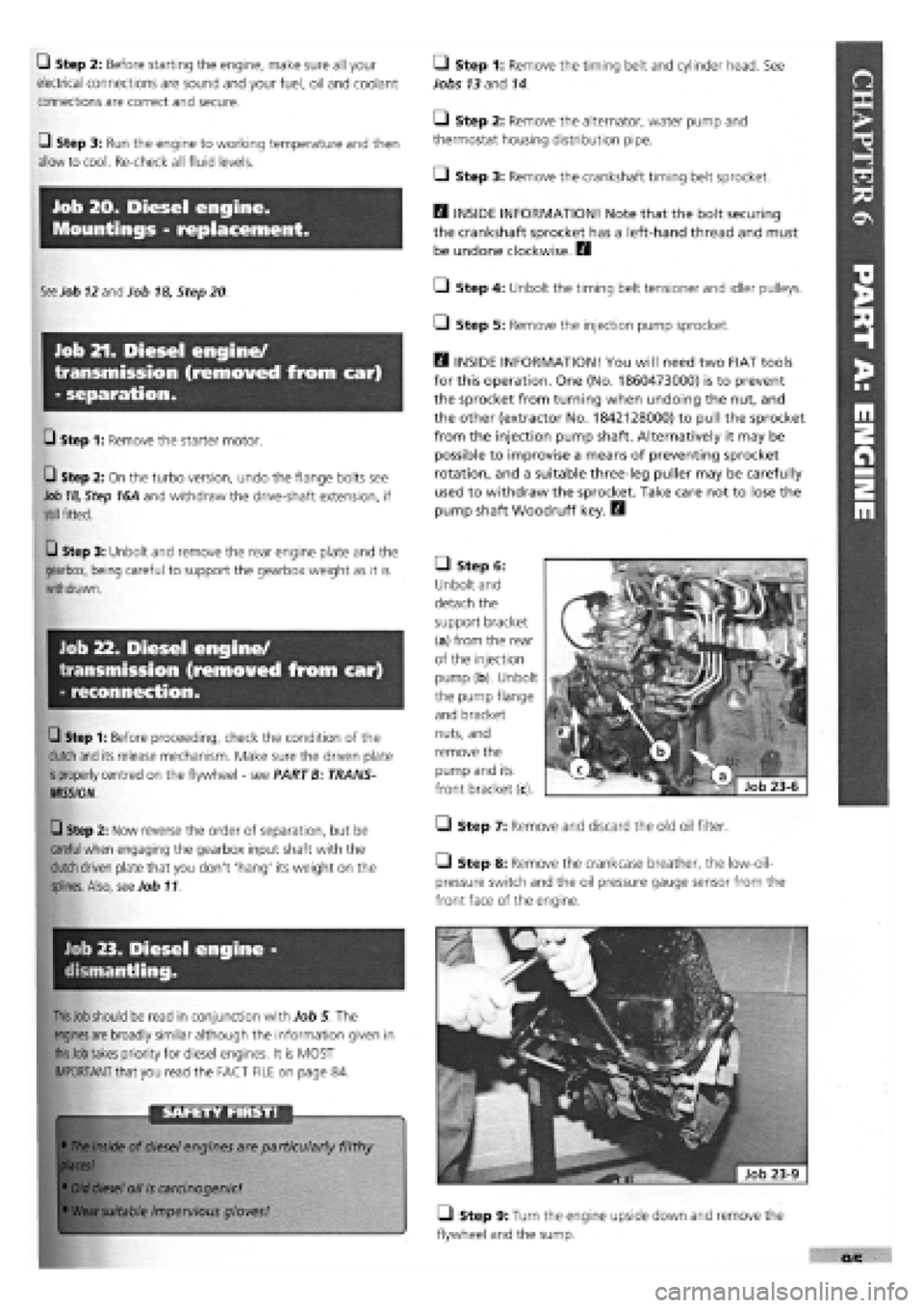
Q Step 2: Before starting the engine, make sure all your
electrical connections are sound and your fuel, oil and coolant
connections are correct and secure.
Q Step 3: Run the engine to working temperature and then
allow to cool. Re-check all fluid levels.
Job 20. Diesel engine.
Mountings - replacement.
See
Job
12
and Job
18,
Step 20
Job 21. Diesel engine/
transmission (removed from car)
- separation.
Q Step 1: Remove the starter motor.
• Step 2: On the turbo version, undo the flange bolts see
Job
18,
Step 16A and withdraw the drive-shaft extension, if
still
fitted.
Q Step 3: Unbolt and remove the rear engine plate and the
gearbox, being careful to support the gearbox weight as it is
withdrawn.
Job 22. Diesel engine/
transmission (removed from car)
- reconnection.
Q Step 1: Before proceeding, check the condition of the
clutch and
its release mechanism. Make sure the driven plate
is
properly centred on the flywheel
-
see PART B: TRANS-
MISSION.
Q Step 2: Now reverse the order of separation, but be
careful when
engaging the gearbox input shaft with the
clutch
driven plate that you don't 'hang' its weight on the
splines.
Also,
see
Job 11.
Job 23. Diesel engine -
dismantling.
This Job should
be read in conjunction with Job 5 The
engines are
broadly similar although the information given in
this Job takes
priority for diesel engines. It is MOST
IMPORTANT that you read the FACT FILE on page 84.
SAFETY FIRST!
•
The inside
of diesel engines are particularly filthy
places!
•
Old diesel
oil
is
carcinogenic!
•
Wear suitable
impervious gloves!
I
• Step 1: Remove the timing belt and cylinder head. See
Jobs
13
and 14.
Q Step 2: Remove the alternator, water pump and
thermostat housing distribution pipe.
• Step 3: Remove the crankshaft timing belt sprocket.
Q INSIDE INFORMATION! Note that the bolt securing
the crankshaft sprocket has a left-hand thread and must
be undone clockwise. D
• Step 4: Unbolt the timing belt tensioner and idler pulleys.
• Step 5: Remove the injection pump sprocket.
Q INSIDE INFORMATION! You will need two FIAT tools
for this operation. One (No. 1860473000) is to prevent
the sprocket from turning when undoing the nut, and
the other (extractor No. 1842128000) to pull the sprocket
from the injection pump shaft. Alternatively it may be
possible to improvise a means of preventing sprocket
rotation, and a suitable three-leg puller may be carefully
used to withdraw the sprocket. Take care not to lose the
pump shaft Woodruff key. B
• Step 6:
Unbolt and
detach the
support bracket
(a) from the rear
of the injection
pump (b). Unbolt
the pump flange
and bracket
nuts, and
remove the
pump and its
front bracket (c).
• Step 7: Remove and discard the old oil filter.
Step 8: Remove the crankcase breather, the low-oil-
pressure switch and the oil pressure gauge sensor from the
front face of the engine.
• Step 9: Turn the engine upside down and remove the
flywheel and the sump.
Page 94 of 171

U Step 12: Fit a new seal to the front cover/oil pump
assembly, unless a new pump is being fitted, and install with a
new gasket, lightly oiling both gasket and seal. Align the cover
with the sump support plate.
PISTON CONNECTING RODS ASSEMBLIES
• Step 13:
H INSIDE
INFORMATION!
Refer to the illus-
tration and note
that the piston
should be fitted
to the connecting
rod so that when
viewed from the
timing end the
crown lift (1) is
on the right
hand/injection
pump (2) side. At
the same time,
the bore numbers
stamped on the connecting rod (3) should face left, the
opposite side. The piston pins are an interference fit in
the pistons and can be tapped into position using an
ordinary drift and secured with circlips. H
Refer to Job 6. Steps 11 to
18,
for installation procedures.
Q Step 14: Refit the oil pump pick-up and return pipes.
• Step 15: Refit the sump using a new gasket. Check that
the drain plug is tight.
• Step 16: Complete the reassembly by fitting all the
external components in the reverse order of removal. Refer to
Job
15
for cylinder head refitting.
• Step 17: Reconnect the engine to the transmission. See
Job
22
• Step 18: Refit the complete unit to the car. See Job
19
• Step 19: Bleed the fuel system. See PART F: FUEL AND
EXHAUST
Q INSIDE INFORMATION! Bleeding the fuel system
involves turning the engine on the starter. This should
allow it to gain oil pressure before 'firing up', but check
that the oil light has gone out as soon as the engine
starts. H
Q Step 20: Allow the engine to run at 'fast idle' until it
reaches working temperature and switch off. Allow it to cool
and check the oil and coolant levels and look for any leaks.
Q Step 21: Avoid over-rewing or overloading the engine
during its settling down period of 600 miles. We recommend
an oil and filter change at this mileage
-
this will help to
extend the life of your engine.
PART B: TRANSMISSION
PART B: Contents
Job 1. Transmission removal (with engine in car).
Job 2. Transmission refitting (with engine in car).
Job 3. Clutch
-
replacement.
Job 4. Clutch cable
-
replacement.
Job 5. Gear lever and linkage
-
removal and refitting.
Job 6. Kickdown cable (automatic transmission)
-
replacement.
Job 7. Kickdown cable (automatic transmission)
-
adjustment.
Job 8. Automatic gear selector control cable
-
replacement.
Job 9. Drive-shaft
-
removal and refitting.
Job 10. Drive-shaft (outer) constant velocity joint
-
replacement.
Job 11. Drive-shaft inner spider joint
-
replacement.
Job 12. Drive-shaft damper
-
replacement.
Job 13. Front hub/bearings
-
replacement.
Job 14. Hydraulic clutch components.
Job 1. Transmission removal
(with engine in car).
IMPORTANT NOTE: This operation is for cars fitted with
the 1400 and 1600cc petrol engines and non-turbo diesel
engines. For the 1930cc turbo diesel engined version the
complete power unit must be removed and then
separated. See PART A, Jobs 18, 19, 21 and 22 for the
removal of several of the ancillaries detailed here.
• Step 1:
Before
starting
work, ensure
that you can
support the
car suffi-
ciently high
off the ground for the gearbox to be removed from beneath.
Make sure that the gearbox-end of the engine is supported
from above the car, or from beneath. You may be able to
fabricate your own version of this FIAT tool (arrowed).
Page 95 of 171

• Step 2: Remove the bonnet. Disconnect and remove the
battery.
0 Step 3: Drain the oil from the transmission.
0 Step 4: Disconnect the clutch cable or remove the slave
cylinder, if hydraulic, from the top of the gearbox.
• Step 13: Disconnect the
gearchange rods at the gearbox
(arrowed).
O Step 14: Remove the trans-
mission mounting and bracket
assembly.
Job 2. Transmission refitting
(with engine in car).
/ a 5tep1S: • SLjpp°n the
'' £/ gearbox in such a way that
when disconnecting, it can
be withdrawn smoothly and without 'hanging' on the
engine. A trolley jack might do the job nicely.
• Step 16:
Undo the gearbox
to engine fixing
bolts...
• Step 17: ...slide the
box back until it's clear of
the clutch and lower it to
the ground using a
hydraulic stand or trolley
jack.
IMPORTANT NOTE: Refer to PART A: ENGINE, Jobs 8
and 9 in connection with this Job.
• Step 1: Refitting is the reverse of the removal work
carried out in Job 1 but bear in mind the following:
Q Step 2: Centralise the clutch driven plate, if it has been
disturbed. See Job 3.
• Step 3: NON-HYDRAULIC CLUTCHES ONLY. Adjust the
clutch cable. See Job 4
Q Step 6: Raise the front of the car and support securely on
axle stands.
Remove the road wheels and the previously
slackened hub nuts.
Q Step 7: Remove the wheel arch protective shields.
Q Step 8: Disconnect the speedometer cable from the
gearbox. (If digital instrumentation, disconnect the wiring
from
the sender unit.)
Q Step 9: Disconnect and remove the starter motor and
unplug
the reverse light connector and the earth lead from
the
transmission housing.
Q Step 10: Undo the trackrod ends securing nuts and use a
suitable 'splitter' tool to part the balljoints from the steering
arms.
Slacken the drive-shaft inner boot securing clips. Undo
the pinch
bolts fixing the stub axles to the suspension struts,
pull
the stub axles clear and extract the drive-shafts.
0 Step 11: Support the engine at the gearbox end, just
taking
the weight as described in Step 1.
Q Step 12: Remove the central power unit support (a), the
flywheel guard (b) and the exhaust bracket (c).
• Step 5: With
the
car
still
on the
ground, loosen
the nuts
fixing the
constant velocity
joints
to the hubs.
These require an
enormous force
to be
tightened or
released (see
Chapter 3,
Facts and Figures) and they will have been
staked. There is a severe risk of pulling the car off supports if
you
attempt to undo these nuts while the car is raised off the
ground. Slacken the front wheel nuts.
Job 1-14
Page 96 of 171

• Step 4: Refill the gearbox with the correct grade and
quantity of FL oil. See Chapter
3,
Facts and Figures.
Section as appropriate, for the replacement of the rear
crankshaft seal. B
—1 Step 5: When the brake calipers have been refitted,
pump the brake pedal until its normal solid feel is restored.
• Step 6: Use a self-grip wrench to reconnect the gear rod
balls and sockets. Use new drive-shaft nuts, tightened to the
correct torque and staked into the shaft grooves with a
punch. See Job 9.
Job 3. Clutch - replacement.
1 - cover plate 2 - driven plate 3 - release bearing
4 - retaining bolt 5 - spring washer
;
Job 3-1
Q Step 1: These first three numbered parts are the parts
you will need to obtain, from your FIAT dealership.
FACT FILE: CLUTCH COMPONENTS
• We strongly recommend that all three
main components: clutch cover, driven
plate and release bearing are replaced
after a high mileage, ensuring longer life
and smoother operation.
• If one is worn, they are all likely to be, so save
yourself another big stripdown in the near future!
LI Step 2: Remove the transmission. See Job 1.
• Step 3: Unscrew the clutch cover bolts (see illustration
Job
3-1,
part 4) progressively until the spring pressure is
released, then remove the bolts. Ease the cover (part 1) off its
dowels and catch the driven plate {part 2) as it falls.
• Step 6: Check the surface of the flywheel that mates
with the clutch, for scoring, or significant micro cracking
caused by excessive head generated by clutch slip. Replace the
flywheel if in doubt.
7ZJ
• Step 7: Check the
release fork pivot, inside
the bellhousing, for wear
Replace the bushes (see
inset) if necessary, lubri-
cating with a small
quantity of molybdenum
disulphide grease.
• Step 8: Replace the bush
(a) by removing the circlip (b)
from the lever shaft (d). Note
the position of the arm (c) on
the splines for refitting and
slide it off. Prise the bush out
using a screwdriver. Lubricate
the new bush with a small
quantity of molybdenum disul-
phide grease and install. Refit
the arm to the fork control
shaft (d) with a new circlip.
Refit the release bearing (e).
• Step 9: Clean any oil (or the protective film) from the
clutch cover and flywheel faces.
• Step 10: Offer the driven plate to the flywheel with the
side having the greatest hub projection facing outwards.
• Step 11: Locate the clutch cover on the flywheel dowels
and screw in the fixing bolts finger tight.
• Step 12: Use an aligning tool to make sure that the
clutch is centralised, otherwise the gearbox will not relocate
on the engine and damage can be caused to the centre plate.
B INSIDE INFORMATION: There is no spigot bush or
bearing in the crankshaft end, but there is an inden-
tation which you can 'feel' with a normal clutch
alignment tool allowing you to centralise the driven
plate between the clutch cover release fingers. B
• Step 5: B INSIDE
INFORMATION: Check
the inside of the
clutch bellhousing for
contamination by oil.
This indicates a leak
from either the
crankshaft rear seal
or the gearbox input
shaft seal (illus-
trated). A faulty seal should be replaced without delay.
Oil can cause judder and slip. Here, the seal (inset) is
being replaced. See PART A: ENGINE, Job 21 for the
position of the rear crankshaft seal. B
• Step 4: B INSIDE
INFORMATION! Check
the inside of the clutch
bell housing for conta-
mination by oil. This
indicates a leak from
either the crankshaft
rear seal or the
gearbox input shaft
seal. Oil can cause
judder and slip.
Replace the gearbox seal by removing the screws holding
in the thrust bearing sleeve (a), prising out the old and
fitting a new seal (b). See PART A: Petrol or Diesel