1988 FIAT TEMPRA oil level
[x] Cancel search: oil levelPage 41 of 171
IMPORTANT NOTE: Take care not to allow any dirt or grit
to get into the gearbox.
• Job 19. Check driveshaft gaiters.
45
B INSIDE INFORMATION: Make sure you have a 10 mm
Allen key that will fit, before you start. There's very little
room between gearbox and subframe. B
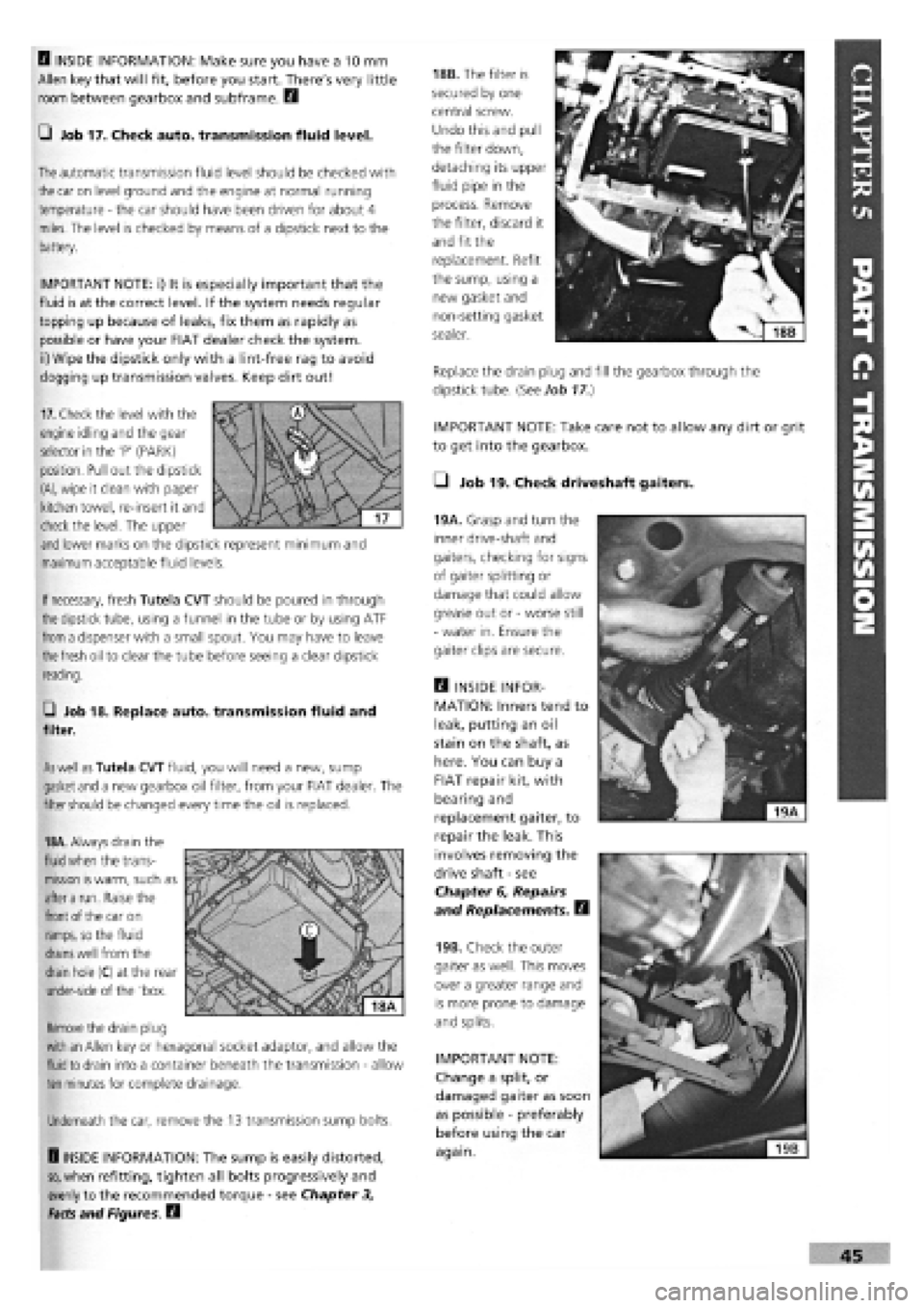
Q Job 17. Check auto, transmission fluid level.
The
automatic transmission fluid level should be checked with
the
car on level ground and the engine at normal running
temperature
-
the car should have been driven for about 4
miles. The level is checked by means of a dipstick next to the
battery.
IMPORTANT NOTE: i) It is especially important that the
fluid is at the correct level. If the system needs regular
topping up because of leaks, fix them as rapidly as
possible or have your FIAT dealer check the system,
ii) Wipe the dipstick only with a lint-free rag to avoid
clogging up transmission valves. Keep dirt out!
18B. The filter is
secured by one
central screw.
Undo this and pull
the filter down,
detaching its upper
fluid pipe in the
process. Remove
the filter, discard it
and fit the
replacement. Refit
the sump, using a
new gasket and
non-setting gasket
sealer.
Replace the drain plug and fill the gearbox through the
dipstick tube. {See Job
17.)
19A. Grasp and turn the
inner drive-shaft and
gaiters, checking for signs
of gaiter splitting or
damage that could allow
grease out or
-
worse still
-
water in. Ensure the
gaiter clips are secure.
Q INSIDE INFOR-
MATION: Inners tend to
leak, putting an oil
stain on the shaft, as
here. You can buy a
FIAT repair kit, with
bearing and
replacement gaiter, to
repair the leak. This
involves removing the
drive shaft
-
see
Chapter 6, Repairs
and Replacements. B
19B. Check the outer
gaiter as well. This moves
over a greater range and
is more prone to damage
and splits.
IMPORTANT NOTE:
Change a split, or
damaged gaiter as soon
as possible
-
preferably
before using the car
again.
If
necessary,
fresh Tutela CVT should be poured in through
the
dipstick tube, using a funnel in the tube or by using ATF
from
a dispenser with a small spout. You may have to leave
the fresh
oil to clear the tube before seeing a clear dipstick
reading.
G Job 18. Replace auto, transmission fluid and
filter.
As well as
Tutela CVT fluid, you will need a new, sump
gasket
and
a new gearbox oil filter, from your FIAT dealer. The
filter
should
be changed every time the oil is replaced.
18A.
Always drain the
fluid when
the trans-
mission
is
warm, such as
after a
run. Raise the
front
of the car on
ramps,
so the fluid
drains well
from the
drain
hole (C) at the rear
under-side of the 'box.
Remove
the drain plug
with an
Allen key or hexagonal socket adaptor, and allow the
fluid to
drain into a container beneath the transmission
-
allow
ten
minutes for complete drainage.
Underneath the car, remove the 13 transmission sump bolts.
H INSIDE INFORMATION: The sump is easily distorted,
so,
when refitting, tighten all bolts progressively and
evenly to the recommended torque
-
see Chapter 3,
Facts and Figures. B
17.
Check the level with the
engine idling and the gear
selector in the 'P' (PARK)
position. Pull out the dipstick
(A),
wipe it clean with paper
kitchen towel, re-insert it and
check the level. The upper
and
lower marks on the dipstick represent minimum and
maximum acceptable fluid levels.
Page 54 of 171
each track rod end (TRE). Also, look out for a split gaiter.
Replace the TRE if the gaiter is split, or it will rapidly fail.
E3 INSIDE INFORMATION: Try placing your hand over the
TRE as the steering is moved. If there are any signs of
wear, replace the TRE. Q
STEERING COLUMN
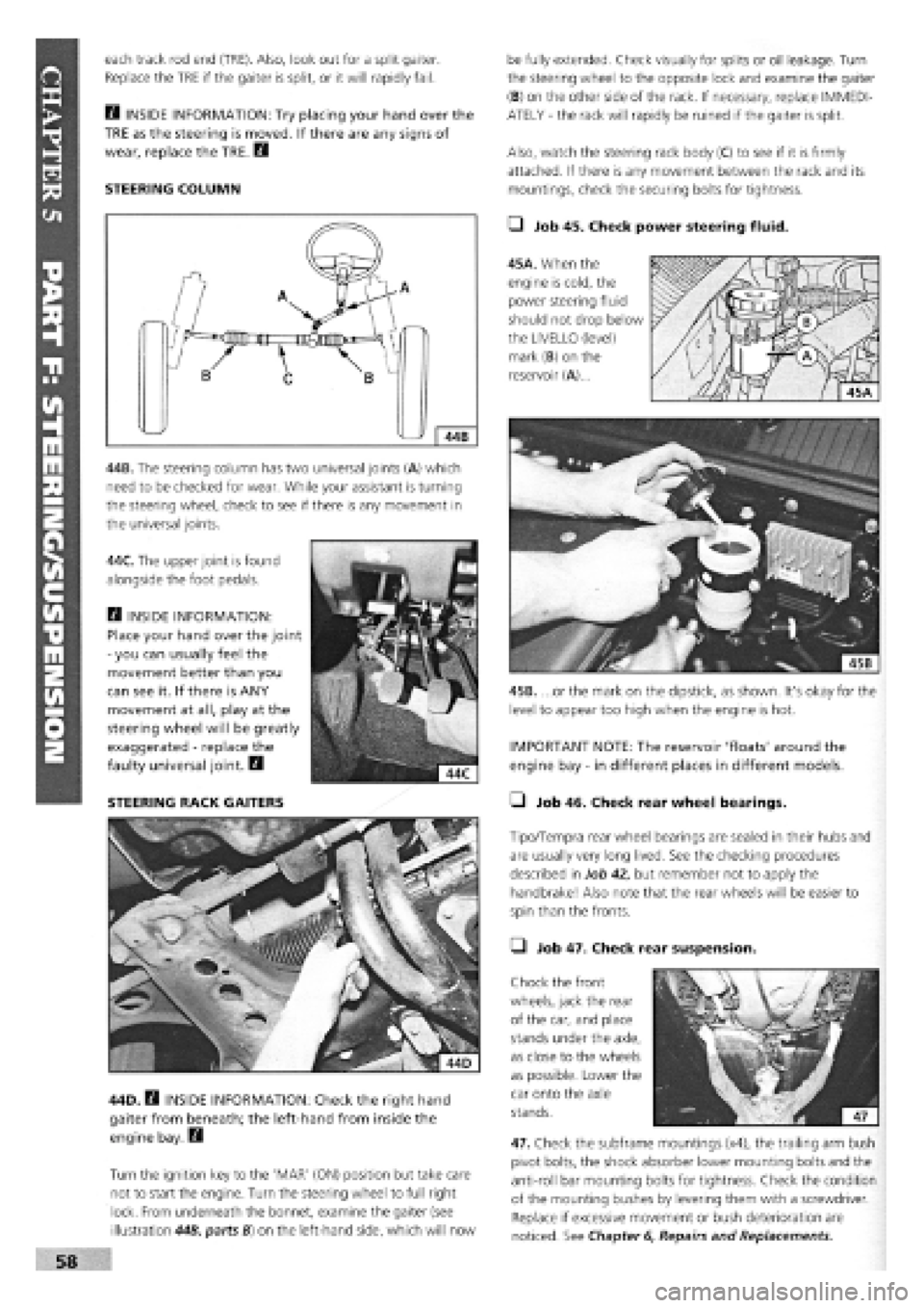
44B. The steering column has two universal joints (A) which
need to be checked for wear. While your assistant is turning
the steering wheel, check to see if there is any movement in
the universal joints.
44C. The upper joint is found
alongside the foot pedals.
Q INSIDE INFORMATION:
Place your hand over the joint
-
you can usually feel the
movement better than you
can see it. If there is ANY
movement at all, play at the
steering wheel will be greatly
exaggerated
-
replace the
faulty universal joint. B
STEERING RACK GAITERS
44D. B INSIDE INFORMATION: Check the right hand
gaiter from beneath; the left-hand from inside the
engine bay. Q
Turn the ignition key to the 'MAR' (ON) position but take care
not to start the engine. Turn the steering wheel to full right
lock. From underneath the bonnet, examine the gaiter (see
illustration 44B, parts B) on the left-hand side, which will now
be fully extended. Check visually for splits or oil leakage. Turn
the steering wheel to the opposite lock and examine the gaiter
(B) on the other side of the rack. If necessary, replace IMMEDI-
ATELY
-
the rack will rapidly be ruined if the gaiter is split.
Also, watch the steering rack body (C) to see if it is firmly
attached. If there is any movement between the rack and its
mountings, check the securing bolts for tightness.
• Job 45. Check power steering fluid.
45A. When the
engine is cold, the
power steering fluid
should not drop below
the LIVELLO (level)
mark (B) on the
reservoir (A)...
45B. ...or the mark on the dipstick, as shown. It's okay for the
level to appear too high when the engine is hot.
IMPORTANT NOTE: The reservoir 'floats' around the
engine bay
-
in different places in different models.
• Job 46. Check rear wheel bearings.
Tipo/Tempra rear wheel bearings are sealed in their hubs and
are usually very long lived. See the checking procedures
described in Job 42, but remember not to apply the
handbrake! Also note that the rear wheels will be easier to
spin than the fronts.
• Job 47. Check rear suspension.
Chock the front
wheels, jack the rear
of the car, and place
stands under the axle,
as close to the wheels
as possible. Lower the
car onto the axle
stands.
47. Check the subframe mountings (x4), the trailing arm bush
pivot bolts, the shock absorber lower mounting bolts and the
anti-roll bar mounting bolts for tightness. Check the condition
of the mounting bushes by levering them with a screwdriver.
Replace if excessive movement or bush deterioration are
noticed. See Chapter
6,
Repairs and Replacements.
Page 58 of 171
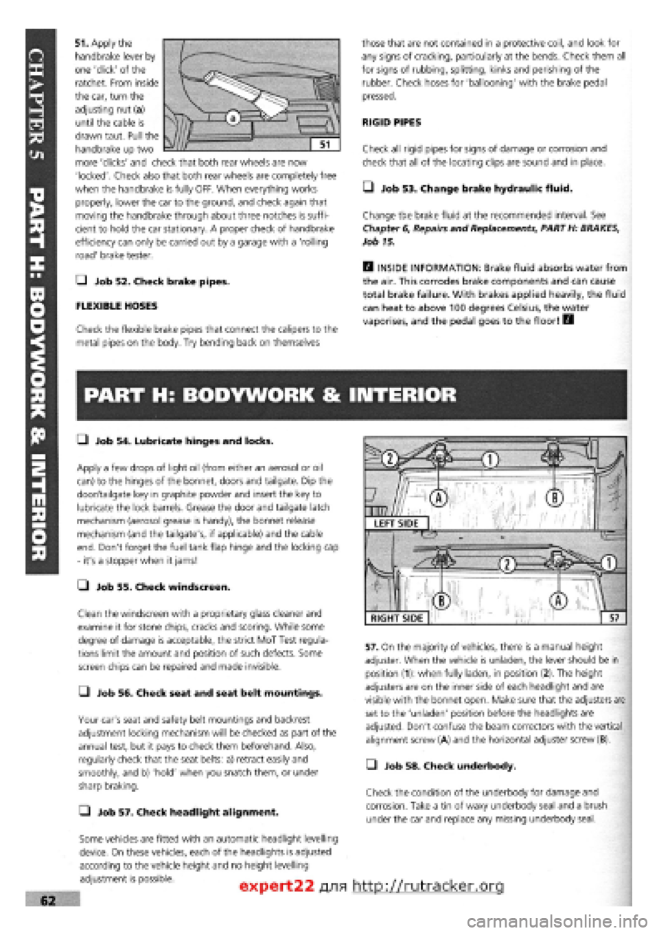
51. Apply the
handbrake lever by
one 'click' of the
ratchet. From inside
the car, turn the
adjusting nut (a)
until the cable is
drawn taut. Pull the
handbrake up two
more 'clicks' and check that both rear wheels are now
'locked'. Check also that both rear wheels are completely free
when the handbrake is fully OFF. When everything works
properly, lower the car to the ground, and check again that
moving the handbrake through about three notches is suffi-
cient to hold the car stationary. A proper check of handbrake
efficiency can only be carried out by a garage with a 'rolling
road' brake tester.
Q Job 52. Check brake pipes.
FLEXIBLE HOSES
Check the flexible brake pipes that connect the calipers to the
metal pipes on the body. Try bending back on themselves
those that are not contained in a protective coil, and look for
any signs of cracking, particularly at the bends. Check them all
for signs of rubbing, splitting, kinks and perishing of the
rubber. Check hoses for 'ballooning' with the brake pedal
pressed.
RIGID PIPES
Check all rigid pipes for signs of damage or corrosion and
check that all of the locating clips are sound and in place.
• Job 53. Change brake hydraulic fluid.
Change the brake fluid at the recommended interval. See
Chapter
6,
Repairs and Replacements, PART H: BRAKES,
Job 15.
H INSIDE INFORMATION: Brake fluid absorbs water from
the air. This corrodes brake components and can cause
total brake failure. With brakes applied heavily, the fluid
can heat to above 100 degrees Celsius, the water
vaporises, and the pedal goes to the floor! B
PART H: BODYWORK & INTERIOR
• Job 54. Lubricate hinges and locks.
Apply a few drops of light oil (from either an aerosol or oil
can) to the hinges of the bonnet, doors and tailgate. Dip the
door/tailgate key in graphite powder and insert the key to
lubricate the lock barrels. Grease the door and tailgate latch
mechanism (aerosol grease is handy), the bonnet release
mechanism (and the tailgate's, if applicable) and the cable
end. Don't forget the fuel tank flap hinge and the locking cap
- it's a stopper when it jams!
• Job 55. Check windscreen.
Clean the windscreen with a proprietary glass cleaner and
examine it for stone chips, cracks and scoring. While some
degree of damage is acceptable, the strict MoT Test regula-
tions limit the amount and position of such defects. Some
screen chips can be repaired and made invisible.
• Job 56. Check seat and seat belt mountings.
Your car's seat and safety belt mountings and backrest
adjustment locking mechanism will be checked as part of the
annual test, but it pays to check them beforehand. Also,
regularly check that the seat belts: a) retract easily and
smoothly, and b) 'hold' when you snatch them, or under
sharp braking.
Q Job 57. Check headlight alignment.
Some vehicles are fitted with an automatic headlight levelling
device. On these vehicles, each of the headlights is adjusted
according to the vehicle height and no height levelling
adjustment is possible.
57. On the majority of vehicles, there is a manual height
adjuster. When the vehicle is unladen, the lever should be in
position (1): when fully laden, in position (2). The height
adjusters are on the inner side of each headlight and are
visible with the bonnet open. Make sure that the adjusters are
set to the 'unladen' position before the headlights are
adjusted. Don't confuse the beam correctors with the vertical
alignment screw (A) and the horizontal adjuster screw (B).
• Job 58. Check underbody.
Check the condition of the underbody for damage and
corrosion. Take a tin of waxy underbody seal and a brush
under the car and replace any missing underbody seal.
expert22 fl/ia http://rutracker.org
RIGHT SIDE
Page 67 of 171

G Step 6: Fit the four or five smaller bolts, according to
model (see illustration Job
3-4,
arrowed) close to the spark
plug holes, and tighten to their specified torque. See Chapter
3, Facts
and Figures.
G Step 7: All items previously removed in Job 2 can now be
fitted in reverse order. When connecting the exhaust always
use a
new flange gasket.
G Step 8: Ensure that all connections are sound and secure.
G Step 9: All items previously removed in Job 2 can now be
fitted in reverse order. Refer to Job
1
when fitting the timing
belt.
When connecting the exhaust always use a new flange
gasket.
G Step 10: Ensure that all connections are sound and
secure.
G Step 11: Top up the cooling system with the correct
50/50
solution of FL 'Tutela' anti-freeze solution. Check the
oil
level.
• Step 5: Clean and check all components for wear and
signs of 'scuffing'.
B INSIDE INFORMATION! If the camshaft is changed, the
followers should be changed as well. If the bores in the
housing have 'picked up', these cannot be machined and
the housing should be replaced together with new cam
followers. B
• Step 6: Refit the camshaft to the cam housing and insert
the cam followers and shims in their correct bores, using
grease to keep them in place. For adjustment of valve clear-
ances see Job 7.
2 ZeASt, s * when re'inserti"9the
nfW^c/ !X J?^ camshaft, it can be difficult
to get the camshaft fully in
to its end seal. DON'T try hammering it in
-
all you'll
do is damage the seal. Lubricate the seal with fresh
engine oil, insert the camshaft until it is aligned with
and just touching the seal. Push the camshaft with a
twisting motion until it eases its way into the seal.
Job 4. Petrol engine.
Cylinder head - dismantling and
overhauling.
G Step 3: Remove the
cam
followers and shims
from
the housing,
keeping them in the
correct order for refitting
in the
same positions.
Refer to the illustration Job
2-1
for the components covered
in this
Job.
G Step 1: Remove the camshaft housing from the cylinder
head. See Job 2.
G Step 2: Remove the
camshaft housing end
plate
(or the distributor
mounted in the same
place on
certain models).
G Step 4: Slide the
camshaft out, taking
care not to damage the
camshaft bearings with
the cam
lobes.
• Step 7: Use a suitable valve spring compressor to
compress each spring in turn to allow the removal of the split
collets from the valve stems. Inexpensive valve spring
compressors are readily available from auto, accessory stores.
Take care not to lose the collets when releasing the spring
compressor.
Q Step 9: The valve spring caps, springs and spring seats
can all be lifted clear and the valves withdrawn from their
guides.
• Step 8:
These are the
items to be
removed once
the valve is
withdrawn.
1 - flat washer 2 - lower cap 3 - inner spring
4 - outer spring 5 - upper cap 6 - collets Job 4-8
Page 75 of 171
G Step 43: Stop the engine and allow it to cool, check the
oil
and coolant levels and look for any leaks.
G Step 44: Avoid over-rewing or overloading the engine
during its settling down period of 600 miles. We recommend
an oil
and filter change at this mileage
-
this will help to
extend the life of your new engine.
Job 7. Petrol engine.
Valve clearances - adjustment.
0 INSIDE INFORMATION! Adjustment should always be
made with the engine cold. B
G Step 1: Remove the camshaft cover and the spark plugs.
Jack up a front wheel and engage top gear. Turning the wheel
will rotate the engine and therefore the camshaft. If the
engine
is
out of the car, use a socket and long lever on the
crankshaft pulley nut. If the cylinder head is detached, turn
the
camshaft belt sprocket, by hand.
G Step 2: The inlet and exhaust valves use different clear-
ances
which are checked when each cam lobe is pointing
directly away from its follower. See Chapter
3,
Facts and
Figures.
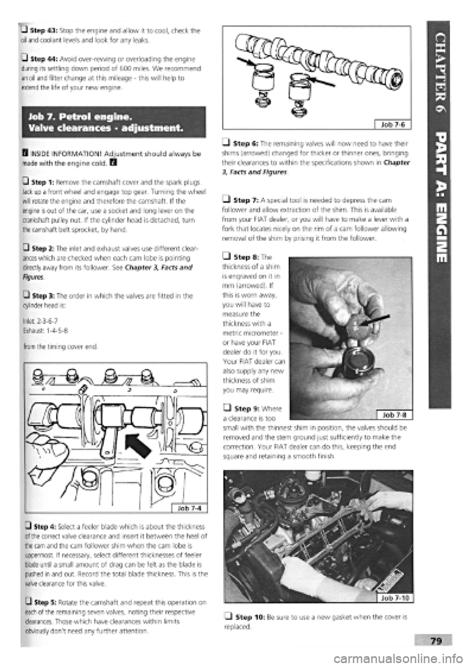
G Step 3: The order in which the valves are fitted in the
cylinder head is:
Inlet: 2-3-6-7
Exhaust: 1-4-5-8
from
the timing cover end.
G Step 4: Select a feeler blade which is about the thickness
of the
correct valve clearance and insert it between the heel of
the cam
and the cam follower shim when the cam lobe is
uppermost. If necessary, select different thicknesses of feeler
blade until a small amount of drag can be felt as the blade is
pushed in and out. Record the total blade thickness. This is the
valve clearance for this valve.
G Step 5: Rotate the camshaft and repeat this operation on
each
of the remaining seven valves, noting their respective
clearances. Those which have clearances within limits
obviously don't need any further attention.
Q Step 6: The remaining valves will now need to have their
shims (arrowed) changed for thicker or thinner ones, bringing
their clearances to within the specifications shown in Chapter
3, Facts and Figures
Ll Step 7: A special tool is needed to depress the cam
follower and allow extraction of the shim. This is available
from your FIAT dealer, or you will have to make a lever with a
fork that locates nicely on the rim of a cam follower allowing
removal of the shim by prising it from the follower.
• Step 8: The
thickness of a shim
is engraved on it in
mm (arrowed). If
this is worn away,
you will have to
measure the
thickness with a
metric micrometer
-
or have your FIAT
dealer do it for you.
Your FIAT dealer can
also supply any new
thickness of shim
you may require.
• Step 9: Where
a clearance is too
small with the thinnest shim in position, the valves should be
removed and the stem ground just sufficiently to make the
correction. Your FIAT dealer can do this, keeping the end
square and retaining a smooth finish.
fjfefe^ | Job 7-10
Q Step 10: Be sure to use a new gasket when the cover is
replaced.
Page 78 of 171

Q Step 23: Undo the mounting bolts, making sure the
power unit is supported safely as you take the last bolts out.
• Step 24: Lower the power unit to the ground and pull
clear.
Job 9. Petrol engine/transmission
- refitting.
Q INSIDE INFORMATION! The power unit can be refitted
by simply reversing the order of the operations for
removal as set out in the previous job. However, the
following points should receive your attention as the
work progresses. H
• Step 1: Refer to Chapter
3,
Facts and Figures for the
torque settings when refitting the various components.
• Step 2: If you don't have the FIAT too! (arrowed) to fit
the special Oetiker bands on the drive-shaft boots, use
woodworker's pincers, or fit new jubilee clips and screw them
reasonably tight.
• Step 3: Check the condition of all hoses and clips and
replace them if suspect.
• Step 4: Make sure all the electrical connections are
correctly made and are sound.
Q Step 5: Make sure the engine and gearbox have the
correct grades and quantities of oil. See Chapter
3,
Facts
and
Figures.
Q Step 6: Check that the cooling system has the correct
coolant mixture. See Chapter
3,
Facts and Figures.
• Step 7: Make a final check that nothing has been left un-
connected before starting up.
• Step 8: Run the engine up to working temperature and
then switch off. Check for leaks and re-check the fluid levels
when cold.
Page 86 of 171
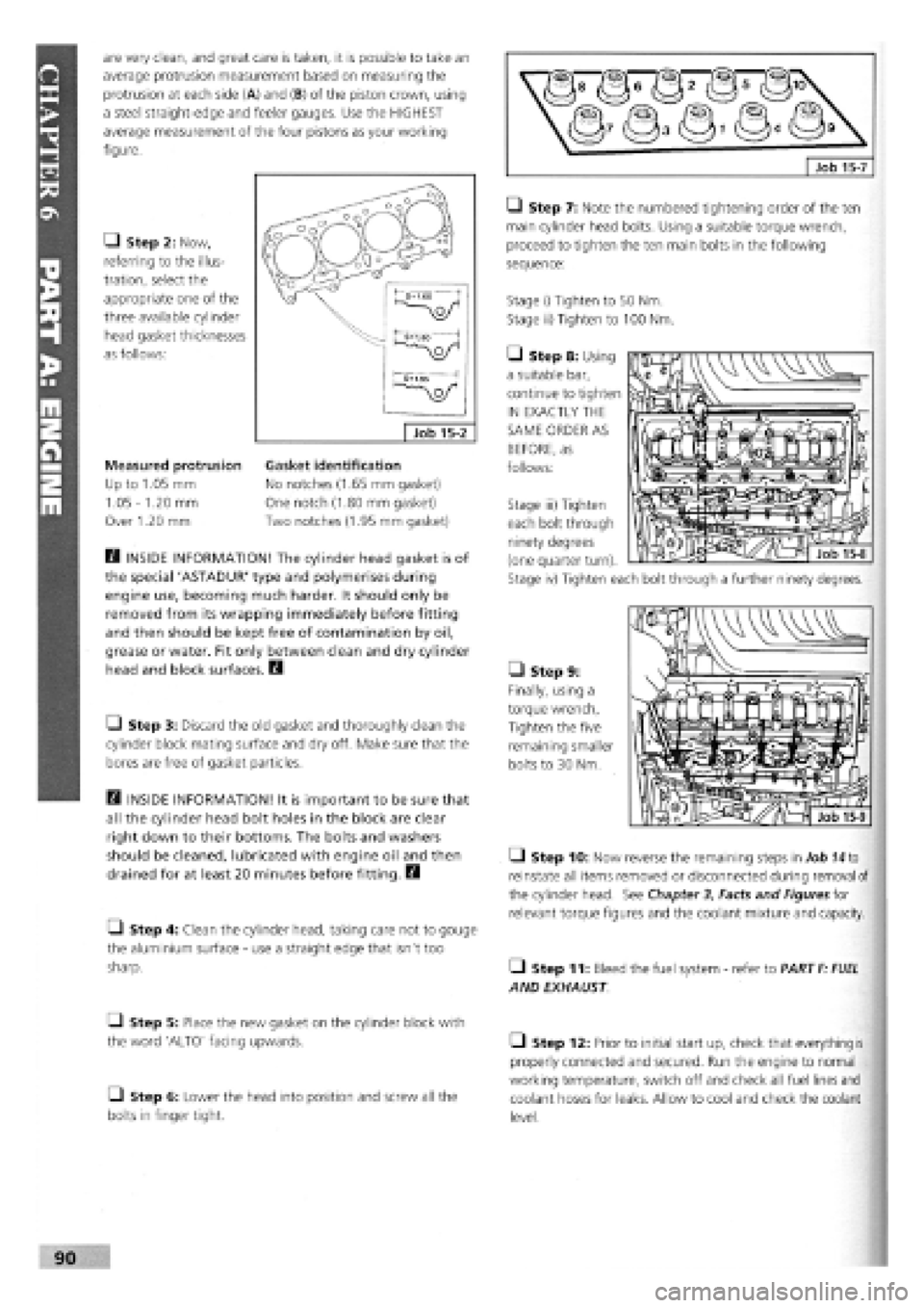
are very clean, and great care is taken, it is possible to take an
average protrusion measurement based on measuring the
protrusion at each side (A) and (B) of the piston crown, using
a steel straight-edge and feeler gauges. Use the HIGHEST
average measurement of the four pistons as your working
figure.
Q Step 2: Now,
referring to the illus-
tration, select the
appropriate one of the
three available cylinder
head gasket thicknesses
as follows:
Measured protrusion
Up to 1.05 mm
1.05
-
1.20 mm
Over 1.20 mm
B INSIDE INFORMATION! The cylinder head gasket is of
the special 'ASTADUR' type and polymerises during
engine use, becoming much harder. It should only be
removed from its wrapping immediately before fitting
and then should be kept free of contamination by oil,
grease or water. Fit only between clean and dry cylinder
head and block surfaces. B
• Step 3: Discard the old gasket and thoroughly clean the
cylinder block mating surface and dry off. Make sure that the
bores are free of gasket particles.
B INSIDE INFORMATION! It is important to be sure that
all the cylinder head bolt holes in the block are clear
right down to their bottoms. The bolts and washers
should be cleaned, lubricated with engine oil and then
drained for at least 20 minutes before fitting. B
• Step 4: Clean the cylinder head, taking care not to gouge
the aluminium surface
-
use a straight edge that isn't too
sharp.
Q Step 5: Place the new gasket on the cylinder block with
the word 'ALTO' facing upwards.
• Step 6: Lower the head into position and screw all the
bolts in finger tight.
LI Step 7: Note the numbered tightening order of the ten
main cylinder head bolts. Using a suitable torque wrench,
proceed to tighten the ten main bolts in the following
sequence:
Stage i) Tighten to 50 Nm.
Stage ii) Tighten to 100 Nm.
• Step 8: Using
a suitable bar,
continue to tighten
IN EXACTLY THE
SAME ORDER AS
BEFORE, as
follows:
• Step 9:
Finally, using a
torque wrench,
Tighten the five
remaining smaller
bolts to 30 Nm.
Q Step 10: Now reverse the remaining steps in Job
74
to
reinstate all items removed or disconnected during removal of
the cylinder head. See Chapter
3,
Facts and Figures for
relevant torque figures and the coolant mixture and capacity.
• Step 11: Bleed the fuel system
-
refer to PART
F: FUEL
AND EXHAUST
• Step 12: Prior to initial start up, check that everything is
properly connected and secured. Run the engine to normal
working temperature, switch off and check all fuel lines and
coolant hoses for leaks. Allow to cool and check the coolant
level.
Gasket identification
No notches (1.65 mm gasket)
One notch (1.80 mm gasket)
Two notches (1.95 mm gasket)
Stage iii) Tighten
each bolt through
ninety degrees
(one quarter turn).
Stage iv) Tighten each bolt through a further ninety degrees.
Page 89 of 171

Job 17. Diesel engine.
Valve clearances - adjustment.
D INSIDE INFORMATION! After carrying out Job 16,
valve clearance measurement and adjustment is now
needed. Both measurement and shim replacement are
carried out in the same manner as for the petrol engine
(.Job
7), so refer to this and also to Chapter 3, Facts
and Figures for specifications. B
Job 18. Diesel engine - removal.
moving parts with engine oil during assembly. See Chapter 3,
Facts
and Figures for specified tightening torques.
luei suppiy diiu leium pipe;>
at the injection pump...
• Step 9: ...and the stop
control supply cable. Also
disconnect the cable from
the injection pump hydraulic
advance control sensor and
the alternator cables.
• Step 10:
Disconnect the oil
feed and return
pipes between the
thermostatic valve
and the radiator
and tie clear.
I
This should
be read in connection with Job 8
Q INSIDE INFORMATION! • The turbo and non-turbo
diesel engines are essentially similar.
• The under-bonnet scene is in some ways different
because of the extra plumbing required when a turbo is
fitted.
• Locations and shapes of various items may differ, or
not exist at all on the non-turbo unit.
• As most complexity is found with the turbo engine,
I
the
following illustrations are mainly of this version.
• The power units are removed from under the car,
therefore make sure you can raise the car enough to
achieve this. Support the car firmly and safely on axle
stands. D
Q Step 1: Disconnect the negative lead from the battery
and drain
the cooling system. Q Step 2: Remove the bonnet lid.
• Step 3: Drain the transmission oil.
Q Step 4: Disconnect and remove all pipes and hoses.
Q Step 5: Undo all electrical connection and label them
with masking
tape. Write matching numbers on each male
and female
connection to assist reconnection, later.
Q Step 6: Disconnect the power steering pump pipes
(where fitted),
catching any spilt fluid and tie them clear. See
Job 14.
• Step 7: Part the
connection for the
electronic
speedometer
magnetic impulse
generator
(when fitted).
Q Step 11: Disconnect the clutch cable, adjacent earth lead
and reversing light switch other cable connection from the top
of the gearbox.
• Step 12: Disconnect the leads from the oil pressure
warning light from the oil filter mounting, and the oil level
warning light switch.
• Step 13: From under the car, remove the exhaust front
section from the manifold and from its support brackets.
O Step 14: Remove the front road wheels and the access
panel from each wheel housing.
• Step 15: Remove the brake pad wear sensor cables,
when fitted.
Q Step 16A: On the turbo version, undo the six 'Allen'
screws securing the inboard end of each drive-shaft. Undo the
two pinch bolts that fix each stub axle to the suspension struts
and pull them clear. Ease the drive-shafts clear of the trans-
mission casing
-
take care
not to
damage the
protective
boots.