1988 FIAT TEMPRA height adjustment
[x] Cancel search: height adjustmentPage 10 of 171

• 9. DOOR MIRROR ADJUSTMENT
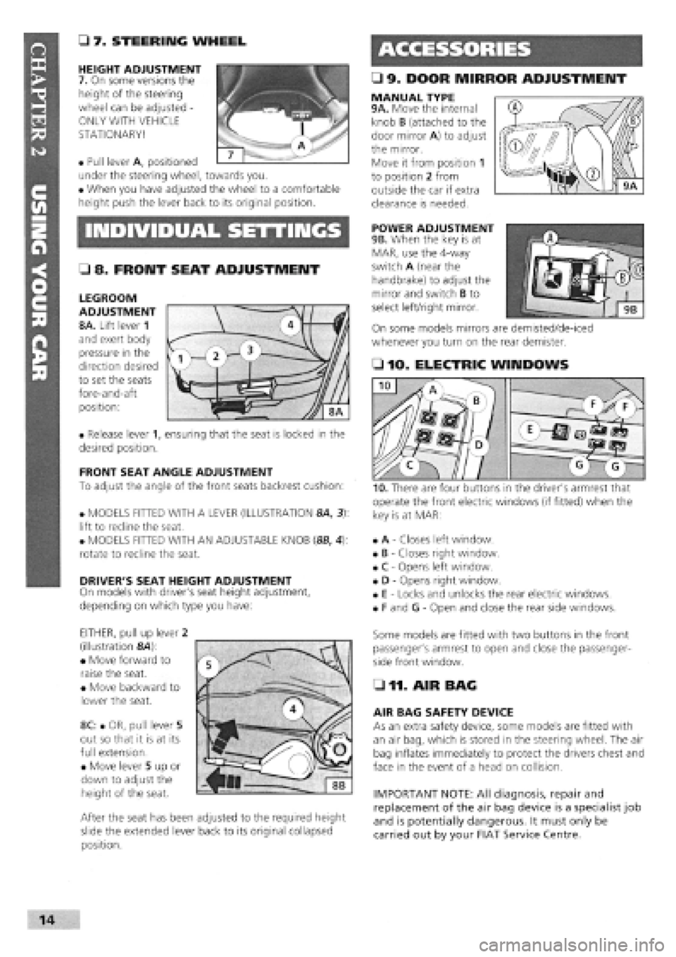
• 7. STEERING WHEEL
HEIGHT ADJUSTMENT
7. On some versions the
height of the steering
wheel can be adjusted -
ONLY WITH VEHICLE
STATIONARY!
• Pull lever A, positioned
under the steering wheel, towards you.
• When you have adjusted the wheel to a comfortable
height push the lever back to its original position.
MANUAL TYPE 9A. Move the internal
knob B (attached to the
door mirror A) to adjust
the mirror.
Move it from position 1
to position 2 from
outside the car if extra
clearance is needed.
INDIVIDUAL SETTINGS POWER ADJUSTMENT
9B. When the key is at
MAR, use the 4-way
switch A (near the
handbrake) to adjust the
mirror and switch B to
select left/right mirror.
On some models mirrors are demisted/de-iced
whenever you turn on the rear demister.
• 8. FRONT SEAT ADJUSTMENT
LEGROOM
ADJUSTMENT
8A. Lift lever 1
and exert body
pressure in the
direction desired
to set the seats
fore-and-aft
position:
• Release lever 1, ensuring that the seat is locked in the
desired position.
FRONT SEAT ANGLE ADJUSTMENT
To adjust the angle of the front seats backrest cushion:
• MODELS FITTED WITH A LEVER (ILLUSTRATION 8A, 3):
lift to recline the seat.
• MODELS FITTED WITH AN ADJUSTABLE KNOB (8B, 4):
rotate to recline the seat.
DRIVER'S SEAT HEIGHT ADJUSTMENT
On models with driver's seat height adjustment,
depending on which type you have:
EITHER, pull up lever 2
(illustration &4):
• Move forward to
raise the seat.
• Move backward to
lower the seat.
8C: • OR, pull lever 5
out so that it is at its
full extension.
• Move lever 5 up or
down to adjust the
height of the seat.
After the seat has been adjusted to the required height
slide the extended lever back to its original collapsed
position.
• 10. ELECTRIC WINDOWS
operate the front electric windows (if fitted) when the
key is at MAR:
• A
-
Closes left window.
• B
-
Closes right window.
• C
-
Opens left window.
• D
-
Opens right window.
• E
-
Locks and unlocks the rear electric windows.
• F and G
-
Open and close the rear side windows.
Some models are fitted with two buttons in the front
passenger's armrest to open and close the passenger-
side front window.
• 11. AIR BAG
AIR BAG SAFETY DEVICE
As an extra safety device, some models are fitted with
an air bag, which is stored in the steering wheel. The air
bag inflates immediately to protect the drivers chest and
face in the event of a head on collision.
IMPORTANT NOTE: All diagnosis, repair and
replacement of the air bag device is a specialist job
and is potentially dangerous. It must only be
carried out by your FIAT Service Centre.
I
Page 15 of 171

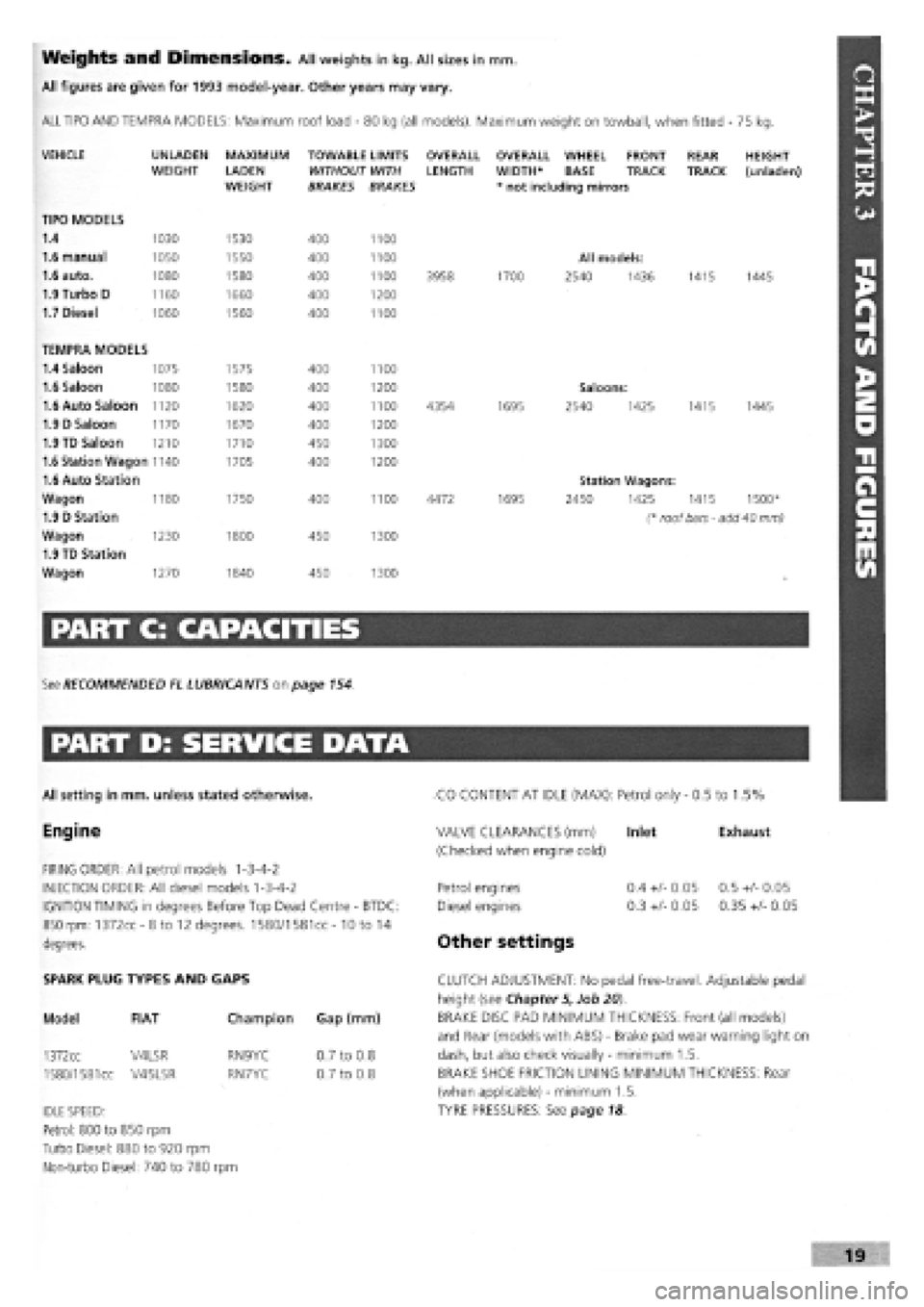
Weights and Dimensions. All weights in kg. All sizes in mm.
All figures are given for 1993 model-year. Other years may vary.
ALL TIPO AND TEMPRA MODELS: Maximum roof load
-
80 kg (all models). Maximum weight on towball, when fitted - 75 kg.
VEHICLE
TIPO MODELS
1.4
1.6 manual
1.6 auto.
1.9 Turbo D
1.7 Diesel
UNLADEN WEIGHT
1030
1050
1080
1160
1060
MAXIMUM
LADEN WEIGHT
1530
1550
1580
1660
1560
TOWABLE LIMITS WITHOUT WITH BRAKES BRAKES
400
400
400
400
400
1100
1100
1100
1200
1100
OVERALL LENGTH
3958
OVERALL WHEEL FRONT WIDTH* BASE TRACK * not including mirrors
1700
All models:
2540 1436
REAR TRACK
1415
HEIGHT (unladen)
1445
TEMPRA MODELS
1.4 Saloon 1075 1575 400 1100
1.6 Saloon 1080 1580 400 1200 Saloons:
1.6 Auto Saloon 1120 1620 400 1100 4354 1695 2540 1425 1415 1445
1.9 D Saloon 1170 1670 400 1200
1.9 TD Saloon 1210 1710 450 1300
1.6 Station Wagon 1140 1705 400 1200
1.6 Auto Station Station Wagons:
Wagon 1180 1750 400 1100 4472 1695 2450 1425 1415 1500*
1.9 D Station (* roof bars - add 40 mm)
Wagon 1230 1800 450 1300
1.9 TD Station
Wagon 1270 1840 450 1300
PART C: CAPACITIES
See RECOMMENDED EL LUBRICANTS on page 154.
PART D: SERVICE DATA
All setting in mm. unless stated otherwise.
Engine
FIRING ORDER: All petrol models 1-3-4-2
INJECTION ORDER: All diesel models 1-3-4-2
IGNITION TIMING in degrees Before Top Dead Centre
-
BTDC:
850 rpm: 1372cc-8to 12 degrees. 1580/1581cc- 10 to 14
degrees.
CO CONTENT AT IDLE (MAX): Petrol only
-
0.5 to 1.5%
Exhaust VALVE CLEARANCES (mm) Inlet
(Checked when engine cold)
Petrol engines
Diesel engines
Other settings
0.4
+/-
0.05
0.3
+/-
0.05
0.5
+/-
0.05
0.35
+/-
0.05
SPARK PLUG TYPES AND GAPS
Model FIAT
1372cc V4LSR
1580/1581
cc V45LSR
Champion Gap (mm)
RN9YC
RN7YC
IDLE SPEED:
Petrol: 800 to 850 rpm
Turbo Diesel: 880 to 920 rpm
Non-turbo Diesel: 740 to 780 rpm
0.7 to 0.8
0.7 to 0.8
CLUTCH ADJUSTMENT: No pedal free-travel. Adjustable pedal
height (see Chapter 5, Job 20).
BRAKE DISC PAD MINIMUM THICKNESS: Front (all models)
and Rear (models with ABS)
-
Brake pad wear warning light on
dash, but also check visually
-
minimum 1.5.
BRAKE SHOE FRICTION LINING MINIMUM THICKNESS: Rear
(when applicable)
-
minimum 1.5.
TYRE PRESSURES: See page 18
Page 58 of 171

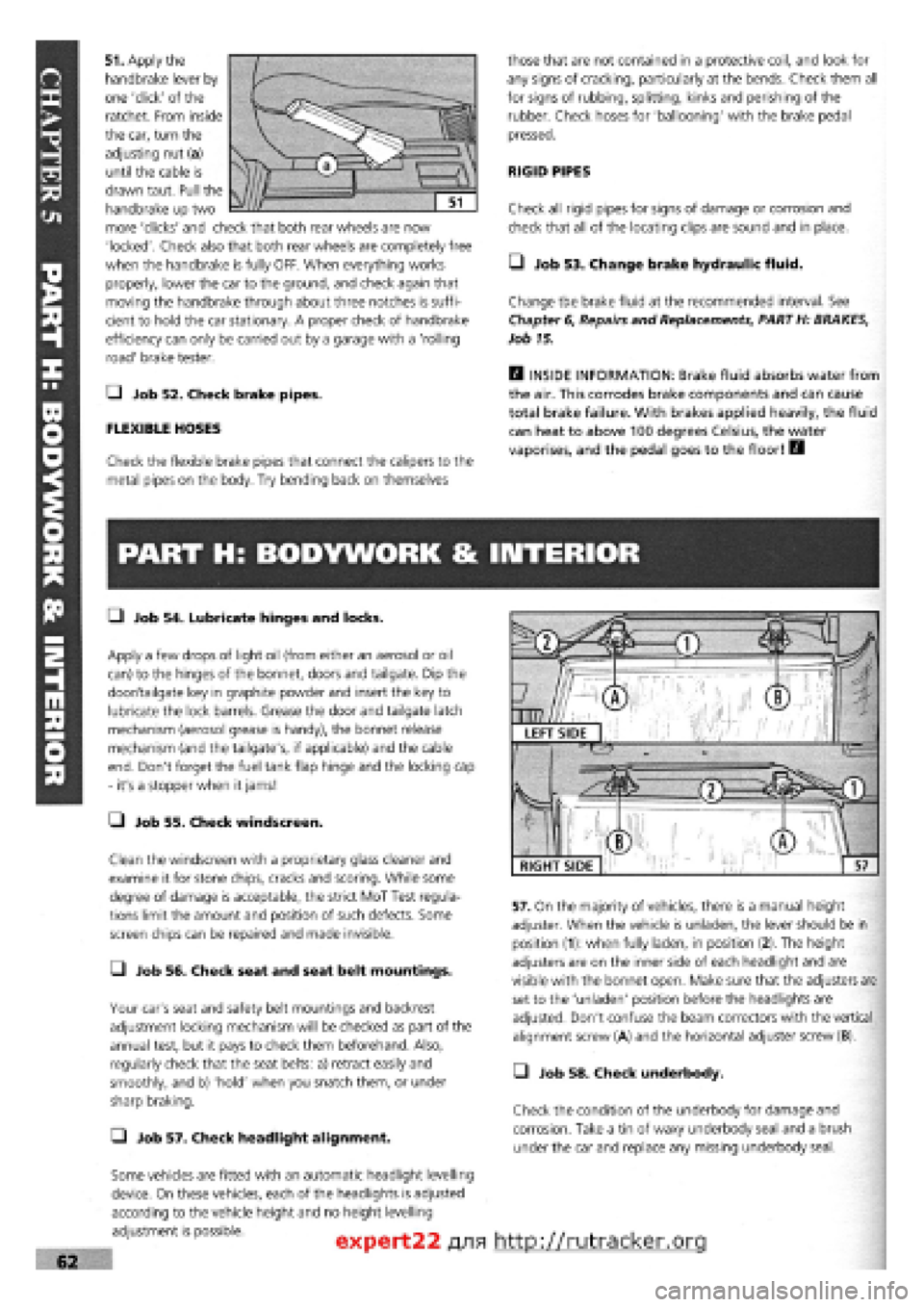
51. Apply the
handbrake lever by
one 'click' of the
ratchet. From inside
the car, turn the
adjusting nut (a)
until the cable is
drawn taut. Pull the
handbrake up two
more 'clicks' and check that both rear wheels are now
'locked'. Check also that both rear wheels are completely free
when the handbrake is fully OFF. When everything works
properly, lower the car to the ground, and check again that
moving the handbrake through about three notches is suffi-
cient to hold the car stationary. A proper check of handbrake
efficiency can only be carried out by a garage with a 'rolling
road' brake tester.
Q Job 52. Check brake pipes.
FLEXIBLE HOSES
Check the flexible brake pipes that connect the calipers to the
metal pipes on the body. Try bending back on themselves
those that are not contained in a protective coil, and look for
any signs of cracking, particularly at the bends. Check them all
for signs of rubbing, splitting, kinks and perishing of the
rubber. Check hoses for 'ballooning' with the brake pedal
pressed.
RIGID PIPES
Check all rigid pipes for signs of damage or corrosion and
check that all of the locating clips are sound and in place.
• Job 53. Change brake hydraulic fluid.
Change the brake fluid at the recommended interval. See
Chapter
6,
Repairs and Replacements, PART H: BRAKES,
Job 15.
H INSIDE INFORMATION: Brake fluid absorbs water from
the air. This corrodes brake components and can cause
total brake failure. With brakes applied heavily, the fluid
can heat to above 100 degrees Celsius, the water
vaporises, and the pedal goes to the floor! B
PART H: BODYWORK & INTERIOR
• Job 54. Lubricate hinges and locks.
Apply a few drops of light oil (from either an aerosol or oil
can) to the hinges of the bonnet, doors and tailgate. Dip the
door/tailgate key in graphite powder and insert the key to
lubricate the lock barrels. Grease the door and tailgate latch
mechanism (aerosol grease is handy), the bonnet release
mechanism (and the tailgate's, if applicable) and the cable
end. Don't forget the fuel tank flap hinge and the locking cap
- it's a stopper when it jams!
• Job 55. Check windscreen.
Clean the windscreen with a proprietary glass cleaner and
examine it for stone chips, cracks and scoring. While some
degree of damage is acceptable, the strict MoT Test regula-
tions limit the amount and position of such defects. Some
screen chips can be repaired and made invisible.
• Job 56. Check seat and seat belt mountings.
Your car's seat and safety belt mountings and backrest
adjustment locking mechanism will be checked as part of the
annual test, but it pays to check them beforehand. Also,
regularly check that the seat belts: a) retract easily and
smoothly, and b) 'hold' when you snatch them, or under
sharp braking.
Q Job 57. Check headlight alignment.
Some vehicles are fitted with an automatic headlight levelling
device. On these vehicles, each of the headlights is adjusted
according to the vehicle height and no height levelling
adjustment is possible.
57. On the majority of vehicles, there is a manual height
adjuster. When the vehicle is unladen, the lever should be in
position (1): when fully laden, in position (2). The height
adjusters are on the inner side of each headlight and are
visible with the bonnet open. Make sure that the adjusters are
set to the 'unladen' position before the headlights are
adjusted. Don't confuse the beam correctors with the vertical
alignment screw (A) and the horizontal adjuster screw (B).
• Job 58. Check underbody.
Check the condition of the underbody for damage and
corrosion. Take a tin of waxy underbody seal and a brush
under the car and replace any missing underbody seal.
expert22 fl/ia http://rutracker.org
RIGHT SIDE
Page 139 of 171

PART I: BODY AMD INTERIOR
PART 1: Contents
Job 1. Bonnet
-
removal and refitting. Job 8. Tempra boot lid locking mechanism
-
removal and
Job 2. Bonnet locking mechanism
-
replacement and refitting.
adjustment. Job 9. Front bumper and grille
-
removal and refitting.
Job 3. Radiator grille
-
removal and refitting. Job 10. Rear bumper
-
removal and refitting.
Job 4. Tipo/Tempra tailgate
-
removal and refitting. Job 11. Door trim panel
-
removal and refitting.
Job 5. Tipo tailgate locking mechanism
-
removal and Job 12. Door component
-
removal and replacement
refitting. Job 13. Door removal, replacement and adjustment.
Job 6. Tempra estate tailgate locking mechanism
-
removal Job 14. Door mirror
-
replacement.
and refitting. Job 15. Sun roof
-
removal and refitting.
Job 7. Tempra boot lid
-
removal and refitting. Job 16. Front seats
-
removal and refitting.
-Job 17. Rear seats
-
removal and refitting.
Job 1. Bonnet - removal and
refitting.
Job 2. Bonnet locking mechanism
- replacement and adjustment.
• Step 1: Note the bonnet hinges, support and stops.
G Step 2: Use the prop and hold the bonnet open. Outline
the hinge positions on the bonnet with masking tape for
accurate refitment.
G Step 3: Ask an assistant to support the bonnet. Undo the
two hinge fixing bolts. Carefully lift the bonnet clear.
if refitting the bonnet, put a
piece of cloth under each
rear corner to protect the bodywork.
• Step 1: This drawing shows left and right hand drive
layouts. Select which is right for your car.
• Step 2: The two screws (illustration Job 2-3 arrowed)
used to fix the locking pin/safety catch assembly to the bonnet
are also used for fore and aft adjustment. This is best done a
little at a time until smooth operation is achieved.
• Step 3: Height
adjustment (levelling with
the wings) is achieved by
screwing the bump stops
(inset, arrowed) up or
down. Then slacken the
G Step 5: When refitting, tighten the bolts just enough to
grip the hinges, then carefully lower the bonnet to check for
correct alignment all round
-
equal gapping.
When the alignment is satisfactory, tighten the bolts to their
correct torque, See Chapter 3, Facts and Figures
[G Step 4: To remove the lock/striker assembly, separate the
cable eyelet from the operating lever hook, see illustration Job
2-1, parts 13 and 14
1 - lock/striker assembly, front panel 2 - locking pin/safety catch, bonnet 3 - release lever. (Also fitted other side, some R/H drive cars) 4 - cable, L/H drive 5 - cable, R/H drive
and secondary cable, R/H drive 7 - screw 8
-
washer 9 - bolt 10 - bolt
11 - cable clip 12 - cable fixing screw 13 - cable eyelet 14 - operating lever hook Job 2-1
locking nut (hidden
behind the locking pin
spring) and screw the
locking pin up or down
until the bonnet will shut
when dropped from 30 cm height and then have no
movement on the lock. Don't forget to tighten the locknut.