1988 FIAT TEMPRA fuel pump
[x] Cancel search: fuel pumpPage 74 of 171

• Step 30: Fit
the crankshaft
pulley and
tighten. See
Chapter 3,
Facts and
Figures.
• Step 31: Fit the
water pump and
distribution pipe.
• Step 32A: Refit the
flywheel. Do not unbolt the
TDC sensor (1) from the oil seal
housing at its mounting plate
bolts
(2)
unless it is essential to
do so.
• Step 32B: If
the sensor
mounting plate has
to be disturbed, you
will need the FIAT
special tool illus-
trated here (inset) in
order to reposition it
correctly. Position
the timing mark on
the crankshaft
pulley with the zero
degrees mark on the outer timing belt cover (and double
check that the timing mark on the flywheel
-
rubber bung
removed
-
is aligned at zero degrees).
With the bracket fitted to the oil seal housing, fit the FIAT
special tool onto the bracket in place of the sensor with a slot
in the tool fitting exactly over the TDC pin on the flywheel.
When everything is lined up, position the bracket accurately
and tighten the bolts. Remove the tool and refit the sensor.
IMPORTANT NOTE: During assembly, a shear-bolt will
have been fitted to prevent accidental movement of the
bracket. If you need to undo it, you will need to drill it
out and you should replace it with a new one obtained
from your FIAT dealership.
• Step 33: Refit the clutch. See PARTB: TRANSMISSION,
Job 4.
Q Step 34: Refit the fuel pump and pushrod using new
gaskets on both sides of the spacer block, 0.3 mm thick
between the spacer and the engine and 0.7 mm between the
spacer and the pump. See PART F: FUEL AND EXHAUST for
information on setting the pump position.
• Step 35:
Lubricate the sealing
ring and screw on a
new oil filter.
• Step 36:
Before refitting the
distributor, (see
PART D: IGNITION)
refit, if necessary,
the oil pump drive
gear.
• Step 37: Refit
all remaining
auxiliary compo-
nents (including the
oil vapour recovery
device, shown here),
using new gaskets
as necessary and
referring to
Chapter
3,
Facts
and Figures for the
torque settings.
Q Step 38: Reconnect the engine to the transmission. See
Job 11.
Q Step 39: Refit the complete unit to the car. See Job
9.
• Step 40: fl INSIDE INFORMATION! Before fitting the
spark plugs and with a fully charged battery, turn the
engine on the starter until the oil warning light goes
out. This primes the lubrication system and gives more
immediate oil pressure on initial start up after overhaul-
a critical time in the life of an engine. B
• Step 41: Fit the spark plugs and start the engine
-
this
might take a few seconds more than normal on the initial start
up.
• Step 42: Allow the engine to warm up on fast idle
until
it
reaches working temperature and then slow it down to its
normal speed (if adjustable
-
see PART F: FUEL AND
EXHAUST)
Page 76 of 171

Job 8. Petrol engine/transmission
- removal.
IMPORTANT NOTE: See PARTB: TRANSMISSION for
gearbox removal by itself.
H INSIDE INFORMATION! The complete engine/trans-
mission unit is removed and replaced from under the car
- and this applies to all types. Make sure you can raise
the front of the car high enough (and support it safely
and securely!) to allow the power unit to be pulled clear
from underneath, before starting work! 13
• Step 1: Remove the bonnet
-
see PARTI: BODY AND
INTERIOR, Job 1.
• Step 5:
Disconnect the
carburettor or
injector fuel lines,
choke and throttle
cables and hoses and
electrical connections
(arrowed).
Q Step 6: Disconnect the starter motor cables, HT leads,
fuel pump lines, sensors and electrical connectors arrowed.
Job
8-7
• Step 2: Disconnect the battery earth lead.
• Step 3: Drain the cooling system and the engine oil.
Disconnect all hoses shown.
• Step 7: Disconnect the clutch cable (3) or clutch slave
cylinder, if hydraulic, the earth cable (2) and the reversing
lights switch cable
(1)
from the top of the gearbox.
• Step 8: Disconnect the alternator cables.
Q Step 9: Slacken the front wheel bolts, raise the car and
support securely on axle stands. Remove the wheels.
• Step 10: Drain
the gearbox oil.
• Step 4:
Remove the air
filter-to-engine
connections
-
earlier type illus-
trated. (There are
some hose
connections
underneath on
the later type,
mounted on top
of the engine.) Disconnect the electrical connection and all
other hoses from the filter housing.
• Step 11:
Remove the buttons
(gearbox side,
arrowed) fixing the
dust shield to the
wheel arch on each
side.
Page 82 of 171

PART A
-
ENGINES PRIOR TO ENGINE NO. 1723291 • Step A15: Ease the timing belt off the sprockets.
Gl Step A10: Use a spanner on the crankshaft bolt (a) to
turn the engine until the timing marks on the crankshaft,
camshaft and injection pump sprockets align with their
respective reference marks. Align the crankshaft sprocket with
the notch on the front cover (b). Align the camshaft sprocket
with the hole in the timing belt cover (c). Align the injection
pump sprocket with the reference on the timing belt rear
guard (d).
• Step A11: Use
the FIAT flywheel
lock, part no.
1860766000 (or
construct your own
tool) to stop the
crankshaft from
turning.
• Step A12:
Remove the
alternator belt
pulley/damper.
• Step A13:
Using FIAT tool no.
1842128000 (see illustration Job
13-A10,
parte), lock the
injection pump sprocket to prevent it turning.
• Step A14: Slacken the belt tensioner nut (see illustration
Job
13-A10,
part f), move the tensioner away from the belt
and temporarily lock it in position.
• Step A16: Fit the new belt, first making sure that all of
the timing marks still align.
• Step A17: If you do not have access to the correct FIAT
tensioning tool, release the locknut, push the tensioner firmly
into the belt and lock it up by tightening its bolt.
If you do have the FIAT special tool (a weighted bar), attach it
to the tensioner, which will move to the position of correct
tension. Lock the tensioner bolt. Remove the special tool
locking the injection pump sprocket.
E3 INSIDE INFORMATION: If you can't put enough
pressure on the tensioner with your fingers, carefully use
a long screwdriver as a lever. Alternatively, push a pair of
bolts into the two holes in the tensioner and lever
between them to turn the tensioner. E9
Q Step A18: Rotate the engine through two revolutions. If
the belt is correctly tensioned you should just be able to twist
it through a quarter-turn when gripping it between thumb
and finger in the centre of its longest run between sprockets.
Adjust as necessary.
Q Step A19: Refit the remaining parts in the reverse order,
then check the injection timing (see Chapter
5,
Servicing
Your Car, Job
39)
PART B
-
ENGINES FROM ENGINE NO. 1723291-ON
Job 13-B10
Q Step B10: Turn the crankshaft in its normal direction of
rotation until the marks on the crankshaft sprocket (a) and
fuel injection pump sprocket (b) line up with the fixed marks
on the engine. This will place cylinder No. 1 at Top Dead
Centre TDC and set the camshaft for the power stroke of the
same cylinder. Lock the flywheel (see Step A11) and remove
the alternator belt pulley (see Step A12).
IMPORTANT NOTE: The hole for fixing the camshaft
sprocket (c) has a fine-adjustment slot, so it is possible
that the mark on the sprocket may not line up exactly
with the mark on the cover.
Page 83 of 171

Q Step B11: Undo the belt tensioner nut (see illustration
Job 13-B10, part d), then remove the timing belt.
Q Step B12: Undo the nuts securing the brake vacuum
pump to the cylinder head (see illustration Job
16-1),
and
remove it.
• Step B13: Fit FIAT tool no. 1860932000 (for setting
camshaft timing) to the vacuum pump end of the camshaft,
matching the camshaft groove (1) with the lug (2) on the tool
Secure
the tool to the cylinder head, positioning the centring
dowel
(3) as shown. The dowel must be perfectly centred on
the tool,
and if it isn't, you should adjust the hexagonal bolt
(4) with
a spanner, and centre it with tiny movements.
• Step B14:
Remove
the bolt
(arrowed) which
secures
the front
cover
to the engine
block,
then fit the
timing belt on the
crankshaft sprocket.
• Step B16:
Lock the injection
pump sprocket (see
StepA13). Now,
using FIAT tool no.
1860831000,
slacken the bolt
securing the
camshaft sprocket.
• Step B17: Continue fitting the timing belt in the
following sequence: crankshaft sprocket, fixed tensioner,
injection pump sprocket, timing sprocket, belt tensioner... and
check that the mark on the injection pump lines up with the
fixed mark on the rear cover.
• Step B18: Use the timing belt tensioner to correctly
tension the belt.
B INSIDE INFORMATION: If you do not have the correct
tensioning tool, follow Steps A16 and A17. B
• Step B19: Tighten the camshaft sprocket bolt to the 1
specified torque (see Chapter
3,
Facts and Figures).
Q Step B20: Turn the crankshaft by two revolutions
(clockwise), tighten the belt tensioner to the specified torque
(see Chapter
3,
Facts and Figures) and remove the
tensioning tools. If the belt is correctly tensioned you should
just be able to twist it through a quarter-turn when gripping it
between thumb and finger in the centre of its longest run
between sprockets. Adjust as necessary.
O Step B21: Refit the remaining components in the reverse
order of removal, then check the injection timing. See
Chapter
5,
Servicing Your Car, Job 25.
Job 14. Diesel engine.
Cylinder head - removal.
• Disconnecting the high pressure pipes on a diesel
injection system can be dangerous!
• Read the Safety First! information at the start of
PART F: FUEL AND EXHAUST SYSTEMS before
starting work.
Q Step 1: Refer to Job
13
and remove the timing belt.
• Step 2: Drain the cooling system and disconnect the air
pipes from the inlet manifold.
Q Step 3: Disconnect
and remove the oil vapour
pipes from the cylinder
block device.
Job 13-B13
• Step B15: Fit
FIAT tool
No.
1860933000 for
precise
determination
of TDC
on cylinder
No. 1. The
tool must
be secured
firmly by
two bolts
to the
crankshaft sprocket,
and by
another bolt
to the
crankshaft front cover (where the bolt was previously
removed in Step B14).
Page 84 of 171
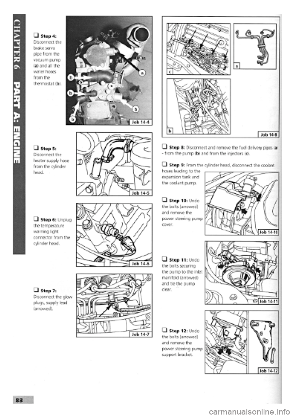
• Step 4:
Disconnect the
brake servo
pipe from the
vacuum pump
(a) and all the
water hoses
from the
thermostat (b).
• Step 5:
Disconnect the
heater supply hose
from the cylinder
head.
• Step 6: Unplug
the temperature
warning light
connector from the
cylinder head.
• Step 7:
Disconnect the glow
plugs, supply lead
(arrowed).
Q Step 8: Disconnect and remove the fuel delivery pipes (a)
- from the pump (b) and from the injectors (c).
• Step 9: From the
hoses leading to the
expansion tank and
the coolant pump.
• Step 10: Undo
the bolts (arrowed)
and remove the
power steering pump
cover.
• Step 11: Undo
the bolts securing
the pump to the inlet
manifold (arrowed)
and tie the pump
clear.
• Step 12: Undo
the bolts (arrowed)
and remove the
power steering pump
support bracket.
88
cylinder head, disconnect the coolant
Job 14-10
Job 14-12
Job 14-11
Page 87 of 171
Job 16. Diesel engine.
Cylinder head - overhaul.
Job 16-1
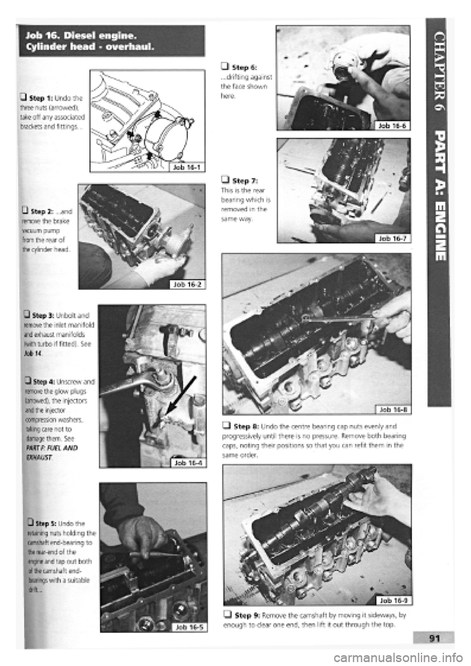
• Step 1: Undo the
three nuts (arrowed),
take off any associated
brackets and fittings...
• Step 2: ...and
remove the brake
vacuum pump
from
the rear of
the
cylinder head.
• Step 3: Unbolt and
remove
the inlet manifold
and
exhaust manifolds
(with
turbo if fitted). See
Job 14.
Q Step 4: Unscrew and
remove
the glow plugs
(arrowed), the injectors
and the
injector
compression washers,
taking
care not to
damage them.
See
PART F:
FUEL AND
EXHAUST.
• Step 5: Undo the
retaining nuts holding the
camshaft end-bearing to
the rear-end
of the
engine and
tap out both
of the
camshaft end-
bearings with
a suitable
drift...
• Step 8: Undo the centre bearing cap nuts evenly and
progressively until there is no pressure. Remove both bearing
caps, noting their positions so that you can refit them in the
same order.
• Step 9: Remove the camshaft by moving it sideways, by
enough to clear one end, then lift it out through the top.
• Step 6:
...drifting against
the face shown
here.
• Step 7:
This is the rear
bearing which is
removed in the
same way.
Page 91 of 171
Q Step 2: Before starting the engine, make sure all your
electrical connections are sound and your fuel, oil and coolant
connections are correct and secure.
Q Step 3: Run the engine to working temperature and then
allow to cool. Re-check all fluid levels.
Job 20. Diesel engine.
Mountings - replacement.
See
Job
12
and Job
18,
Step 20
Job 21. Diesel engine/
transmission (removed from car)
- separation.
Q Step 1: Remove the starter motor.
• Step 2: On the turbo version, undo the flange bolts see
Job
18,
Step 16A and withdraw the drive-shaft extension, if
still
fitted.
Q Step 3: Unbolt and remove the rear engine plate and the
gearbox, being careful to support the gearbox weight as it is
withdrawn.
Job 22. Diesel engine/
transmission (removed from car)
- reconnection.
Q Step 1: Before proceeding, check the condition of the
clutch and
its release mechanism. Make sure the driven plate
is
properly centred on the flywheel
-
see PART B: TRANS-
MISSION.
Q Step 2: Now reverse the order of separation, but be
careful when
engaging the gearbox input shaft with the
clutch
driven plate that you don't 'hang' its weight on the
splines.
Also,
see
Job 11.
Job 23. Diesel engine -
dismantling.
This Job should
be read in conjunction with Job 5 The
engines are
broadly similar although the information given in
this Job takes
priority for diesel engines. It is MOST
IMPORTANT that you read the FACT FILE on page 84.
SAFETY FIRST!
•
The inside
of diesel engines are particularly filthy
places!
•
Old diesel
oil
is
carcinogenic!
•
Wear suitable
impervious gloves!
I
• Step 1: Remove the timing belt and cylinder head. See
Jobs
13
and 14.
Q Step 2: Remove the alternator, water pump and
thermostat housing distribution pipe.
• Step 3: Remove the crankshaft timing belt sprocket.
Q INSIDE INFORMATION! Note that the bolt securing
the crankshaft sprocket has a left-hand thread and must
be undone clockwise. D
• Step 4: Unbolt the timing belt tensioner and idler pulleys.
• Step 5: Remove the injection pump sprocket.
Q INSIDE INFORMATION! You will need two FIAT tools
for this operation. One (No. 1860473000) is to prevent
the sprocket from turning when undoing the nut, and
the other (extractor No. 1842128000) to pull the sprocket
from the injection pump shaft. Alternatively it may be
possible to improvise a means of preventing sprocket
rotation, and a suitable three-leg puller may be carefully
used to withdraw the sprocket. Take care not to lose the
pump shaft Woodruff key. B
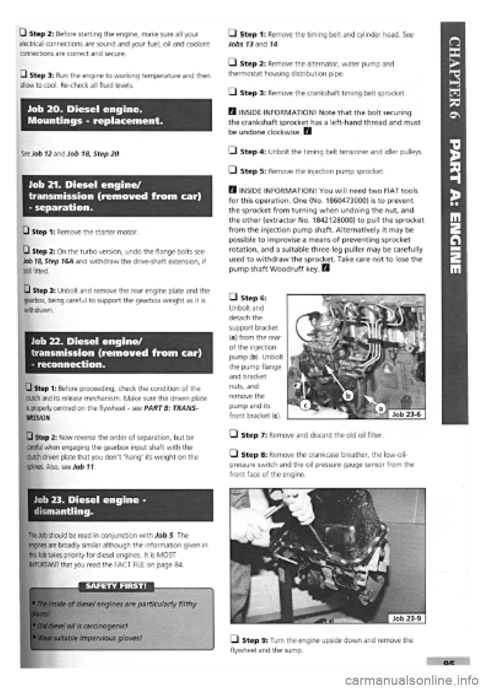
• Step 6:
Unbolt and
detach the
support bracket
(a) from the rear
of the injection
pump (b). Unbolt
the pump flange
and bracket
nuts, and
remove the
pump and its
front bracket (c).
• Step 7: Remove and discard the old oil filter.
Step 8: Remove the crankcase breather, the low-oil-
pressure switch and the oil pressure gauge sensor from the
front face of the engine.
• Step 9: Turn the engine upside down and remove the
flywheel and the sump.
Page 94 of 171

U Step 12: Fit a new seal to the front cover/oil pump
assembly, unless a new pump is being fitted, and install with a
new gasket, lightly oiling both gasket and seal. Align the cover
with the sump support plate.
PISTON CONNECTING RODS ASSEMBLIES
• Step 13:
H INSIDE
INFORMATION!
Refer to the illus-
tration and note
that the piston
should be fitted
to the connecting
rod so that when
viewed from the
timing end the
crown lift (1) is
on the right
hand/injection
pump (2) side. At
the same time,
the bore numbers
stamped on the connecting rod (3) should face left, the
opposite side. The piston pins are an interference fit in
the pistons and can be tapped into position using an
ordinary drift and secured with circlips. H
Refer to Job 6. Steps 11 to
18,
for installation procedures.
Q Step 14: Refit the oil pump pick-up and return pipes.
• Step 15: Refit the sump using a new gasket. Check that
the drain plug is tight.
• Step 16: Complete the reassembly by fitting all the
external components in the reverse order of removal. Refer to
Job
15
for cylinder head refitting.
• Step 17: Reconnect the engine to the transmission. See
Job
22
• Step 18: Refit the complete unit to the car. See Job
19
• Step 19: Bleed the fuel system. See PART F: FUEL AND
EXHAUST
Q INSIDE INFORMATION! Bleeding the fuel system
involves turning the engine on the starter. This should
allow it to gain oil pressure before 'firing up', but check
that the oil light has gone out as soon as the engine
starts. H
Q Step 20: Allow the engine to run at 'fast idle' until it
reaches working temperature and switch off. Allow it to cool
and check the oil and coolant levels and look for any leaks.
Q Step 21: Avoid over-rewing or overloading the engine
during its settling down period of 600 miles. We recommend
an oil and filter change at this mileage
-
this will help to
extend the life of your engine.
PART B: TRANSMISSION
PART B: Contents
Job 1. Transmission removal (with engine in car).
Job 2. Transmission refitting (with engine in car).
Job 3. Clutch
-
replacement.
Job 4. Clutch cable
-
replacement.
Job 5. Gear lever and linkage
-
removal and refitting.
Job 6. Kickdown cable (automatic transmission)
-
replacement.
Job 7. Kickdown cable (automatic transmission)
-
adjustment.
Job 8. Automatic gear selector control cable
-
replacement.
Job 9. Drive-shaft
-
removal and refitting.
Job 10. Drive-shaft (outer) constant velocity joint
-
replacement.
Job 11. Drive-shaft inner spider joint
-
replacement.
Job 12. Drive-shaft damper
-
replacement.
Job 13. Front hub/bearings
-
replacement.
Job 14. Hydraulic clutch components.
Job 1. Transmission removal
(with engine in car).
IMPORTANT NOTE: This operation is for cars fitted with
the 1400 and 1600cc petrol engines and non-turbo diesel
engines. For the 1930cc turbo diesel engined version the
complete power unit must be removed and then
separated. See PART A, Jobs 18, 19, 21 and 22 for the
removal of several of the ancillaries detailed here.
• Step 1:
Before
starting
work, ensure
that you can
support the
car suffi-
ciently high
off the ground for the gearbox to be removed from beneath.
Make sure that the gearbox-end of the engine is supported
from above the car, or from beneath. You may be able to
fabricate your own version of this FIAT tool (arrowed).