1988 FIAT TEMPRA brake fluid
[x] Cancel search: brake fluidPage 29 of 171

Thanks
are due to the excellent, knowledgeable and helpful staff at FIAT main dealers, Ryauto of Amblecote, in the West
Midlands for supplying vehicles and for their assistance with this chapter. In particular, thanks are due to the efficient Maurice
Hough, Service Manager, the experienced Foreman, Tony Morris, and young demon mechanic, Matthew Worsfold.
Some of the suggested inspection/replacement intervals may not correspond to those shown in the original handbook. The suggested
schedule, based on FIAT'S recommendations, takes into account the age of the vehicle and the annual MoT test in the UK.
In practice, because of the split between (mainly) 12 month/9,000 mile and 18 month/13,500 mile intervals, you will need to
service your Tipo or Tempra at most, if not every, 6 month interval.
IMPORTANT NOTE: Each service should be carried out at EITHER the recommended mileage OR the recommended time
interval, whichever comes first.
SERVICE INTERVAL CHART
SERVICE INTERVALS: KEY
A
-
Every week, or before every long journey. F
-
Every 3 years or 27,000 miles.
B
-
Every 6 months, or 4,500 miles. G
-
Every 4 years or 36,000 miles.
C - Every 12 months, or 9,000 miles. H
-
Every 6 years or 54,000 miles.
I
-
Every 63,000 miles. D - Every 18 months , or 13,500 miles.
H
-
Every 6 years or 54,000 miles.
I
-
Every 63,000 miles.
E
-
Every 2 years or 18,000 miles J
-
Every 72,000 miles.
PART A: REGULAR CHECKS
SERVICE INTERVALS
Job 1. Engine oil
-
check level A
Job 2. Cooling system
-
check level A
Job 3. Brake/clutch fluid
-
check level A
Job 4. Battery
-
check electrolyte level A
Job 5. Screen washer fluid
-
check level A
Job 6. Tyres
-
check pressures and
condition (road wheels) A
Job 7. Check lights/change bulbs A
PART B: THE ENGINE AND
COOLING SYSTEM
Job 8
-
Petrol. Change engine oil and filter C
Job 8
-
Diesel. Change engine oil and filter B
Job 9. Check crankcase ventilation H
Job 10. Check/adjust valve clearances D
Job 11. Check camshaft timing belt F
Job 12. Change camshaft timing belt I
Job 13. Check cooling system C
Job 14. Change engine coolant E
PART C: TRANSMISSION
Job 15. Check manual gearbox oil level C
Job 16. Change manual gearbox oil J
Job 17. Check auto, transmission fluid level C
Job 18. Change auto, transmission
fluid and filter F
Job 19. Check driveshaft gaiters C
Job 20. Check/adjust clutch C
Job 21. Check auto, transmission selector
cable E
PART D: IGNITION AND ELECTRICS
SERVICE INTERVALS
Job 22. Check/clean/gap spark plugs B
Job 23. Change spark plugs D
Job 24. Check/clean HT leads and
distributor cap C
Job 25. Check ignition timing C
Job 26. Check/adjust drive belt/s D
Job 27. Check electric fan operation C
Job 28. Run diagnostic ignition/injection test D
PART E: FUEL AND EXHAUST
Job 29. Check fuel pipes for leaks C
Job 30. Change petrol air filter D
Job 31. Change diesel air filter C
Job 32. Change petrol fuel filter F
Job 33. Drain diesel fuel filter B
Job 34. Change diesel fuel filter C
Job 35. Check/adjust petrol engine idle
and emissions C
Job 36. Check emission/evaporative/EGR systems F
Job 37. Check Lambda sensor F
Job 38. Check/adjust diesel idle speed C
Job 39. Check/adjust diesel injection timing E
Job 40. Check inlet and exhaust manifold fixings D
Job 41. Check exhaust system C
PART F: STEERING AND
SUSPENSION
Job 42. Check front wheel bearings C
Job 43. Check front suspension C
Job 44. Check steering column, joints and rack C
Job 45. Check power steering fluid C
Job 46. Check rear wheel bearings C
Job 47. Check rear suspension C
Job 48. Check wheel bolts for tightness C
Page 30 of 171

PART G: BRAKING SYSTEM
Job 49. Check front brakes
Job 50. Check rear brakes
Job 51. Check/adjust handbrake
Job 52. Check brake pipes
Job 53. Change brake hydraulic fluid
SERVICE INTERVALS
C
C
C
C
E
Job 56. Check seat and seat belt mountings C
Job 57. Check headlight alignment C
Job 58. Check underbody C
Job 59. Check spare tyre B
Job 60. Change pollen filter C
Job 61. Replace airbag gas generator 10 years
PART I: ROAD TEST
PART H: BODYWORK & INTERIOR
Job 54. Lubricate hinges and locks
Job 55. Check windscreen
Job 62. Road test and specialist check. AFTER EVERY
SERVICE
ENGINE BAY LAYOUTS
These are the engine bay layouts common to almost all Tipo/Tempras. Note that there is no carburettor fitted to fuel-injected
vehicles.
1 - PETROL ENGINES 2 - DIESEL ENGINES
1
-
oil filler cap 7
-
distributor (ignition) 12 - oil filter location
2
-
engine oil dipstick 8
-
coil (ignition) 13
-
fuel pump (mechanical)
3
-
coolant filler cap 9
-
electronic control unit (ECU), 14
-
diesel injection pump
4 - brake fluid reservoir Digiplex 2 15
-
alternator location (behind engine)
5 - battery 10
-
air filter housing
6
-
screenwash reservoir cap 11
-
fuel filter
PART A: REGULAR CHECKS
1B. ...and the diesel's
dipstick is in a similar
spot, located at the
front edge of the
timing cover, behind
the right-hand
headlight.
Q INSIDE INFORMATION: The
difference between MIN and MAX
marks is approximately one litre of
oil. Q
We recommend that these Jobs are carried out on a weekly
basis, as well as before every long journey. They consist of
checks essential for your safety and for your car's reliability.
• Job 1. Engine oil
-
check level.
Check the engine oil level with the car on level ground. If the
engine has been running, leave it turned off for several
minutes to let the oil drain into the sump.
1A. All petrol engines
have the dipstick at
the front of the block,
towards the timing
belt end...
1C. Lift the dipstick out,
wipe it dry and re-insert it. The oil
level is correct when between the
MAX and MIN marks.
Page 31 of 171
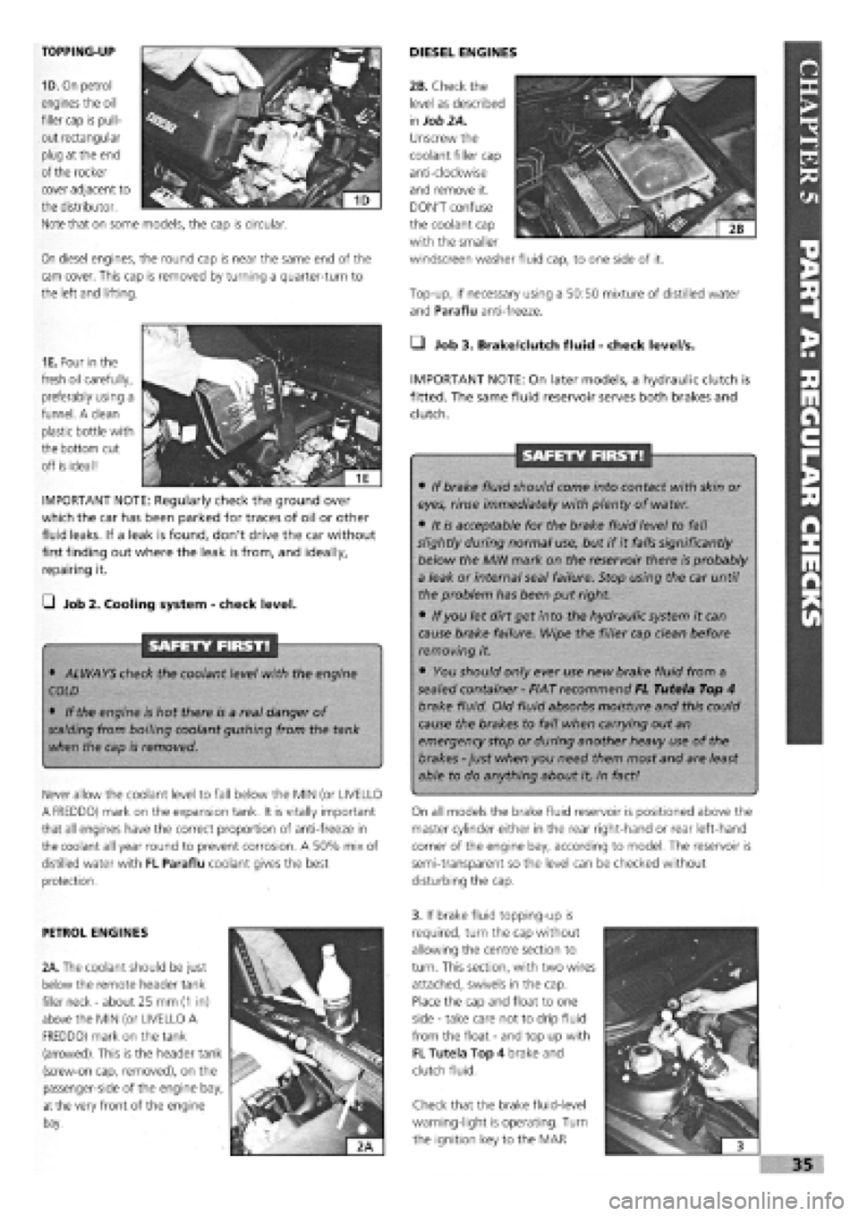
TOPPING-UP
1D. On petrol
engines the oil
filler cap is pull-
out rectangular
plug at the end
of the rocker
On diesel engines, the round cap is near the same end of the
cam cover. This cap is removed by turning a quarter-turn to
the left and lifting.
DIESEL ENGINES
Top-up, if necessary using a 50:50 mixture of distilled water
and Paraflu anti-freeze.
cover adjacent to
the distributor.
Note that on some models, the cap is circular.
1E. Pour in the
fresh oil carefully,
preferably using a
funnel. A clean
plastic bottle with
the bottom cut
off is ideal!
IMPORTANT NOTE: Regularly check the ground over
which the car has been parked for traces of oil or other
fluid leaks. If a leak is found, don't drive the car without
first finding out where the leak is from, and ideally,
repairing it.
G Job 2. Cooling system
-
check level.
SAFETY FIRST!
• ALWAYS check the coolant level with the engine
COLD
• If the engine is hot there is a real danger of
scalding
from boiling coolant gushing from the tank
when the cap is removed.
Never allow the coolant level to fall below the MIN (or UVELLO
A FREDDO) mark on the expansion tank. It is vitally important
that all engines have the correct proportion of anti-freeze in
the coolant all year round to prevent corrosion. A 50% mix of
distilled water with FL Paraflu coolant gives the best
protection.
• Job 3. Brake/dutch fluid
-
check level/s.
IMPORTANT NOTE: On later models, a hydraulic clutch is
fitted. The same fluid reservoir serves both brakes and
clutch.
SAFETY FIRST!
• If brake fluid should come into contact with skin or
eyes, rinse immediately with plenty of water.
• It is acceptable for the brake fluid level to fall
slightly during normal use, but if it falls significantly
below the MIN mark on the reservoir there is probably
a leak or internal seal failure. Stop using the car until
the problem has been put right.
• If you let dirt get into the hydraulic system it can
cause brake failure. Wipe the filler cap clean before
removing it.
• You should only ever use new brake fluid from a
sealed container
-
FIAT recommend FL Tutela Top 4
brake fluid. Old fluid absorbs moisture and this could
cause the brakes to fail when carrying out an
emergency stop or during another heavy use of the
brakes
-
just when you need them most and are least
able to do anything about it, in fact!
On all models the brake fluid reservoir is positioned above the
master cylinder either in the rear right-hand or rear left-hand
corner of the engine bay, according to model. The reservoir is
semi-transparent so the level can be checked without
disturbing the cap.
PETROL ENGINES
2A. The coolant should be just
below the remote header tank
filler neck
-
about 25 mm
(1
in)
above the MIN (or UVELLO A
FREDDO) mark on the tank
(arrowed). This is the header tank
(screw-on cap, removed), on the
passenger-side of the engine bay,
at
the very front of the engine
bay.
3. If brake fluid topping-up is
required, turn the cap without
allowing the centre section to
turn. This section, with two wires
attached, swivels in the cap.
Place the cap and float to one
side
-
take care not to drip fluid
from the float
-
and top up with
FL Tutela Top 4 brake and
clutch fluid.
Check that the brake fluid-level
warning-light is operating. Turn
the ignition key to the MAR
I
i 3
»35
2B. Check the
level as described
in
Job 2A.
Unscrew the
coolant filler cap
anti-clockwise
and remove it.
DON'T confuse
the coolant cap
with the smaller
windscreen washer fluid cap, to one side of it.
Page 42 of 171
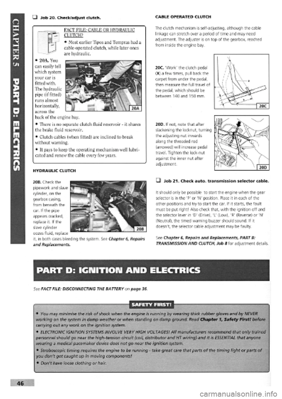
• Job 20. Check/adjust clutch. CABLE OPERATED CLUTCH
The clutch mechanism is self-adjusting, although the cable
linkage can stretch over a period of time and may need
adjustment. The adjuster is on top of the gearbox, reached
from inside the engine bay.
20C. 'Work' the clutch pedal
(X) a few times, pull back the
carpet from under the pedal,
then measure the full travel of
the pedal, which should be
between 140 and 150 mm.
/
\
/ \
/ u / Xl
1 ' ' / . V y 2
Jdi V 1 \
X. 1 —
20C
HYDRAULIC CLUTCH
20B. Check the
pipework and slave
cylinder, on the
gearbox casing,
from beneath the
20D. If not, note that after
slackening the locknut, turning
the adjusting nut inwards
along the threaded rod
(arrowed) will increase pedal
travel. Tighten the lock-nut
against the inner nut after
adjustment.
• Job 21. Check auto, transmission selector cable.
It should only be possible to start the engine when the gear
selector is in the 'P' or 'N' position. Place it in each of the
other positions and try to start the car. If it starts, the fault
must be put right! Also check that, with the ignition off and
the selector lever in 'D' (Drive), 'L' (Low), 'R' (Reverse) or 'N'
(Neutral), the timed warning buzzer should sound. If it
doesn't, the selector cable adjustment may be faulty.
See Chapter
6,
Repairs and Replacements, PART B:
TRANSMISSION AND CLUTCH, Job 8 for adjustment details.
PART D: IGNITION AND ELECTRICS
See FACT FILE: DISCONNECTING THE BATTERY on page 36
SAFETY FIRST!
• You may minimise the risk of shock when the engine is running by wearing thick rubber gloves and by NEVER
working on the system in damp weather or when standing on damp ground. Read Chapter 1, Safety First! before
carrying out any work on the ignition system.
• ELECTRONIC IGNITION SYSTEMS INVOLVE VERY HIGH VOLTAGES! All manufacturers recommend that only trained
personnel should go near the high-tension circuit (coil, distributor and HT wiring) and it is ESSENTIAL that anyone
wearing a medical pacemaker device does not go near the ignition system.
• Stroboscopic timing requires the engine to be running
-
take great care that parts of the timing light or parts of
you don't get caught up in moving components!
• Don't have loose clothing or hair.
46
FACT FILE: CABLE OR HYDRAULIC
CLUTCH?
• Most earlier Tipos and Tempras had a
cable-operated clutch, while later ones
are hydraulic.
• 2 OA. You
can easily tell
which system
your car is
fitted with.
The hydraulic
pipe (if fitted)
runs almost
horizontally,
across the
back of the engine bay.
• There is no separate clutch fluid reservoir
-
it shares
the brake fluid reservoir.
• Clutch cables (when fitted) are inclined to break
without warning.
• It pays to keep the operating mechanism well lubri-
cated and renew the cable every few years.
car. If the pipe
appears cracked,
replace it. If the
slave cylinder
oozes fluid, replace
it, in both cases bleeding the system. See Chapter
6,
Repairs
and Replacements.
Page 54 of 171
each track rod end (TRE). Also, look out for a split gaiter.
Replace the TRE if the gaiter is split, or it will rapidly fail.
E3 INSIDE INFORMATION: Try placing your hand over the
TRE as the steering is moved. If there are any signs of
wear, replace the TRE. Q
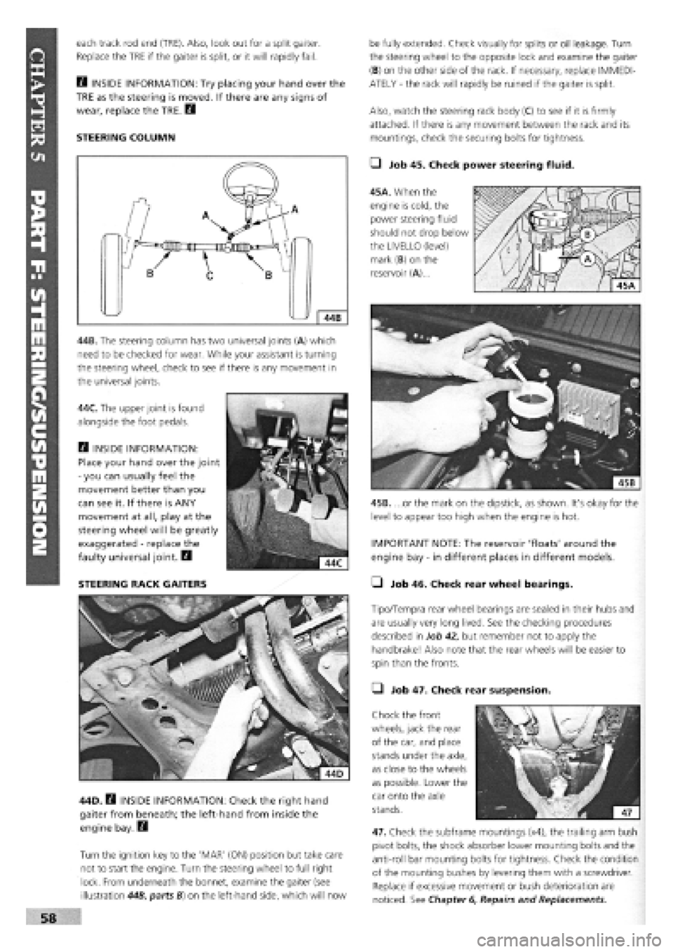
STEERING COLUMN
44B. The steering column has two universal joints (A) which
need to be checked for wear. While your assistant is turning
the steering wheel, check to see if there is any movement in
the universal joints.
44C. The upper joint is found
alongside the foot pedals.
Q INSIDE INFORMATION:
Place your hand over the joint
-
you can usually feel the
movement better than you
can see it. If there is ANY
movement at all, play at the
steering wheel will be greatly
exaggerated
-
replace the
faulty universal joint. B
STEERING RACK GAITERS
44D. B INSIDE INFORMATION: Check the right hand
gaiter from beneath; the left-hand from inside the
engine bay. Q
Turn the ignition key to the 'MAR' (ON) position but take care
not to start the engine. Turn the steering wheel to full right
lock. From underneath the bonnet, examine the gaiter (see
illustration 44B, parts B) on the left-hand side, which will now
be fully extended. Check visually for splits or oil leakage. Turn
the steering wheel to the opposite lock and examine the gaiter
(B) on the other side of the rack. If necessary, replace IMMEDI-
ATELY
-
the rack will rapidly be ruined if the gaiter is split.
Also, watch the steering rack body (C) to see if it is firmly
attached. If there is any movement between the rack and its
mountings, check the securing bolts for tightness.
• Job 45. Check power steering fluid.
45A. When the
engine is cold, the
power steering fluid
should not drop below
the LIVELLO (level)
mark (B) on the
reservoir (A)...
45B. ...or the mark on the dipstick, as shown. It's okay for the
level to appear too high when the engine is hot.
IMPORTANT NOTE: The reservoir 'floats' around the
engine bay
-
in different places in different models.
• Job 46. Check rear wheel bearings.
Tipo/Tempra rear wheel bearings are sealed in their hubs and
are usually very long lived. See the checking procedures
described in Job 42, but remember not to apply the
handbrake! Also note that the rear wheels will be easier to
spin than the fronts.
• Job 47. Check rear suspension.
Chock the front
wheels, jack the rear
of the car, and place
stands under the axle,
as close to the wheels
as possible. Lower the
car onto the axle
stands.
47. Check the subframe mountings (x4), the trailing arm bush
pivot bolts, the shock absorber lower mounting bolts and the
anti-roll bar mounting bolts for tightness. Check the condition
of the mounting bushes by levering them with a screwdriver.
Replace if excessive movement or bush deterioration are
noticed. See Chapter
6,
Repairs and Replacements.
Page 56 of 171

49H. ...and push out the nylon bush (arrowed). Reassemble
on the new pad and reattach the wire.
IMPORTANT NOTE: After fitting the pads, apply the
brakes firmly several times to adjust them.
• Job 50. Check rear brakes.
SAFETY FIRST!
Read SAFETY FIRST at the start of Job 49 before
proceeding!
GENERAL. The majority of Tipo/Tempra models are fitted with
rear drum-type rear brakes, but models with ABS anti-lock
braking have a disc-and-caliper arrangement instead.
Slacken the wheel bolts, raise the wheel, remove it and
support the car with an axle stand. Make sure that the wheels
remaining on the ground are chocked in both directions and
that the handbrake is off.
DRUM REAR BRAKES
If the drum
sticks,
try:
• screwing a pair of
bolts
into the two threaded
holes in the drum. Evenly
tightening the bolts will force the drum off the
shoes.
• tapping carefully around the drum with a hide
mallet to help loosen it.
s Vn order to fit new pads,
r> - the caliper piston must be
pushed back into the bore.
• Use an old battery hydrometer to draw about half
of the fluid from the master cylinder.
• Push the piston back into the caliper, using a G-
clamp.
• Keep an eye on the master cylinder so that it
doesn't overflow as fluid is pushed back up the pipe.
IMPORTANT NOTE: Be very sparing or grease could
migrate to the friction linings!
WEAR SENSORS I I There are certain essential checks you
should carry out for yourself, with brake
pads removed:
• Look for any obvious grooves worn into the disc.
Slight undulations are acceptable, but anything worse
and the disc should be replaced.
• Look and feel for any wear-ridge on the outer edges
of the disc. The depth will give an indication of wear.
• Check for corrosion of the disc surface. If any is
found, the brake caliper is probably faulty, and needs
checking.
• If any surface flaking is found on either side of the
disc, replace them both.
• If you are not certain whether any wear is acceptable,
ask your specialist or FIAT dealer to check.
FACT FILE: BRAKE DISC WEAR
SYMPTOMS
Before reassembling the brake, check the condition of the
brake caliper. Have an assistant VERY SLOWLY AND GENTLY
apply pressure to the brake pedal while you watch the piston
(see illustration 49B, part
8),
which should move outwards. If
it doesn't easily move, it is seized and the caliper should be
replaced. DO NOT allow the piston to project more than 10
mm or it may be forced from the caliper
-
use a G-clamp as an
'end stop'.
49F. Before
fitting the pads,
put a light smear
of brake grease
(NOT ordinary
grease) on the
pads' metal
backplates at the
points shown.
49G. If these are fitted, the contact has to be transferred from
the old backing plate to the new. Pull off the wire, push out
the brass pin...
49E. Check inside
the caliper housing
for signs of
corrosion. If any is
found, or the seal is
damaged, the caliper
should be exchanged
for a new or
overhauled unit from
your FIAT dealership.
Examine the piston's protective gaiter (see illustration 49B,
part 9) for splitting and fluid leaks. This one is in poor
condition and the caliper requires immediate replacement.
Page 57 of 171
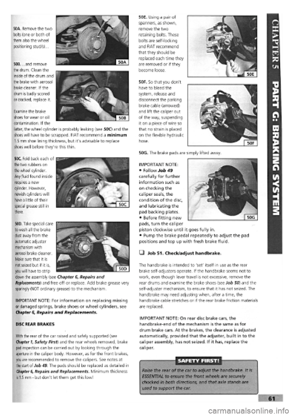
50A. Remove the two
bolts
(one or both of
them also the wheel
positioning stud/s)...
50B. ...and remove
the
drum.
Clean the
inside of the drum and
the brake with aerosol
brake
cleaner. If the
drum is badly scored
or cracked,
replace it.
50F. So that you don't
have to bleed the
system, release and
disconnect the parking
brake cable (arrowed)
and lift the caliper out
of the way, suspending
it on a piece of wire so
that no strain is placed
on the flexible hydraulic
hose.
50G. The brake pads are simply lifted away.
50E. Using a pair of
spanners, as shown,
remove the two
retaining bolts. These
bolts are self-locking
and FIAT recommend
that they should be
replaced each time they
are removed or if they
become loose.
Examine the brake
shoes
for wear or oil
contamination. If the
latter, the wheel cylinder is probably leaking (see 50C) and the
shoes will
have to be scrapped. FIAT recommend a minimum
1.5 mm
shoe lining thickness, but it's advisable to replace
shoes
well before they're this thin.
50C. Fold back each of
the
two rubbers on
the wheel
cylinder.
Any
fluid
found inside
requires a new
cylinder. However,
newish cylinders will
have a
little of their
special grease still in
there.
. """
€
Sjjj
KV,1
| 50D|
50D. Take
special care
to wash
all the brake
dust
away from the
automatic adjuster
mechanism with
aerosol brake cleaner.
Make
sure that it is
not seized
but if it is,
you will
have to strip
down
the assembly (see Chapter
6,
Repairs and
Replacements)
and free off or replace. Add brake grease very
sparingly (NOT ordinary grease) to the mechanism.
IMPORTANT NOTE: For information on replacing missing
or damaged springs, brake shoes or wheel cylinders, see
Chapter
6,
Repairs and Replacements.
DISC REAR BRAKES
With
the rear of the car raised and safely supported (see
Chapter 1,
Safety First) and the rear wheels removed, brake
pad
inspection can be carried out by looking through the
aperture in the caliper body. However, as for the front brakes,
you are
recommended to remove the calipers. See notes at
the
start of Job
49.
The pads should be replaced as detailed in
Chapter 6,
Repairs and Replacements. Minimum thickness
is 1.5 mm -
but don't let them get this low!
• Job 51. Check/adjust handbrake.
The handbrake is intended to 'set' itself in use as the rear
brake self-adjusters operate. If the handbrake seems not to
work, even though lever travel is not excessive, remove the
rear drums and examine the brake shoes (see Job 50) and the
self-adjuster mechanism, to ensure that it has not seized. The
handbrake may need adjusting when, after a time, the
handbrake cable stretches or if the rear brake friction materials
are replaced.
IMPORTANT NOTE: On rear disc brake cars, the
handbrake-end of the mechanism is the same as for
drum brake cars. At the brakes, the clearance is adjusted
automatically, provided that the adjuster, built in to the
caliper assembly, has not seized. If it has, replace the
caliper.
SAFETY FIRST!
Raise the rear of the car to adjust the handbrake. It
is
ESSENTIAL to ensure the front wheels are securely
chocked in both directions, and that axle stands are
used to support the car.
IMPORTANT NOTE:
• Follow Job 49
carefully for further
information such as
on checking the
caliper seals, the
condition of the disc,
and lubricating the
pad backing plates.
• Before fitting new
pads, turn the caliper
piston clockwise until it goes fully in.
• Pump the brake pedal repeatedly to adjust the pad
positions and top up with fresh brake fluid.
Page 58 of 171
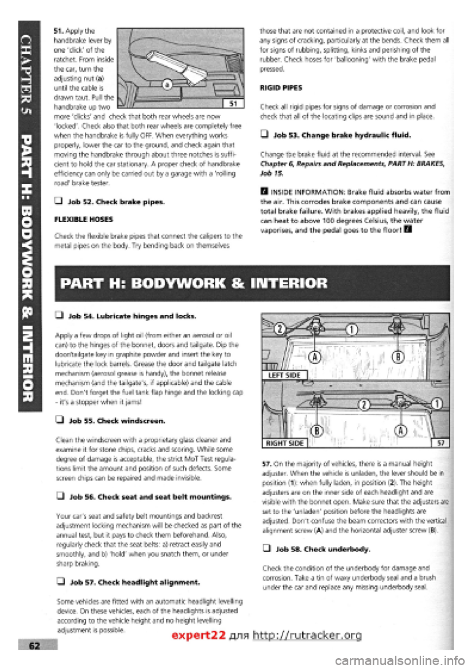
51. Apply the
handbrake lever by
one 'click' of the
ratchet. From inside
the car, turn the
adjusting nut (a)
until the cable is
drawn taut. Pull the
handbrake up two
more 'clicks' and check that both rear wheels are now
'locked'. Check also that both rear wheels are completely free
when the handbrake is fully OFF. When everything works
properly, lower the car to the ground, and check again that
moving the handbrake through about three notches is suffi-
cient to hold the car stationary. A proper check of handbrake
efficiency can only be carried out by a garage with a 'rolling
road' brake tester.
Q Job 52. Check brake pipes.
FLEXIBLE HOSES
Check the flexible brake pipes that connect the calipers to the
metal pipes on the body. Try bending back on themselves
those that are not contained in a protective coil, and look for
any signs of cracking, particularly at the bends. Check them all
for signs of rubbing, splitting, kinks and perishing of the
rubber. Check hoses for 'ballooning' with the brake pedal
pressed.
RIGID PIPES
Check all rigid pipes for signs of damage or corrosion and
check that all of the locating clips are sound and in place.
• Job 53. Change brake hydraulic fluid.
Change the brake fluid at the recommended interval. See
Chapter
6,
Repairs and Replacements, PART H: BRAKES,
Job 15.
H INSIDE INFORMATION: Brake fluid absorbs water from
the air. This corrodes brake components and can cause
total brake failure. With brakes applied heavily, the fluid
can heat to above 100 degrees Celsius, the water
vaporises, and the pedal goes to the floor! B
PART H: BODYWORK & INTERIOR
• Job 54. Lubricate hinges and locks.
Apply a few drops of light oil (from either an aerosol or oil
can) to the hinges of the bonnet, doors and tailgate. Dip the
door/tailgate key in graphite powder and insert the key to
lubricate the lock barrels. Grease the door and tailgate latch
mechanism (aerosol grease is handy), the bonnet release
mechanism (and the tailgate's, if applicable) and the cable
end. Don't forget the fuel tank flap hinge and the locking cap
- it's a stopper when it jams!
• Job 55. Check windscreen.
Clean the windscreen with a proprietary glass cleaner and
examine it for stone chips, cracks and scoring. While some
degree of damage is acceptable, the strict MoT Test regula-
tions limit the amount and position of such defects. Some
screen chips can be repaired and made invisible.
• Job 56. Check seat and seat belt mountings.
Your car's seat and safety belt mountings and backrest
adjustment locking mechanism will be checked as part of the
annual test, but it pays to check them beforehand. Also,
regularly check that the seat belts: a) retract easily and
smoothly, and b) 'hold' when you snatch them, or under
sharp braking.
Q Job 57. Check headlight alignment.
Some vehicles are fitted with an automatic headlight levelling
device. On these vehicles, each of the headlights is adjusted
according to the vehicle height and no height levelling
adjustment is possible.
57. On the majority of vehicles, there is a manual height
adjuster. When the vehicle is unladen, the lever should be in
position (1): when fully laden, in position (2). The height
adjusters are on the inner side of each headlight and are
visible with the bonnet open. Make sure that the adjusters are
set to the 'unladen' position before the headlights are
adjusted. Don't confuse the beam correctors with the vertical
alignment screw (A) and the horizontal adjuster screw (B).
• Job 58. Check underbody.
Check the condition of the underbody for damage and
corrosion. Take a tin of waxy underbody seal and a brush
under the car and replace any missing underbody seal.
expert22 fl/ia http://rutracker.org
RIGHT SIDE