1987 SUZUKI GRAND VITARA brake fluid
[x] Cancel search: brake fluidPage 413 of 962
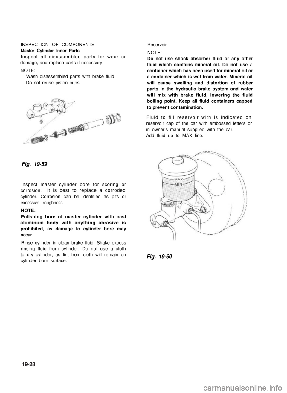
INSPECTION OF COMPONENTS
Master Cylinder Inner Parts
Inspect all disassembled parts for wear or
damage, and replace parts if necessary.
NOTE:
Wash disassembled parts with brake fluid.
Do not reuse piston cups.
Reservoir
NOTE:
Do not use shock absorber fluid or any other
fluid which contains mineral oil. Do not use a
container which has been used for mineral oil or
a container which is wet from water. Mineral oil
will cause swelling and distortion of rubber
parts in the hydraulic brake system and water
will mix with brake fluid, lowering the fluid
boiling point. Keep all fluid containers capped
to prevent contamination.
Fluid to fill reservoir with is indicated on
reservoir cap of the car with embossed letters or
in owner’s manual supplied with the car.
Add fluid up to MAX line.
Fig. 19-59
Inspect master cylinder bore for scoring or
corrosion.It is best to replace a corroded
cylinder. Corrosion can be identified as pits or
excessive roughness.
NOTE:
Polishing bore of master cylinder with cast
aluminum body with anything abrasive is
prohibited, as damage to cylinder bore may
occur.
Rinse cylinder in clean brake fluid. Shake excess
rinsing fluid from cylinder. Do not use a cloth
to dry cylinder, as lint from cloth will remain on
cylinder bore surface.Fig. 19-60
19-28
Page 414 of 962
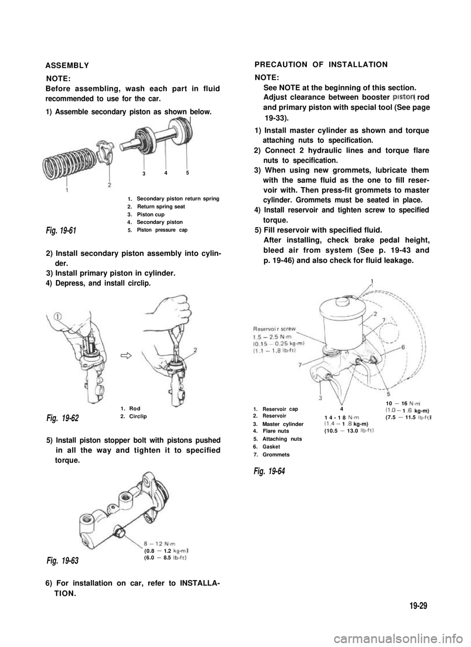
ASSEMBLYPRECAUTION OF INSTALLATION
NOTE:NOTE:
Before assembling, wash each part in fluidSee NOTE at the beginning of this section.
recommended to use for the car.Adjust clearance between booster piston rod
1) Assemble secondary piston as shown below.
FBh
and primary piston with special tool (See page
19-33).
Fig. 19-61
1) Install master cylinder as shown and torque
attaching nuts to specification.
2) Connect 2 hydraulic lines and torque flare
1.
2.
3.
4.
5.
I I345
Secondary piston return spring
Return spring seat
Piston cupSecondary piston
Piston pressure cap
2) Install secondary piston assembly into cylin-
der.
3) Install primary piston in cylinder.
4) Depress, and install circlip.
nuts to specification.
3) When using new grommets, lubricate them
with the same fluid as the one to fill reser-
voir with. Then press-fit grommets to master
cylinder. Grommets must be seated in place.
4) Install reservoir and tighten screw to specified
torque.
5) Fill reservoir with specified fluid.
After installing, check brake pedal height,
bleed air from system (See p. 19-43 and
p. 19-46) and also check for fluid leakage.
:
Fig. 19-622. Circlip
1. Rod
5) Install piston stopper bolt with pistons pushed
in all the way and tighten it to specified
torque.
(0.8 - 1.2 kam)
1.Reservoir10 - 16 N.mcap42.Reservoir(1 .O - 1 .6 kg-m)14-18N.m(7.5 - 11.5 lb-ftl--I3.Master cylinder(1 .4 - 1.8 kg-m)4.Flare nuts(10.5 -13.0 lb-ft)
5.Attaching nuts
6.Gasket
7.Grommets
Fig. 19-64
Fig. 19-63(6.0 - 8.5 lb-ft).
6) For installation on car, refer to INSTALLA-
TION.
19-29
Page 415 of 962
19-5. BRAKE BOOSTERDISASSEMBLY
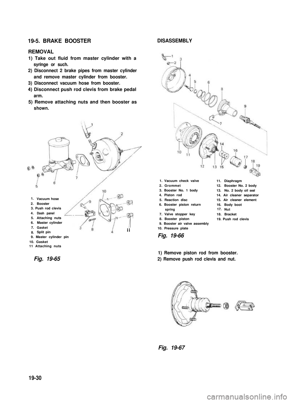
REMOVAL
1) Take out fluid from master cylinder with a
syringe or such.
2) Disconnect 2 brake pipes from master cylinder
and remove master cylinder from booster.
3) Disconnect vacuum hose from booster.
4) Disconnect push rod clevis from brake pedal
arm.
5) Remove attaching nuts and then booster as
shown.
Vacuum hose
2.Booster3. Push rod clevis
4.Dash panel5.Attaching nuts6.Master cylinder
7.Gasket
8. Split pin
9. Master cylinder pin
10. Gasket11 Attaching nuts
Fig. 19-65
49
-@P
Iii
1. Vacuum check valve
2. Grommet3. Booster No. 1 body4. Piston rod
5. Reaction disc6. Booster piston return
spring7. Valve stopper key8. Booster piston9. Booster air valve assembly10. Pressure plate
Fig. 19-66
11.Diaphragm12.Booster No. 2body
13.No. 2 body oilseal14. Air cleaner separator15. Air cleaner element
16.Body bootNut
18.Bracket
19. Push rod clevis
1) Remove piston rod from booster.
2) Remove push rod clevis and nut.
Fig. 19-67
19-30
1.
17.
Page 422 of 962
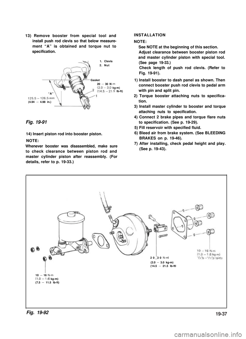
13) Remove booster from special tool and
install push rod clevis so that below measure-
ment “A” is obtained and torque nut to
specification.
-41. Clevis
2. Nut
Gasket20 - 30 N
“A”
125.5- 126.5mm(4.94 - 4.98 in.)\
.rnkg-m).5 lb-ft)
Fig. 19-91
14) Insert piston rod into booster piston.
NOTE:
Whenever booster was disassembled, make sure
to check clearance between piston rod and
INSTALLATION
NOTE:
See NOTE at the beginning of this section.
Adjust clearance between booster piston rod
and master cylinder piston with special tool.
(See page 19-33.)
Check length of push rod clevis. (Refer to
Fig. 19-91).
1) Install booster to dash panel as shown. Then
connect booster push rod clevis to pedal arm
with pin and split pin.
2) Torque booster attaching nuts to specifica-
tion.
3) Install master cylinder to booster and torque
attaching nuts to specification.
4) Connect 2 brake pipes and torque flare nuts
to specification. (See p. 19-29).
5) Fill reservoir with specified fluid.
6) Bleed air from brake system. (See BLEEDING
BRAKES on p. 19-46).
7) After installing, check pedal height and play.
(See p. 19-43).
master cylinder piston after reassembly. (For
details, refer to p. 19-33.)
20 30 N.m-(2.0 - 3.0 kg-m)(14.5 - 21.5 lb-ftl
10 - 16 N.m(1.0-1.6 kg-m)(7.5 - 11.5 lb-ft)
Fig. 19-9219-37
Page 424 of 962
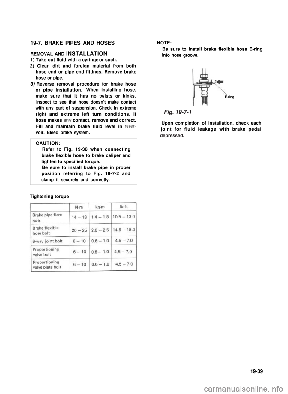
19-7. BRAKE PIPES AND HOSES
REMOVAL AND INSTALLATION
1) Take out fluid with a cyringe or such.
2) Clean dirt and foreign material from both
hose end or pipe end fittings. Remove brake
hose or pipe.
3) Reverse removal procedure for brake hose
or pipe installation.When installing hose,
make sure that it has no twists or kinks.
Inspect to see that hose doesn’t make contact
with any part of suspension. Check in extreme
right and extreme left turn conditions. If
hose makes .any contact, remove and correct.
Fill and maintain brake fluid level in reser-
voir. Bleed brake system.
NOTE:
Be sure to install brake flexible hose E-ring
into hose groove.
z+
\E-ring
Upon completion of installation, check each
joint for fluid leakage with brake pedal
CAUTION:I
Refer to Fig. 19-38 when connecting
brake flexible hose to brake caliper and
tighten to specified torque.
Be sure to install brake pipe in proper
position referring to Fig. 19-7-2 and
clamp it securely and correctly.
Tightening torque
19-39
Fig. 19-7-1
depressed.
Page 427 of 962
19-8. MAINTENANCE SERVICE
ROAD TESTING BRAKES
Brakes should be tested on dry, clean, smooth
and reasonably level roadway which is not
crowned. Road test brakes by making brake
applications with both light and heavy pedal
forces at various speeds to determine if the car
stops evenly and effectively.
Also drive car to see if it leads to one side or the
other without brake application. If it does,
check tire pressure, front end alignment and
front suspension attachments for looseness.
See diagnosis chart for other causes.
BRAKE FLUID LEAKS
Check master cylinder fluid levels. While a slight
drop in reservoir level does result from normal
lining wear, an abnormally low level indicates a
leak in the system.In such a case, check the
entire brake system for leakage. If even a slight
evidence of leakage is noted, the cause should be
corrected or defective parts should be replaced.
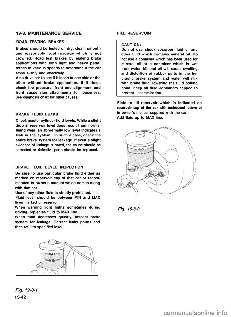
BRAKE FLUID LEVEL INSPECTION
Be sure to use particular brake fluid either as
marked on reservoir cap of that car or recom-
mended in owner’s manual which comes along
with that car.
Use of any other fluid is strictly prohibited.
Fluid level should be between MIN and MAX
lines marked on reservoir.
When warning light lights sometimes during
driving, replenish fluid to MAX line.
When fluid decreases quickly, inspect brake
system for leakage. Correct leaky points and
then refill to specified level.
FILL RESERVOIR
CAUTION:
Do not use shock absorber fluid or any
other fluid which contains mineral oil. Do
not use a container which has been used for
mineral oil or a container which is wet
from water. Mineral oil will cause swelling
and distortion of rubber parts in the hy-
draulic brake system and water will mix
with brake fluid, lowering the fluid boiling
point. Keep all fluid containers capped to
prevent contamination.
Fluid to fill reservoir which is indicated on
reservoir cap of the car with embossed letters or
in owner’s manual supplied with the car.
Add fluid up to MAX line.
Fig. 19-8-2
Fig. 19-8-1
19-42
Page 430 of 962
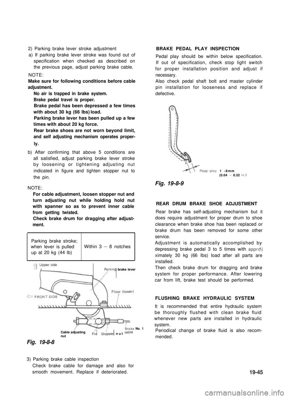
2) Parking brake lever stroke adjustment
a) If parking brake lever stroke was found out of
specification when checked as described on
the previous page, adjust parking brake cable.
NOTE:
Make sure for following conditions before cable
adjustment.
No air is trapped in brake system.
Brake pedal travel is proper.
Brake pedal has been depressed a few times
with about 30 kg (66 lbs) load.
Parking brake lever has been pulled up a few
times with about 20 kg force.
Rear brake shoes are not worn beyond limit,
and self adjusting mechanism operates proper-
ly.
b) After confirming that above 5 conditions are
all satisfied, adjust parking brake lever stroke
by loosening or tightening adjusting nut
indicated in figure and tighten stopper nut to
the pin.
NOTE:
For cable adjustment, loosen stopper nut and
turn adjusting nut while holding hold nut
with spanner so as to prevent inner cable
from getting twisted.
Check brake drum for dragging after adjust-
ment.
Parking brake stroke;
when lever is pulledWithin 3 - 8 notches
up at 20 kg (44 lb)
’ yLyFrking brake lever
Cable adjustingnutPi:St&per nut cab’e
Fig. 19-8-8
No. 1
BRAKE PEDAL PLAY INSPECTION
Pedal play should be within below specification.
If out of specification, check stop light switch
for proper installation position and adjust if
necessary.
Also check pedal shaft bolt and master cylinder
pin installation for looseness and replace if
defective.
play1 -8mm(0.04 - 0.32tn.1
Fig. 19-8-9
REAR DRUM BRAKE SHOE ADJUSTMENT
Rear brake has self-adjusting mechanism but it
does require adjustment for proper drum to shoe
clearance when brake shoe has been replaced or
brake drum has been removed for some other
service.
Adjustment is automatically accomplished by
depressing brake pedal 3 to 5 times with apprd-
ximately 30 kg (66 Ibs) load after all parts are
installed.
Then check brake drum for dragging and brake
system for proper performance. After lowering
car from lift, brake test should be performed.
FLUSHING BRAKE HYDRAULIC SYSTEM
It is recommended that entire hydraulic system
be thoroughly flushed with clean brake fluid
whenever new parts are installed in hydraulic
system.
Periodical change of brake fluid is also recom-
mended.
3) Parking brake cable inspection
Check brake cable for damage and also for
smooth movement. Replace if deteriorated.19-45
Page 431 of 962
BLEEDING BRAKES
NOTE:
Brake fluid is extremely damaging to paint. If
fluid should accidentally touch painted surface,
immediately wipe fluid from paint and clean
painted surface.
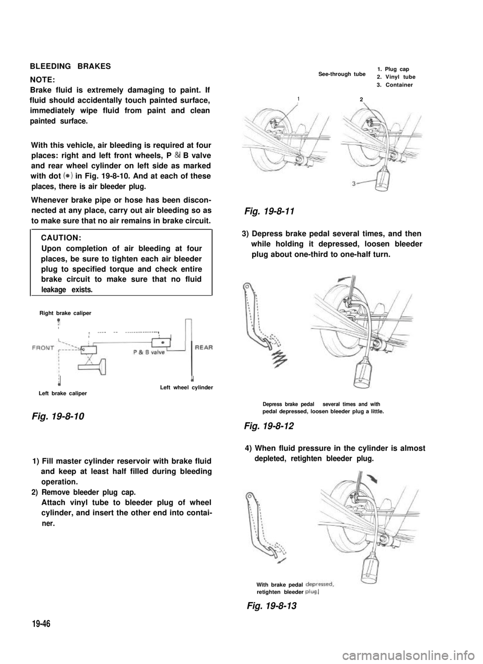
With this vehicle, air bleeding is required at four
places: right and left front wheels, P & B valve
and rear wheel cylinder on left side as marked
with dot (0) in Fig. 19-8-10. And at each of these
places, there is air bleeder plug.
Whenever brake pipe or hose has been discon-
nected at any place, carry out air bleeding so as
to make sure that no air remains in brake circuit.
CAUTION:
Upon completion of air bleeding at four
places, be sure to tighten each air bleeder
plug to specified torque and check entire
brake circuit to make sure that no fluid
leakage exists.
Right brake caliper
?Ir ____ -- ---------------,IIAn
i
Left brake caliper
1Left wheel cylinder
Fig. 19-8-10
1) Fill master cylinder reservoir with brake fluid
and keep at least half filled during bleeding
operation.
2) Remove bleeder plug cap.
Attach vinyl tube to bleeder plug of wheel
cylinder, and insert the other end into contai-
ner.
See-through tube1. Plug cap2. Vinyl tube
2
3. Container
1
Fig. 19-8-11
3) Depress brake pedal several times, and then
while holding it depressed, loosen bleeder
plug about one-third to one-half turn.
Depress brake pedal several times and withpedal depressed, loosen bleeder plug a little.
Fig. 19-8-12
4) When fluid pressure in the cylinder is almost
depleted, retighten bleeder plug.
With brake pedalretighten bleederplug.
Fig. 19-8-13
19-46