Page 394 of 962
![SUZUKI GRAND VITARA 1987 Service Repair Manual [Rear brake OPERATION]
With the general drum brake type, when the
brake pedal is depressed, two pistons in the
wheel cylinder force the brake shoes outward,
restraining the turn of the drum.
The more SUZUKI GRAND VITARA 1987 Service Repair Manual [Rear brake OPERATION]
With the general drum brake type, when the
brake pedal is depressed, two pistons in the
wheel cylinder force the brake shoes outward,
restraining the turn of the drum.
The more](/manual-img/20/57437/w960_57437-393.png)
[Rear brake OPERATION]
With the general drum brake type, when the
brake pedal is depressed, two pistons in the
wheel cylinder force the brake shoes outward,
restraining the turn of the drum.
The more the brake shoes get worn, the longer
distance the pistons must move. As a result, the
brake pedal travel (pedal-to-wall clearance)
increases. Then the shoe clearance must be
adjusted by the shoe adjusting screws. Thus
periodical adjustment is required for the drum
brake type in general.
This rear brake is provided with a self-adjusting
system which automatically adjusts the shoe-to-
drum clearance (pedal-to-wall clearance) caused
by such brake shoe wear.
Clearance correction
In each rear wheel cylinder, pistons, piston cups,
and a piston spring (1) are installed. When the
brake pedal is depressed, fluid pressure is applied
to the inside of the chamber on the piston (2),
(3).
Being actuated by this pressure, the piston (2)
moves to the left (piston (3) moves to the right)
in the following figure and presses the brake
shoe against the brake drum, thus producing
brake force.
(2)(3)
Fig. 19-9
At this time, the distance the brake shoe moves
is “B”,that is, the distance that “A” (the end of
the long hole made in the brake shoes web)
moves till it contacts the lever (1) which is fitted
in the long hole.
Fig. 19-10
When the brake pedal is depressed, the piston
and brake shoe move toward the brake drum
side by the aforementioned distance “B” and
“A” of the brake shoe web contacts the lever
(1). As the brake shoe gets worn and the brake
shoe clearance becomes larger, the force applied
to the lever (1) at the time of such a contact
becomes larger. When it exceeds 10 - 12 kg
(22 - 26 Ibs), the “A” of the brake shoe web
moves the lever (1) as much as the amount of
the brake shoe lining wear toward the direction
as shown with an arrow in the figure. Thus the
shoe is forced against the drum and the brake
force is produced.
19-9
Page 400 of 962

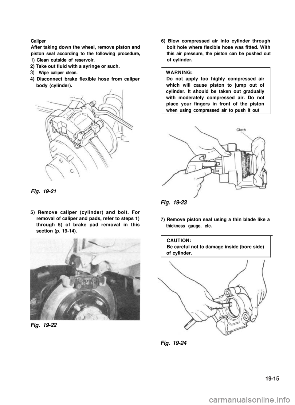
Caliper
After taking down the wheel, remove piston and
piston seal according to the following procedure,
1) Clean outside of reservoir.
2) Take out fluid with a syringe or such.
3)Wipe caliper clean.
4) Disconnect brake flexible hose from caliper
body (cylinder).
Fig. 19-21
6) Blow compressed air into cylinder through
bolt hole where flexible hose was fitted. With
this air pressure, the piston can be pushed out
of cylinder.
WARNING:
Do not apply too highly compressed air
which will cause piston to jump out of
cylinder. It should be taken out gradually
with moderately compressed air. Do not
place your fingers in front of the piston
when using compressed air to push it out
Fig. 19-23
5) Remove caliper (cylinder) and bolt. For
removal of caliper and pads, refer to steps 1)
through 5) of brake pad removal in this
section (p. 19-14).
Fig. 19-22
7) Remove piston seal using a thin blade like a
thickness gauge, etc.
CAUTION:
Be careful not to damage inside (bore side)
of cylinder.1
Fig. 19-24
19-15
Page 401 of 962
Disc
1) After taking down the wheel, remove caliper
assembly by loosening carrier bolts (2 pcs).
CAUTION:
During removal, be careful not to damage
brake flexible hose and not to depress
brake pedal.II
Fig. 19-25
2) Remove disc by using 8 mm bolts @I (2 pcs).
INSPECTION OF COMPONENTS
Brake Pad
Check pad lining for wear. When wear exceeds
its limit, replace with a new one.
Fig. 19-27
~~
CAUTION :
Never polish pad lining with sandpaper. If
lining is polished with sandpaper, hard
particles of sandpaper will be deposited in
lining and may damage disc. When pad
lining requires correction, replace it with a
new one.
Pad thickness
(lining + pad rim)
NOTE:
When pads are removed, visually inspect caliper
for brake fluid leak. Correct leaky point, if any.
Fig. 19-26
19-16
Page 403 of 962

PRECAUTIONS ON INSTALLATION
Reassemble front brake in the reverse order
of disassembly, using care for the following
points.
CAUTION:
Wash each part cleanly before installation
in the same fluid as the one used in
master cylinder reservoir.
Never use other fluid or thinner.
Before installing piston and piston seal
to cylinder, apply fluid to them.
After reassembling brake line, bleed air
from lines.
Piston Seal
Piston seal is used to seal piston and cylinder
and to adjust clearance between pad and disc.
Replace with a new one at every overhaul. Fit
piston seal into groove in cylinder taking care
not to twist it.
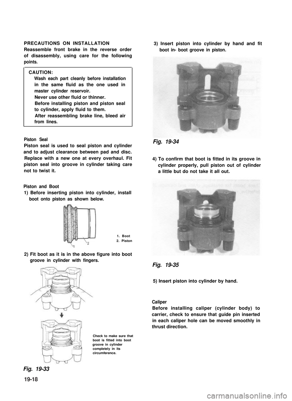
Piston and Boot
1) Before inserting piston into cylinder, install
boot onto piston as shown below.
1. Boot
2. Piston
2) Fit boot as it is in the above figure into boot
groove in cylinder with fingers.
Check to make sure thatboot is fitted into bootgroove in cylindercompletely in itscircumference.
3) Insert piston into cylinder by hand and fit
boot in- boot groove in piston.
Fig. 19-34
4) To confirm that boot is fitted in its groove in
cylinder properly, pull piston out of cylinder
a little but do not take it all out.
Fig. 19-35
5) Insert piston into cylinder by hand.
Caliper
Before installing caliper (cylinder body) to
carrier, check to ensure that guide pin inserted
in each caliper hole can be moved smoothly in
thrust direction.
Fig. 19-33
19-18
Page 404 of 962

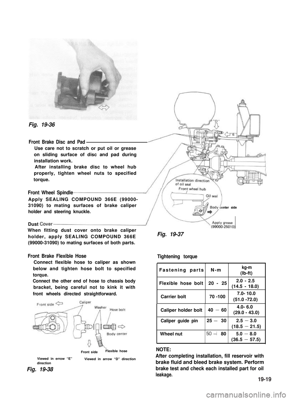
Fig. 19-36
Front Brake Disc and Pad
Use care not to scratch or put oil or grease
on sliding surface of disc and pad during
installation work.
After installing brake disc to wheel hub
properly, tighten wheel nuts to specified
torque.
Front Wheel Spindle
Apply SEALING COMPOUND 366E (99000-
31090) to mating surfaces of brake caliper
holder and steering knuckle.nter side
Dust Cover/
When fitting dust cover onto brake caliper
holder, apply SEALING COMPOUND 366E
(99000-31090) to mating surfaces of both parts.
Front Brake Flexible Hose
Connect flexible hose to caliper as shown
below and tighten hose bolt to specified
torque.
Connect the other end of hose to chassis body
bracket, being careful not to kink it with
front wheels directed straightforward.
\Front sideFlexible hose
Viewed in errow “E”Viewed in arrow “D” directiondirection
Fig. 19-38
V(gg!&
Fig. 19-37
Tightening torque
Fastening parts N-mkg-m
(lb-ft)
Flexible hose bolt 20 - 252.0 - 2.5
(14.5 -18.0)
Carrier bolt 70 -100
Caliper holder bolt 40 -60
Caliper guide pin25 -302.5-3.0
(18.5-21.5)
Wheel nut50-805.0-8.0
(36.5-57.5)
NOTE:
After completing installation, fill reservoir with
brake fluid and bleed brake system. Perform
brake test and check each installed part for oil
leakage.
(51.0 -72.0)
7.0- 10.0
4.0- 6.0
(29.0 - 43.0)
19-19
Page 406 of 962

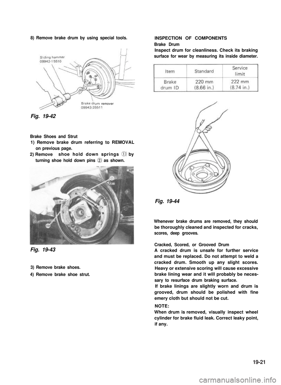
8) Remove brake drum by using special tools.
urn remover
Fig. 19-42
Brake Shoes and Strut
1) Remove brake drum referring to REMOVAL
on previous page.
2) Removeshoe hold down springs @ by
turning shoe hold down pins @ as shown.
Fig. 19-43
3) Remove brake shoes.
4) Remove brake shoe strut.
INSPECTION OF COMPONENTS
Brake Drum
Inspect drum for cleanliness. Check its braking
surface for wear by measuring its inside diameter.
Fig. 19-44
Whenever brake drums are removed, they should
be thoroughly cleaned and inspected for cracks,
scores, deep grooves.
Cracked, Scored, or Grooved Drum
A cracked drum is unsafe for further service
and must be replaced. Do not attempt to weld a
cracked drum. Smooth up any slight scores.
Heavy or extensive scoring will cause excessive
brake lining wear and it will probably be neces-
sary to resurface drum braking surface.
If brake linings are slightly worn and drum is
grooved, drum should be polished with fine
emery cloth but should not be cut.
NOTE:
When drum is removed, visually inspect wheel
cylinder for brake fluid leak. Correct leaky point,
if any.
19-21
Page 407 of 962
Brake Shoe and Rim
If lining is worn out beyond service limit,
replace shoe.
Brake
liningStandardService
limit
Thickness
(lining +
shoe rim)
7.0 mm3.0 mm
(0.28 in.)(0.12 in.)
Wheel Cylinder
When removing brake drum, check wheel
cylinder for oil leakage. If any leakage is found,
replace wheel cylinder inner parts.
Inspect wheel cylinder disassembled parts for
wear, cracks, corrosion or damage.
NOTE:
Clean wheel cylinder components with brake
fluid.
Fig. 19-46
Fig. 19-45
If one of brake linings is worn to or beyond
service limit, all linings must be replaced at the
same time.
NOTE:
Never polish lining with sandpaper. If lining is
polished with sandpaper, hard particles of sand-
paper will be deposited in lining and may
damage drum. When it is required to correct
lining, replace it with a new one.
Brake Strut
Inspect ratchet of strut for wear or damage.
Fig. 19-47
19-22
Page 412 of 962
19-4. MASTER CYLINDER
REMOVAL
1) Clean outside of reservoir.
2) Take out fluid with a syringe or such.
3) Remove reservoir connector screw.
4) Remove reservoir.
1. Reservoir
2. Connector screw3. Grommets
4. Flare nuts
5. Attaching nuts
Fig. 19-56
5) Disconnect 2 brake pipes from master cylin-
der.
NOTE:
Do not allow brake fluid to get on painted
surfaces.
6) Remove 2 attaching nuts and washers.
7) Remove master cylinder.
DISASSEMBLY
1) Remove circlip.
2) Remove primary piston by using compressed
air as shown. Be cautious during removal as
primary piston will jump out.
Fig. 19-57
2. Compressed air3. Master cylinder
3) Remove piston stopper bolt. Then remove
secondary piston by blowing compressed air
into hole from which piston stopper bolt was
removed.
1. stopper bolt
2.Compressed air
Fig. 19-58
1. Circlip
19-27