Page 1011 of 1865

INSPECTION AND REPAIR 7B
Inspection
Check the following and replace any faulty parts.
1. Damaged or worn valves
2. Damaged oil passage
3. Cracked or damaged valve body
4. Operation of each valve
5. Weakened spring
Spring
Spring name Outer dia.
mm
(in) Free length
mm (in)
Wire dia.
mm
(in) Spring color
Pressure modifier spring 8.3 (0.327) 26.5 (1.043) 0.8 (0.031)
—
Low reducing spring 8.7 (0.343) 38.3 (1.508) 0.9 (0.035) Black
1-2 shift spring 8.7 (0.343) 41.3 (1.626) 1.0 (0.039) Yellow
2-3, 3-4 shift spring 7.4 (0.291) 36.6 (1.441) 0.8 (0.031) Gray
Throttle backup spring 9.65 (0.380) 26.9 (1.059) 0.55 (0.022) Red
Throttle modulator spring 6.3 (0.248) 47.9 (1.886) 0.8 (0.031)
—
Throttle assist spring 5.15 (0.203) 32.3 (1.272) 0.55 (0.022) Dark green
Throttle spring 5.4 (0.213) 47.2 (1.858) 0.8 (0.031) Pink
Converter relief ball spring 6.9 (0.272) 24.1 (0.949) 0.9 (0.035) Maroon
Orifice check valve spring 5.0 (0.197) 12.5 (0.492) 0.23 (0.009)
—
76G07B-219
]
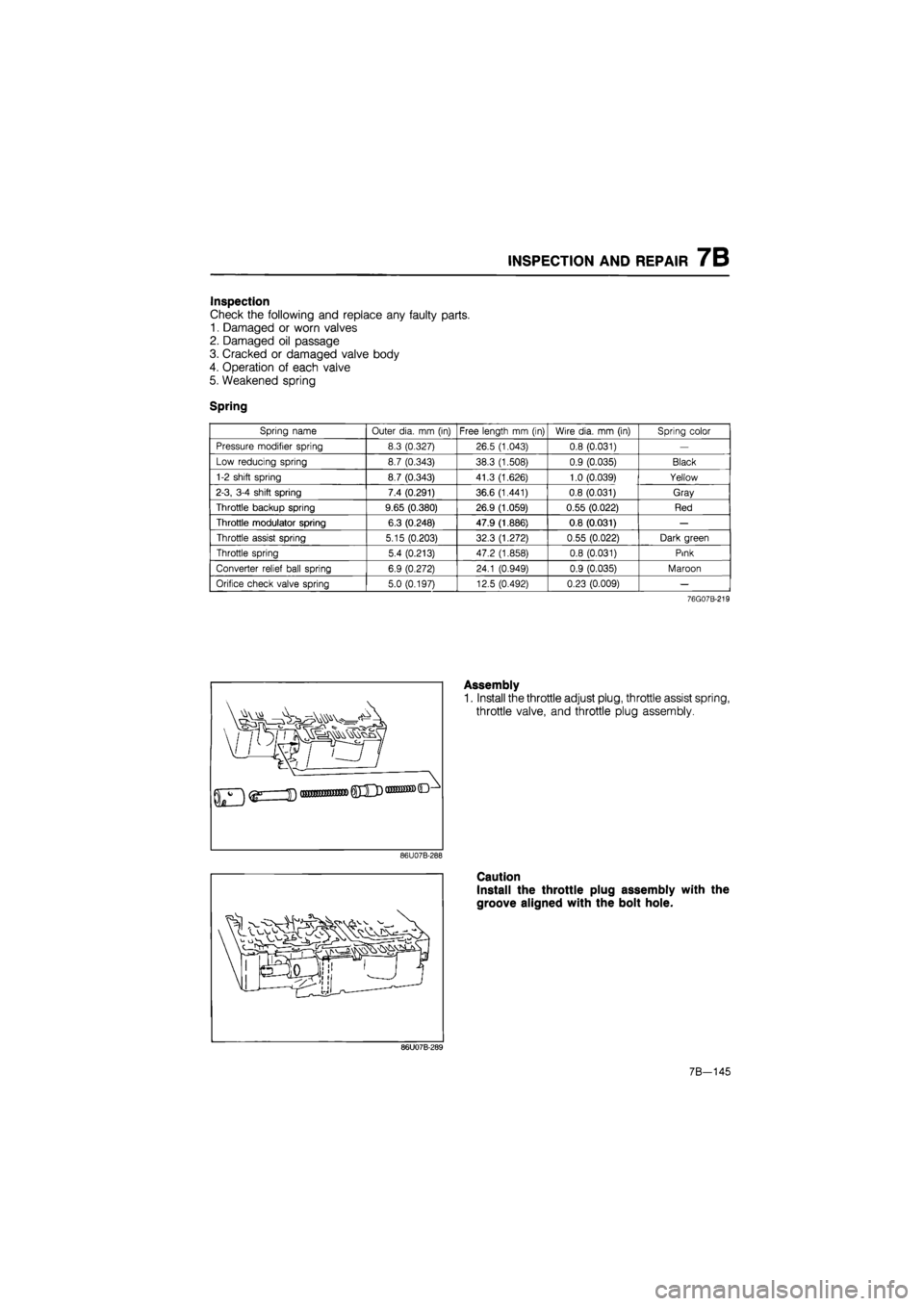
Assembly
1. Install the throttle adjust plug, throttle assist spring,
throttle valve, and throttle plug assembly.
86U07B-288
Caution
Install the throttle plug assembly with the
groove aligned with the bolt hole.
86U07B-289
7B-145
Page 1014 of 1865
7B INSPECTION AND REPAIR
Inspection
Check the following and replace any faulty parts.
1. Damaged or worn valves
2. Damaged oil passage
3. Cracked or damaged valve body
4. Operation of each valve
5. Weakened spring
Spring
Spring name Outer dia.
mm
(in) Free length
mm
(in) Wire dia.
mm (in)
Spring color
Pressure regulator spring 11.5 (0.453) 26.5 (1.043) 1.0 (0.039) Maroon
Lock-up control spring 5.0 (0.197) 35.2 (1.386) 0.6 (0.024) Purple
86U07B-295
Assembly
1. Install the lock-up control spring, lock-up control
valve, stopper plug, and stopper pin.
86U07B-296
Install the pressure regulator valve, pressure regu-
lator spring, pressure regulator spring seat, pres-
sure regulator plug, pressure regulator plug sleeve,
pressure regulator backup plug, stopper plug, and
stopper pin.
Note
Install the stopper plug larger end first.
86U07B-297
3. Install the manual valve.
86U07B-298
7B-148
Page 1035 of 1865

INSPECTION AND REPAIR 7B
Inspection
Check the following and replace any faulty parts.
1. Damaged or worn valves
2. Damaged oil passage
3. Cracked or damaged valve body
4. Operation of each valve
5. Weakened spring
Spring
Spring name Outer dia.
mm (in)
Free length
mm
(in)
30.7 (1.209)
46
2
(1 819)
52
3
(2.059)
Wire dia.
mm (in)
Spring color
Blue
Yellow
Red"
Pressure regulator spring 9.5 (0.374)
Free length
mm
(in)
30.7 (1.209)
46
2
(1 819)
52
3
(2.059)
0.7 (0 028)
0
8
(0.031)
1.0 (0.039)
0.8 (0.031)
Spring color
Blue
Yellow
Red"
Lock-up control spring 7,3 (0 287)
Free length
mm
(in)
30.7 (1.209)
46
2
(1 819)
52
3
(2.059)
0.7 (0 028)
0
8
(0.031)
1.0 (0.039)
0.8 (0.031)
Spring color
Blue
Yellow
Red"
Lock-up support spring 7.0 (0.276)
Free length
mm
(in)
30.7 (1.209)
46
2
(1 819)
52
3
(2.059)
0.7 (0 028)
0
8
(0.031)
1.0 (0.039)
0.8 (0.031)
Spring color
Blue
Yellow
Red" OD lock-up spring 7.1 (0.280) 66.5 (2.618)
0.7 (0 028)
0
8
(0.031)
1.0 (0.039)
0.8 (0.031)
Spring color
Blue
Yellow
Red"
76G07B-166
Assembly
1. Install the lock-up support spring, lock-up support
valve, stopper plug, and stopper pin.
Note
Install the stopper plug large end first.
83U07B-305
2. Install the pressure regulator valve, pressure regu-
lator spring, pressure regulator spring seat, pres-
sure regulator plug, pressure regulator plug sleeve,
pressure regulator backup plug, stopper plug, and
stopper pin.
Note
Install the stopper plug large end first.
83U07B-306
7B—169
Page 1085 of 1865
INSTALLATION 7B
86U07B-453
86U07B-454
76G07B-198
20. Install the tie-rod ends and cotter pins.
Tightening torque:
29—44 N-m (3.0—4.5 m-kg, 22—33 ft-lb)
21. Install the oil cooler outlet and inlet hoses.
22. Install the splash shields.
Tightening torque:
8—11 N-m (80—110 cm-kg, 69—95 in-lb)
23. Install the front wheels.
Tightening torque:
88—118 N-m (9—12 m-kg, 65—87 ft-lb)
24. Connect the throttle cable.
Note
Adjust the throttle cable with the oil pressure
test. (Refer to page 7B—75, 76)
25. Connect the selector cable.
Tightening torque:
Nut
29—39 N-m (3.0—4.0 m-kg, 22—29 ft-lb)
Bolts
16—22 N-m (1.6—2.3 m-kg, 12—17 ft-lb)
26. Connect the ground wires to the transaxle case.
Tightening torque:
8—11 N-m (80—115 cm-kg, 69—99 in-lb)
86U07B-456
7B—219
Page 1087 of 1865
OD
IV) K>
2-4 brake band
—Coasting clutch pressure brake pressure
To oil cooler
N-R accumulator 12-3 accumulator
2-3 Timingr valve 18 Coasting bypass valve Bypass valve Servo control y valve (Blocked)
Pressure modifier valve (Blocked)
3-4 shift valve
Low reducing valve
Pressure regulator valve 3-2 timing valve 3-2 Icapacity valve
Manual valve
Throttle valve
Oil pump
• Throttle pressure
1 Throttle modulated pressure
• Line pressure
I Torque converter pressure Forward clutch pressure\^
Reverse clutch pressure—_____
1-2 accumulator
Throttle back-up valve (Blocked)
-j Throttle J modulator I valve
Apply side 9
Lock-up control valve
-< O
u >
o
o
J3 o
Q >
• m
-< o
3D >
C n
O
O
J3 o
a •C* > • m
-si
CD
Page 1088 of 1865
Apply side 9
Throttle pressure
Throttle modulated pressure
Line pressure
Operating line pressure
1
Torque converter pressure
30 >
Z o m
U)
< O X >
o
o
55
o
0 >
1 m
I Oil pump
Page 1089 of 1865
-vj
ro ro CO
2-4 brake band
Throttle valve
Low and reverse brake pressure [-Coasting clutch pressure|
1-2 accumulator To oil cooler 3r4-Clytch pressure Lock-up control valve
N-R accumulator imulator -3 accumulator
[2-3 Timingf valve Coasting
Bypass valve J Servo control < x ]_ valve (Blocked)
Pressure modifier valve (Blocked)
Throttle modulator valve
Throttle back-up "valve (Blocked) Low reducing valve
Pressure regulator valve 3-2 timing valve 3-2
|
capacity valve
Throttle pressure
Throttle modulated pressure
Line pressure
Torque converter pressure
Forward clutch pressure
Reverse clutch pressure
) Oil pump
Page 1090 of 1865
Apply side 9 Throttle pressure
Throttle modulated pressure
Line pressure
Torque converter pressure
I Oil pump