Page 954 of 1865
7B DISASSEMBLY
DISASSEMBLY
DISASSEMBLY-STEP 1
Components
1. Torque converter
2. Oil pump shaft
3. Oil level gauge and oil filler tube
4. Pulse generator, fluid temperature switch,
and inhibitor switch
5. Solenoid connector
6. Wire harnesses
7. Harness clip
86U07B-116
8. Oil pipes, oil hoses, and switch box
9. Oil pan and gasket
10. Oil strainer and O-ring
11. Control valve body cover and gasket
12. Throttle cable
13. Solenoid connector (Valve body side)
14. Control valve body
15. Oil pump and gasket
7B-88
Page 956 of 1865
7B DISASSEMBLY
4. Assemble the SST.
86U07B-121
5. Lift the transaxle and mount it on the SST.
86U07B-122
Note
Attach the suitable hanger to the oil pump as
shown.
86U07B-123
Warning
Avoid leaning the transaxle to one side dur-
ing disassembly, it may turn quickly and cause
injury.
76U07B-453
7B-90
Page 957 of 1865
DISASSEMBLY 7B
6 G4A-EL
Remove the pulse generator, fluid temperature
switch, and inhibitor switch.
G4A-HL
Remove the inhibitor switch.
76GQ7B-123
7. Disconnect the solenoid connector.
8. Remove the harnesses.
76G07B-124
9. G4A-EL
Remove the harness clip, then remove the oil
pipes, oil hoses and switch box as an assembly.
Note
Remove the ball from the case.
76G07B-125
G4A-HL
Remove the oil pipe.
Note Remove the ball from the case.
76G07B-126
7B—91
Page 958 of 1865
7B DISASSEMBLY
10. Remove the oil pan and gasket.
86U07B-128
86U07B-129
11. Remove the oil strainer and O-ring.
12. Remove the control valve body cover and gasket.
86U07B-130
13. Remove the throttle cable.
(1) Remove the throttle cable attaching bolt and
bracket.
(2) Remove the cable from the throttle cam of the
valve body.
86U07B-131
7B-92
Page 959 of 1865
DISASSEMBLY 7B
14. Pinch the teeth of the solenoid connector and re-
move it by pushing inward.
86U07B-132
15. Remove the control valve body as an assembly.
86U07B-133
16. Remove the oil pump as an assembly.
86U07B-134
7B—93
Page 969 of 1865
DISASSEMBLY 7B
DISASSEMBLY—STEP 4
Component
76G07B-128
1. Governor assembly (G4A-HL)
2. Differential assembly
3. Governor outlet pipe (G4A-HL)
4. Governor inlet pipe (G4A-HL)
5. O-rings (G4A-HL)
6. 2-3 accumulator piston assembly
7. O-rings
8. Roll pin
9. Bearing housing
10. Idle gear assembly
11. Output gear assembly
12. Bearing cover assembly
13. Bearing outer races
14. Adjust shim
15. Oil seals
16. O-rings
17. Converter housing
7B—103
Page 972 of 1865
7B DISASSEMBLY
7. Remove the bearing cover.
(1) Remove the converter housing from the trans-
axle hanger.
(2) Remove the bearing cover bolts.
83U07B-173
8. Remove the bearing outer races.
(1) Press out the bearing outer races with the SST.
Note
Install the bearing outer race during reassem-
bly to adjust the preload.
9. Check the oil seals for damage, replace if
necessary.
10. Check the O-rings for damage, replace if
necessary.
83U07B-174
7B—106
Page 973 of 1865

INSPECTION AND REPAIR 7B
INSPECTION AND REPAIR
PRECAUTION
(1) Several of the parts resemble each other; organize them so that they do not get mixed up.
(2) Clean each part with cleaning oil, clean out the oil holes and oil passages with compressed air,
and check that there are no obstructions.
(3) When using cleaning oil and compressed air, wear protective eyewear.
(4) If a clutch plate or brake band is replaced with a new one, soak it in ATF for 2 hours or more
before installing.
(5) Before assembly, apply ATF to all seal rings, rotating parts, and sliding parts.
(6) All seals, gaskets and roll pins must be replaced with new ones during assembly.
(7) Use petroleum jelly, not grease where required.
(8) When it is necessary to replace a bushing, replace the assembly which includes that bushing.
76G07B-217
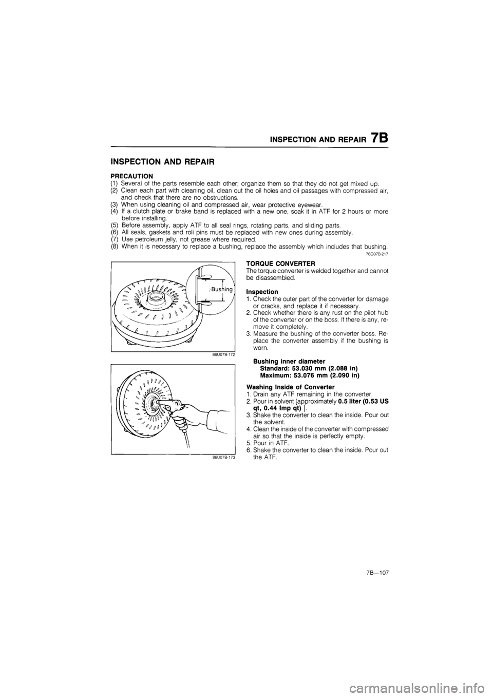
TORQUE CONVERTER
The torque converter is welded together and cannot
be disassembled.
Inspection
1. Check the outer part of the converter for damage
or cracks, and replace it if necessary.
2. Check whether there is any rust on the pilot hub
of the converter or on the boss. If there is any, re-
move it completely.
3. Measure the bushing of the converter boss. Re-
place the converter assembly if the bushing is
worn.
Bushing inner diameter
Standard: 53.030 mm (2.088 in)
Maximum: 53.076 mm (2.090 in)
Washing Inside of Converter
1. Drain any ATF remaining in the converter.
2. Pour in solvent [approximately 0.5 liter (0.53 US
qt, 0.44 Imp qt) ].
3. Shake the converter to clean the inside. Pour out
the solvent.
4. Clean the inside of the converter with compressed
air so that the inside is perfectly empty.
5. Pour in ATF.
6. Shake the converter to clean the inside. Pour out
the ATF.
7B—107