Page 1003 of 1865
INSPECTION AND REPAIR 7B
Components II
Main and rear control body
®
86U07B-266
1. Premain/main rear gasket
2. Main control body
3. Main/rear front gasket
4. Rear separator
5. Main/rear rear gasket
6. Rear control body
7. 3-4 solenoid valve
8. Lock-up solenoid valve
9. Bolts
Disassembly of Control Valve Body
1. Remove the 3-4 solenoid valve and lock-up sole-
noid valve.
2. Remove the O-rings and oil strainers.
86U07B-267
7B—137
Page 1004 of 1865
7B INSPECTION AND REPAIR
3. Remove the 1-2 solenoid valve and 2-3 solenoid
valve and wire harness.
4. Remove the O-rings and oil strainers.
86U07B-268
5. Remove the front indicated bolts and pull out the
front control body with premain separator as a unit.
86U07B-269
86U07B-270
7. Remove the orifice check valve (<£0.8 mm, 0.071
in) and spring from the premain control body.
76G07B-142
7B—138
Page 1008 of 1865

7B INSPECTION AND REPAIR
Inspection
Check the following and replace any faulty parts.
1. Damaged or worn valves
2. Damaged oil passage
3. Cracked or damaged valve body
4. Operation of each valve
5. Weakened spring
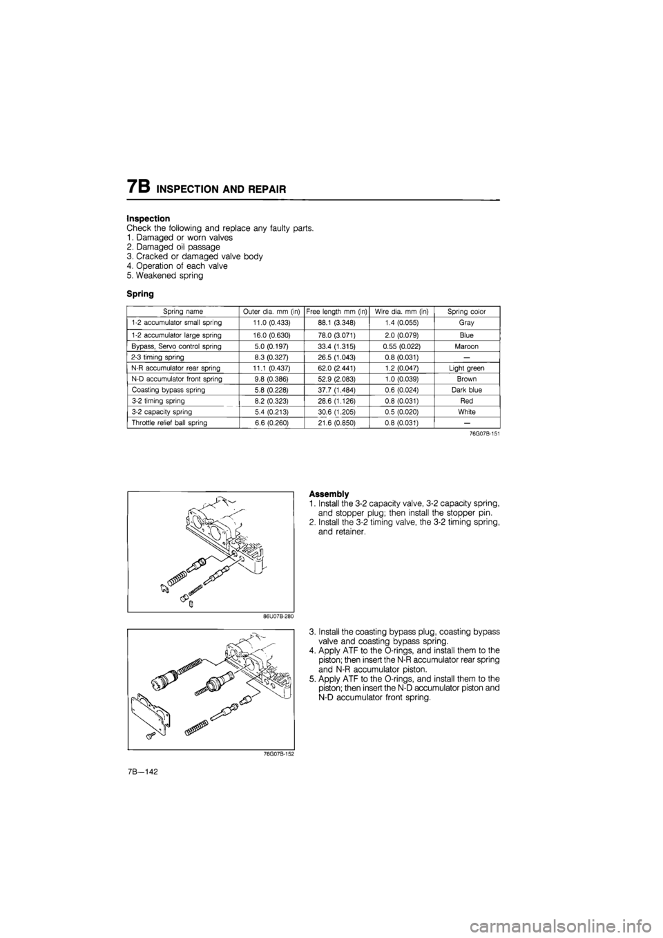
Spring
Spring name Outer dia.
mm
(in) Free length
mm
(in) Wire dia.
mm (in)
Spring color
1-2 accumulator small spring 11.0 (0.433) 88.1 (3.348) 1.4 (0.055) Gray
1-2 accumulator large spring 16.0 (0.630) 78.0 (3.071) 2.0 (0.079) Blue
Bypass, Servo control spring 5.0 (0.197) 33.4 (1.315) 0.55 (0.022) Maroon
2-3 timing spring 8.3 (0.327) 26.5 (1.043) 0.8 (0.031)
—
N-R accumulator rear spring 11.1 (0.437) 62.0 (2.441) 1.2 (0.047) Light green
N-D accumulator front spring 9.8 (0.386) 52.9 (2.083) 1.0 (0.039) Brown
Coasting bypass spring 5.8 (0.228) 37.7 (1.484) 0.6 (0.024) Dark blue
3-2 timing spring 8.2 (0.323) 28.6 (1.126) 0.8 (0.031) Red
3-2 capacity spring 5.4 (0.213) 30.6 (1.205) 0.5 (0.020) White
Throttle relief ball spring 6.6 (0.260) 21.6 (0.850) 0.8 (0.031)
—
76G07B-151
Assembly
1. Install the 3-2 capacity valve, 3-2 capacity spring,
and stopper plug; then install the stopper pin.
2. Install the 3-2 timing valve, the 3-2 timing spring,
and retainer.
86U07B-280
3. Install the coasting bypass plug, coasting bypass
valve and coasting bypass spring.
4. Apply ATF to the O-rings, and install them to the
piston; then insert the N-R accumulator rear spring
and N-R accumulator piston.
5. Apply ATF to the O-rings, and install them to the
piston; then insert the N-D accumulator piston and
N-D accumulator front spring.
76G07B-152
7B—142
Page 1011 of 1865

INSPECTION AND REPAIR 7B
Inspection
Check the following and replace any faulty parts.
1. Damaged or worn valves
2. Damaged oil passage
3. Cracked or damaged valve body
4. Operation of each valve
5. Weakened spring
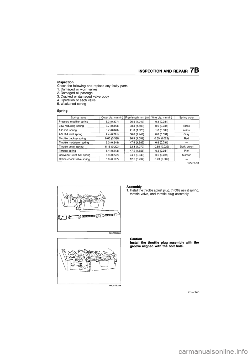
Spring
Spring name Outer dia.
mm
(in) Free length
mm (in)
Wire dia.
mm
(in) Spring color
Pressure modifier spring 8.3 (0.327) 26.5 (1.043) 0.8 (0.031)
—
Low reducing spring 8.7 (0.343) 38.3 (1.508) 0.9 (0.035) Black
1-2 shift spring 8.7 (0.343) 41.3 (1.626) 1.0 (0.039) Yellow
2-3, 3-4 shift spring 7.4 (0.291) 36.6 (1.441) 0.8 (0.031) Gray
Throttle backup spring 9.65 (0.380) 26.9 (1.059) 0.55 (0.022) Red
Throttle modulator spring 6.3 (0.248) 47.9 (1.886) 0.8 (0.031)
—
Throttle assist spring 5.15 (0.203) 32.3 (1.272) 0.55 (0.022) Dark green
Throttle spring 5.4 (0.213) 47.2 (1.858) 0.8 (0.031) Pink
Converter relief ball spring 6.9 (0.272) 24.1 (0.949) 0.9 (0.035) Maroon
Orifice check valve spring 5.0 (0.197) 12.5 (0.492) 0.23 (0.009)
—
76G07B-219
]
Assembly
1. Install the throttle adjust plug, throttle assist spring,
throttle valve, and throttle plug assembly.
86U07B-288
Caution
Install the throttle plug assembly with the
groove aligned with the bolt hole.
86U07B-289
7B-145
Page 1014 of 1865
7B INSPECTION AND REPAIR
Inspection
Check the following and replace any faulty parts.
1. Damaged or worn valves
2. Damaged oil passage
3. Cracked or damaged valve body
4. Operation of each valve
5. Weakened spring
Spring
Spring name Outer dia.
mm
(in) Free length
mm
(in) Wire dia.
mm (in)
Spring color
Pressure regulator spring 11.5 (0.453) 26.5 (1.043) 1.0 (0.039) Maroon
Lock-up control spring 5.0 (0.197) 35.2 (1.386) 0.6 (0.024) Purple
86U07B-295
Assembly
1. Install the lock-up control spring, lock-up control
valve, stopper plug, and stopper pin.
86U07B-296
Install the pressure regulator valve, pressure regu-
lator spring, pressure regulator spring seat, pres-
sure regulator plug, pressure regulator plug sleeve,
pressure regulator backup plug, stopper plug, and
stopper pin.
Note
Install the stopper plug larger end first.
86U07B-297
3. Install the manual valve.
86U07B-298
7B-148
Page 1020 of 1865
7B INSPECTION AND REPAIR
(2) Tighten the rear control body.
Tightening torque:
6—8 N-m (66—80 cm-kg, 57—69 in-lb)
86U07B-319
Install the 3-4 solenoid valve and lock-up solenoid
valve along with new O-rings and oil strainers.
Tightening torque:
6—8 N-m (66—80 cm-kg, 57—69 in-lb)
76G07B-161
18. Install the
1
-2 solenoid valve and 2-3 solenoid valve
along with new O-rings and oil strainers.
Tightening torque:
6—8 N-m (66—80 cm-kg, 57—69 in-lb)
76G07B-162
7B-154
Page 1022 of 1865
7B INSPECTION AND REPAIR
Components II
Main and rear control body
1. Premain/main rear gasket
2. Main control body
3. Main/rear front gasket
4. Rear separator
5. Main/rear rear gasket
6. Rear control body
83U07B-274
Disassembly of Control Valve Body
1. Remove the lock-up solenoid valve.
2. Remove the O-ring and oil strainer.
83U07B-275
7B-156
Page 1025 of 1865
INSPECTION AND REPAIR 7B
13. Remove the orifice check valves (01.5 mm, 0.059
in) and springs, oil strainer, and rubber ball from
the main control body.
76G07B-164
7B-159