Page 1439 of 1865

REAR DISC BRAKE 1 1
REAR DISC BRAKE
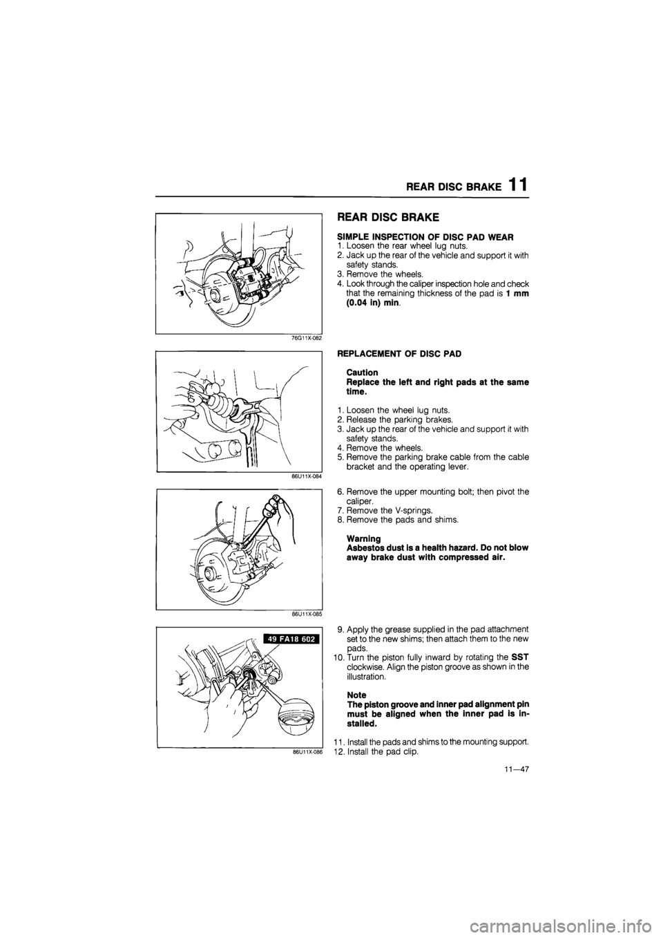
SIMPLE INSPECTION OF DISC PAD WEAR
1. Loosen the rear wheel lug nuts.
2. Jack up the rear of the vehicle and support it with
safety stands.
3. Remove the wheels.
4. Look through the caliper inspection hole and check
that the remaining thickness of the pad is 1 mm
(0.04 in) min.
76G11X-082
86U11X-084
REPLACEMENT OF DISC PAD
Caution
Replace the left and right pads at the same
time.
1. Loosen the wheel lug nuts.
2. Release the parking brakes.
3. Jack up the rear of the vehicle and support it with
safety stands.
4. Remove the wheels.
5. Remove the parking brake cable from the cable
bracket and the operating lever.
6. Remove the upper mounting bolt; then pivot the
caliper.
7. Remove the V-springs.
8. Remove the pads and shims.
Warning
Asbestos dust is a health hazard. Do not blow
away brake dust with compressed air.
86U11X-085
86U11X-086
9. Apply the grease supplied in the pad attachment
set to the new shims; then attach them to the new
pads.
10. Turn the piston fully inward by rotating the SST
clockwise. Align the piston groove as shown in the
illustration.
Note
The piston groove and inner pad alignment pin
must be aligned when the inner pad is in-
stalled.
11. Install the pads and shims to the mounting support.
12. Install the pad clip.
11—47
Page 1442 of 1865
1 1 REAR DISC BRAKE
DISASSEMBLY AND ASSEMBLY
1. Disassemble the caliper in the sequence shown in the figure, referring to disassembly note for spe-
cially marked parts.
2. Inspect all parts, referring to inspection note.
3. Assemble in the reverse order of disassembly, referring to assembly note for specially marked parts.
76G11X-0B5
1. Guide pin
2. Pin boot
3. Bushing
4. Retaining ring
5. Dust seal
6. Piston
7. Piston seal
8. Snap ring
9. Adjuster spindle
10. Stopper
11. O-ring
12. Connecting link
13. Return spring
14. Operating lever
15. Boot
16. Boot clip
17. Needle bearing
18. Cable braket
Disassembly Note
Piston
Remove the piston with the SST.
Note
The piston can be removed by turning the SST
counterclockwise.
86U11X-092
11-50
Page 1445 of 1865
REAR DISC BRAKE 1 1
86U11X-101
4. Move the operating lever and check that the ad-
juster spindle moves smoothly.
Piston
1. Clean the piston.
2. Install the dust seal in the piston groove.
3. Turn the piston into the caliper cylinder while rotat-
ing the SST clockwise.
Note
Turn the piston in fully, and align the piston
grooves as shown in the illustration.
4. Fit the dust seal into the caliper cylinder.
87U11X-102
11—53
Page 1549 of 1865

13 REAR WHEEL ALIGNMENT
76G13X-033
86U13X-116
86U13X-117
86U13X-116
13-52
REAR WHEEL ALIGNMENT
PRE-INSPECTION
1. Check the tire inflation and bring to the recom-
mended pressure.
2. Inspect the wheel and tire runout.
3. The vehicle must be on level ground and have no
luggage or passenger load.
4. Check that the suspension is correctly adjusted.
5. The difference in height between the left and right
sides from the center of the wheel to the fender
rim should be within 10 mm (0.39 in).
Caution
a) Front and rear wheel alignments should be
checked simultaneously. If adjustment is
made to either the front or rear wheels,
recheck the alignment, particularly toe-in,
on all other wheels.
b) Check and adjust the steering angle trans-
fer shaft after adjusting the rear wheel align-
ment. (Refer to Section 10.)
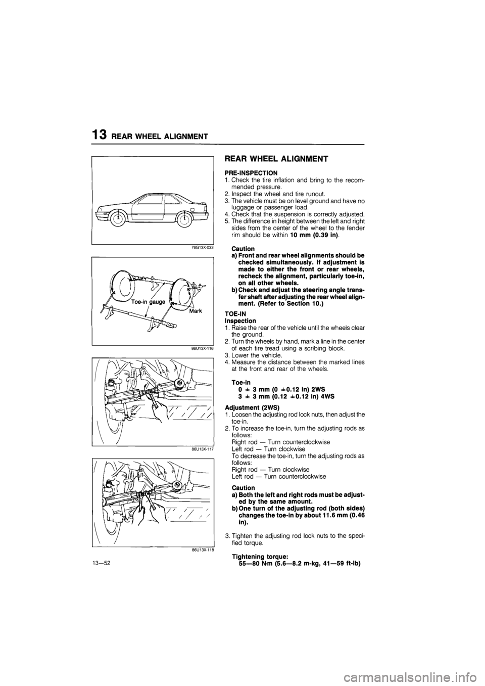
TOE-IN
Inspection
1. Raise the rear of the vehicle until the wheels clear
the ground.
2. Turn the wheels by hand, mark a line in the center
of each tire tread using a scribing block.
3. Lower the vehicle.
4. Measure the distance between the marked lines
at the front and rear of the wheels.
Toe-in
0 ± 3 mm (0 ±0.12 in) 2WS
3 ± 3 mm (0.12 ±0.12 in) 4WS
Adjustment (2WS)
1. Loosen the adjusting rod lock nuts, then adjust the
toe-in.
2. To increase the toe-in, turn the adjusting rods as
follows:
Right rod — Turn counterclockwise
Left rod — Turn clockwise
To decrease the toe-in, turn the adjusting rods as
follows:
Right rod — Turn clockwise
Left rod — Turn counterclockwise
Caution
a) Both the left and right rods must be adjust-
ed by the same amount.
b) One turn of the adjusting rod (both sides)
changes the toe-in by about 11.6 mm (0.46
in).
3. Tighten the adjusting rod lock nuts to the speci-
fied torque.
Tightening torque:
55—80 N-m (5.6—8.2 m-kg, 41—59 ft-lb)
Page 1672 of 1865
CLUSTER SWITCH 15
CLUSTER SWITCH
STRUCTURAL VIEW
For Left Hand Drive
Rocker type
-A
M
Except
ECE
Rear def. SW
Push type
-<3»-
ivi
a
Rear
wiper
SW
Rear +washer SW
Digital clock
' Oscillator SW
Hazard SW
A
Digital clock
/ Oscillator SW ./ i
A
Hazard SW
Rear def.
SW
ECE only
lot
4 Hazard
SW
Rear fog
light
SW
76G15X-003
15—17
Page 1793 of 1865

16 OUTLINE
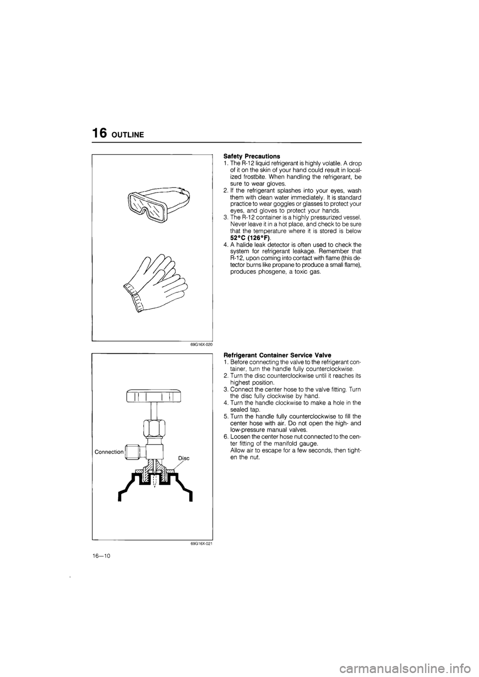
Safety Precautions
1. The R-12 liquid refrigerant is highly volatile. A drop
of it on the skin of your hand could result in local-
ized frostbite. When handling the refrigerant, be
sure to wear gloves.
2. If the refrigerant splashes into your eyes, wash
them with clean water immediately. It is standard
practice to wear goggles or glasses to protect your
eyes, and gloves to protect your hands.
3. The R-12 container is a highly pressurized vessel.
Never leave it in a hot place, and check to be sure
that the temperature where it is stored is below
52°C (126°F).
4. A halide leak detector is often used to check the
system for refrigerant leakage. Remember that
R-12, upon coming into contact with flame (this de-
tector burns like propane to produce a small flame),
produces phosgene, a toxic gas.
69G16X020
V/^V
Connection
LZl
jvmi
Refrigerant Container Service Valve
1. Before connecting the valve to the refrigerant con-
tainer, turn the handle fully counterclockwise.
2. Turn the disc counterclockwise until it reaches its
highest position.
3. Connect the center hose to the valve fitting. Turn
the disc fully clockwise by hand.
4. Turn the handle clockwise to make a hole in the
sealed tap.
5. Turn the handle fully counterclockwise to fill the
center hose with air. Do not open the high- and
low-pressure manual valves.
6. Loosen the center hose nut connected to the cen-
ter fitting of the manifold gauge.
Allow air to escape for a few seconds, then tight-
en the nut.
69G16X-021
16-10