Page 990 of 1865
7B INSPECTION AND REPAIR
86U07B-228
86U07B-229
86U07B-230
7. Install the one-way clutch inner race into the one-
way clutch outer race by turning inner race coun-
terclockwise.
8. Hold the one-way clutch outer race. Check that the
inner race turns only counterclockwise.
Assembly
1. Install the small sun gear into the sun gear drum.
2. Install the snap ring.
3. Apply petroleum jelly to the thrust bearing to se-
cure it; then install it to the one-way clutch inner
race.
Thrust bearing outer diameter:
62.1 mm (2.44 in)
4. Install the one-way clutch inner and outer race to
the sun gear drum.
Note
Align the splines of the one-way clutch inner
race and small sun gear clutch hub.
86U07B-231
7B—124
Page 991 of 1865
INSPECTION AND REPAIR 7B
5. Install the snap ring.
86U07B-232
86U07B-233
6. Check that when the small sun gear is held, the
one-way clutch outer race turns smoothly and only
clockwise.
7. Apply petroleum jelly to the thrust bearing to se-
cure it; then install it to the sun gear drum.
Thrust bearing outer diameter:
72.0 mm (2.83 in)
86U07B-234
7B—125
Page 993 of 1865
INSPECTION AND REPAIR 7B
One-way clutch 6. Damaged or worn one-way clutch and operation
7. Detached roller
Note
Assemble the one-way clutch and the inner
race, then confirm that the one-way clutch ro-
tates only clockwise and smoothly.
86U07B-238
Assembly
1. Assemble the carrier hub assembly to the inner
race.
86U07B-239
2. Install th snap ring.
86U07B-240
3. Apply petroleum jelly to the bearing races to se-
cure them; then install them to both sides of the
one-way clutch and carrier hub assembly.
Bearing race outer diameter
Sun gear drum side: 72.0 mm (2.83 in)
3-4 clutch side: 57.0 mm (2.21 in)
Note
Install the tabs of the bearing race into the
alignment holes.
86U07B-241
7B—127
Page 1071 of 1865
ASSEMBLY 7B
11. Install the one-way clutch.
(1) Hold the one-way clutch horizontally.
(2) Install it by turning the carrier hub assembly
counterclockwise.
(3) Install the snap ring.
86U07B-406
49 G019 028
12. Install the servo to the transaxle case.
(1) Install the servo spring and servo.
(2) Compress the servo with the SST.
(3) Install the snap ring.
(4) Remove the SST.
(5) Install the piston stem.
86U07B-407
13. Install the anchor strut.
86U07B-408
14. Install the 2-4 brake band in the transaxle case so
that it is expanded fully.
Note
Interlock the 2-4 brake band and anchor strut
as shown.
86U07B-409
7B-205
Page 1138 of 1865
7C ELECTRIC COMPONENTS
Adjustment
1. Loosen the kick-down switch locknuts.
2. Depress the accelerator pedal fully.
3. Turn the switch until the threaded case touches the
stop.
4. Turn the switch counterclockwise one-half turn.
5. Secure the switch with the locknut.
76G07C-039
KICK-DOWN SOLENOID
Check that the rod extends when 12 V is applied.
76G07C-040
7C-24
Page 1162 of 1865
7C DISASSEMBLY
76G07C-110
76G07C-111
76G07C-112
7. Remove the retaining plate, drive plate, driven
plate, and dished plate.
8. Remove the low and reverse brake hub.
(1) Install the SST to the low and reverse brake
hub as shown.
(2) Compress the brake hub.
(3) Remove the snap ring.
(4) Remove the SST.
(5) Remove the low and reverse brake hub and
springs.
9. Remove the low and reverse brake piston.
(1) Install the SST to the low and reverse brake
piston as shown.
(2) Remove the brake piston by turning the SST
counterclockwise.
76G07C-113
7C—48
Page 1423 of 1865

POWER BRAKE UNIT 1 1
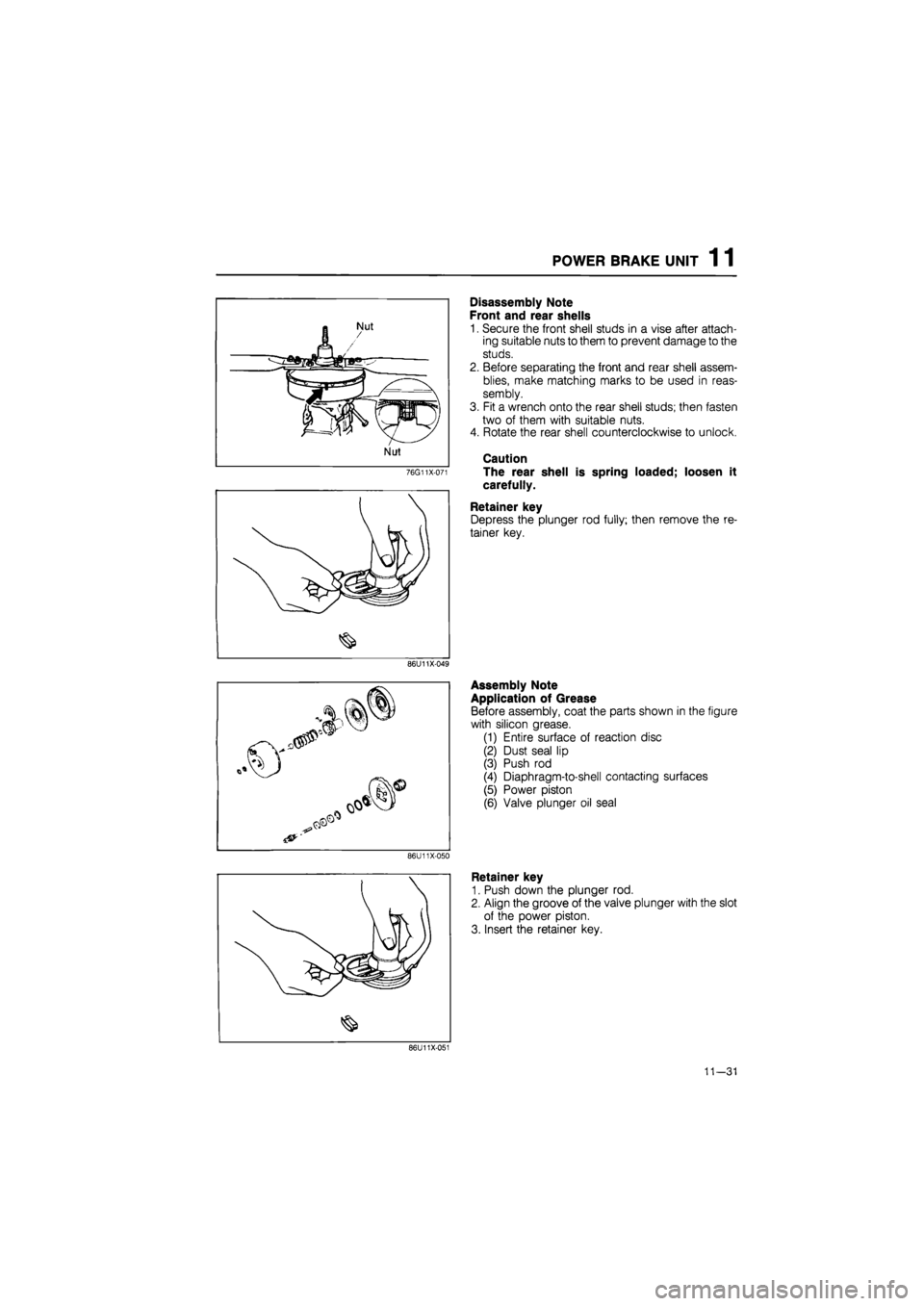
76G11X-071
Disassembly Note
Front and rear shells
1. Secure the front shell studs in a vise after attach-
ing suitable nuts to them to prevent damage to the
studs.
2. Before separating the front and rear shell assem-
blies, make matching marks to be used in reas-
sembly.
3. Fit a wrench onto the rear shell studs; then fasten
two of them with suitable nuts.
4. Rotate the rear shell counterclockwise to unlock.
Caution
The rear shell is spring loaded; loosen it
carefully.
Retainer key
Depress the plunger rod fully; then remove the re-
tainer key.
86U11X-049
86U11X-050
Assembly Note
Application of Grease
Before assembly, coat the parts shown in the figure
with silicon grease.
(1) Entire surface of reaction disc
(2) Dust seal lip
(3) Push rod
(4) Diaphragm-to-shell contacting surfaces
(5) Power piston
(6) Valve plunger oil seal
Retainer key
1. Push down the plunger rod.
2. Align the groove of the valve plunger with the slot
of the power piston.
3. Insert the retainer key.
86U11X-051
11—31
Page 1424 of 1865

1 1 POWER BRAKE UNIT
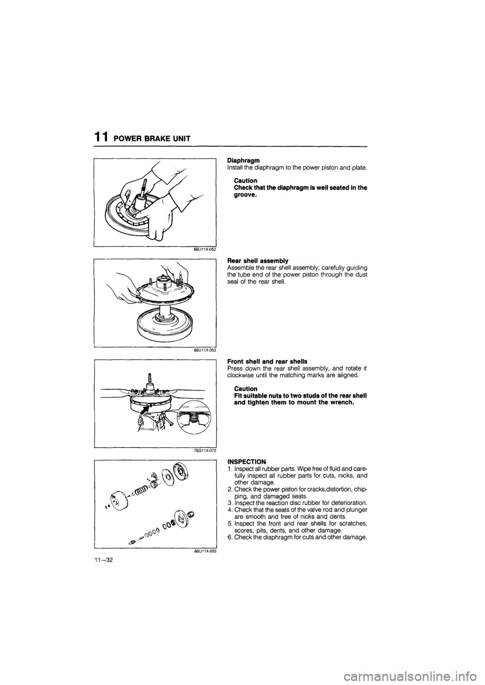
Diaphragm
Install the diaphragm to the power piston and plate.
Caution
Check that the diaphragm is well seated in the
groove.
86U11X-052
Rear shell assembly
Assemble the rear shell assembly; carefully guiding
the tube end of the power piston through the dust
seal of the rear shell.
86U11X-053
Front shell and rear shells
Press down the rear shell assembly, and rotate it
clockwise until the matching marks are aligned.
Caution
Fit suitable nuts to two studs of the rear shell
and tighten them to mount the wrench.
76G11X-072
INSPECTION
1. Inspect all rubber parts. Wipe free of fluid and care-
fully inspect all rubber parts for cuts, nicks, and
other damage.
2. Check the power piston for cracks,distortion, chip-
ping, and damaged seats.
3. Inspect the reaction disc rubber for deterioration.
4. Check that the seats of the valve rod and plunger
are smooth and free of nicks and dents.
5. Inspect the front and rear shells for scratches,
scores, pits, dents, and other damage.
6. Check the diaphragm for cuts and other damage.
11—32