Page 719 of 1865
DISTRIBUTOR 5
FE West Germany (MTX)
24c
14<
0 0) O)
a>
®
O) c a> ^
I 0 1.76° 3.36° 5.32°
Engine Speed (rpm)
FE 12 valve (Carb.)
© ©
118°
12° O) c (0
c CO
6 o 1,200 2,400 4,0005,000
Engine Speed (rpm)
FE West Germany (ATX)
oT
24' 0) a> © "D
© O) c CO JX c CO
14c
6 0 1,300 3,350 5,320
Engine Speed (rpm)
EF EGI a) ©
O) a> ©
o> c ©
C CO
O
18°
12°
1,000 2,600 4,600 5,800
Engine Speed (rpm)
F6, F8 © ©
O) © tj, ©
cn
« 8°
c a)
6 o
86U05X-054
100 (3.94) 300 (11.81)
mmHg (inHg)
Vacuum Advance
1. Warm up the engine to the normal operating tem-
perature.
2. Check that the idle speed and ignition timing are
correct.
3. Disconnect the vacuum hoses from the vacuum
control unit, and plug them.
4. Connect a vacuum pump to the vacuum control
unit.
5. Apply vacuum and check the advance with the tim-
ing light.
86U05X-055
5—13
Page 729 of 1865
ALTERNATOR 5
TROUBLESHOOTING
Preliminary Check
1. Turn the ignition switch ON, and check that
the alternator warning light illuminates.
2. Start the engine, and check that the alternator warning light goes off.
76G05X-024
1. Alternator warning light always not illuminate
76G05X-025
2. Alternator warning light illuminates when engine running
76G05X-026
5-23
Page 731 of 1865
ALTERNATOR 5
Warning
Disconnect the nagative battery terminal when disconnect or reconnect B terminal.
TEST 1
1. Disconnect the alternator connector (2-pin).
2. Connect the SST.
4. Connect the red clip of the adapter harness to the battery
(
+
),
and check that the red
lamp and green lamp illuminate.
5. Start the engine and check that both lamps go off.
86U05X-010
TEST 2
1. Connect an ammeter (75A min.) between the wire and the B terminal.
2. Turn all headlights and accessories on, and depress the brake pedal.
3. Start the engine and check that output current is 70A (RF-CX: 75A) or more at
2,500—3,000 rpm of the engine speed.
Caution
Do not ground the B terminal.
76G05X-029
B terminal
5-25
Page 936 of 1865

7B ELECTRICAL SYSTEM COMPONENTS
Terminal Connected to Voltage Condition
1J — — —
1K — — —
1L (Input) Idle switch Below 1.5V At idle 1L (Input) Idle switch Approx. 12V Other speeds
1M — — —
1N (Input) Brake light switch Approx. 12V Brake pedal depressed 1N (Input) Brake light switch Below 1.5V Brake pedal released
10 (Input) Throttle sensor
Approx. 5V Ignition switch ON 10 (Input) Throttle sensor Below 1,5V Ignition switch OFF
1P (Input)
Throttle sensor
Approx. 0.5—4.3V Throttle valve fully closed to fully open
1Q (Input) Vehicle speed sensor
Approx. 4.5V During driving
1Q (Input) Vehicle speed sensor Approx. 4.5V or below 1.5V Vehicle stopped
1R (Ground) Throttle sensor Below 1,5V —
1S (Input) Pulse generator Approx. 12V Engine running 1S (Input) Pulse generator Below 1,5V Engine stopped
1S (Ground) Pluse generator Below 1.5V —
2A (Battery power) Battery Approx. 12V Ignition switch ON 2A (Battery power) Battery Below 1,5V Ignition switch OFF
2B (Ground) Body ground Below 1,5V —
2C (Memory power) Battery Approx. 12V —
2D (Ground) Body ground Below 1,5V —
2E (Output) 1-2 shift solenoid valve Approx. 12V
Refer to page 7B—26 of solenoid valve
operation table
2E (Output) 1-2 shift solenoid valve Below 1.5V Refer to page 7B—26 of solenoid valve
operation table
2F (Output) 2-3 shift solenoid valve Approx. 12V
Refer to page 7B—26 of solenoid valve
operation table
2F (Output) 2-3 shift solenoid valve Below 1,5V
Refer to page 7B—26 of solenoid valve
operation table
2G — — —
2H (Output) 3-4 shift solenoid valve Approx. 12V Refer to page 7B—26 of solenoid valve operation table 2H (Output) 3-4 shift solenoid valve Below 1.5V
Refer to page 7B—26 of solenoid valve operation table
21 — — —
2J (Output) Lock-up solenoid valve Approx. 12V Lock-up 2J (Output) Lock-up solenoid valve Below 1,5V Other
2K (Output) Hold indicator Below 1,5V Hold mode 2K (Output) Hold indicator Approx. 12V Other modes
2L (Output) Mode indicator Approx. 12V Hold mode 2L (Output) Mode indicator Below 1,5V Power or economy mode
2M (Output) EC-AT Tester
(malfunction code)
Approx. 12V Normal
2M (Output) EC-AT Tester
(malfunction code) Below 1,5V If malfunction present 2M (Output) EC-AT Tester
(malfunction code) Code signal Self-diagnosis check connector grounded
2N — — —
20 (Input) Fluid temperature switch Below 1,5V Above 150°C (302°F) 20 (Input) Fluid temperature switch Approx. 10—12V Below 143°C (289°F)
2P (Input) EC-AT check connect Approx. 12V —
76G07B-084
7B-70
Page 1027 of 1865

INSPECTION AND REPAIR 7B
Inspection
Check the following and replace any faulty parts.
1. Damaged or worn valves
2. Damaged oil passage
3. Cracked or damaged valve body
4. Operation of each valve
5. Weakened spring
Spring
Spring name Outer dia.
mm
(in) Free length
mm (in)
Wire dia.
mm
(in) Spring color
1-2 accumulator small spring F8 engine 9.9 (0.400) 84.7 (3.335) 1.2 (0.047) Red
1-2 accumulator large spring
FE engine 13.0 (0.512) 73.2 (2.881) 1.8 (0.071) Pink 1-2 accumulator large spring F8 engine 16.0 (0.630) 84.7 (3.335) 2.0 (0.079) White
Bypass spring 5.0 (0.197) 25.1 (0.988) 0.7 (0.028) Yellow
Servo control spring 4.9 (0.193) 27.1 (1.067) 0.5 (0.020) Light blue
2-3 timing spring 8.3 (0.327) 26.5 (1.043) 0.8 (0.031)
—
N-R accumulator rear spring 11.1 (0.437) 68.2 (2.685) 1.0 (0.039) Blue
N-D accumulator front spring 9.8 (0.386) 60.9 (2.398) 1.1 (0.043) Yellow
Low reducing spring 8.7 (0.343) 38.3 (1.508) 0.9 (0.035) Black
OD release spring 6.0 (0.236) 32.6 (1.283) 0.6 (0.024) Orange
Coasting bypass spring 5.8 (0.228) 31.3 (1.232) 0.6 (0.024) Yellow
3-2 timing spring 8.2 (0.323) 28.55 (1.124) 0.8 (0.031) Maroon
3-2 capacity spring 5.55 (0.219) 30.5 (1.201) 0.55 (0.022) Light green
Throttle relief ball spring 6.6 (0.260) 20.3 (0.799) 0.8 (0.031) Light green
76G07B-165
Assembly
1. Install the 3-2 capacity valve, 3-2 capacity spring,
stopper plug, and stopper pin.
2. Install the 3-2 timing valve, 3-2 timing spring, and
retainer.
83U07B-287
3. Install the coasting bypass plug, coasting bypass
valve, and coasting bypass spring.
4. Apply ATF to the O-rings, and install them onto the
piston; then insert the N-R accumulator rear spring,
and N-R accumulator piston.
5. Apply ATF to the O-rings, and install them onto the
piston; then insert the N-D accumulator piston, and
N-D accumulator front spring.
83U07B-288
7B—161
Page 1137 of 1865

ELECTRIC COMPONENTS 7C
76G07C-036
76G07C-037
76G07C-038
ELECTRIC COMPONENTS
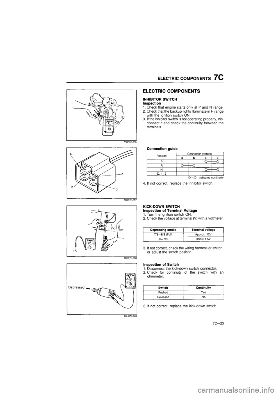
INHIBITOR SWITCH
Inspection
1. Check that engine starts only at P and N range.
2. Check that the backup lights illuminate in R range
with the ignition switch ON.
3. If the inhibitor switch is not operating properly, dis-
connect it and check the continuity between the
terminals.
Connection guide
Position
N
D, 1, 2
Connector terminal
-O
O -O
-O
O—O: Indicates continuity
4. If not correct, replace the inhibitor switch.
KICK-DOWN SWITCH
Inspection of Terminal Voltage
1. Turn the ignition switch ON.
2. Check the voltage at terminal (V) with a voltmeter.
Depressing stroke Terminal voltage
7/8-8/8 (Full) Approx. 12 V
0-7/8 Below 1,5V
3. If not correct, check the wiring harness or switch,
or adjust the switch position.
Inspection of Switch
1. Disconnect the kick-down switch connector.
2. Check for continuity of the switch with an
ohmmeter.
Switch Continuity
Pushed Yes
Released No
3. If not correct, replace the kick-down switch.
83U07B-060
7C—23
Page 1322 of 1865
1 0 4-WHEEL STEERING GEAR AND LINKAGE
(Example) ^"in)
-I
8 mm (0.31 in)
1 1111111
- ^Center
10 mm (0.39 in)
86U10X-309
(8) The center position can be determined from
the left/right measurements in (5) and (7) above.
Example:
Right rotation.... 10 mm (0.39 in)
Left rotation....8 mm (0.31 in)
Center = Right 1 mm (0.04 in)
(9) Check that the center is within specification.
Specification
= R 5 mm (0.4 in ) to L 5 mm (0.4 in)
(10) If not correct, adjust the steering angle trans-
fer shaft.
2. Steering Inspection
With the vehicle stopped and the engine running,
check that the rear wheels turn in the opposite
direction when the steering wheel is turned and that
there is no abnormal noise.
86U10X-310
3.4WS Electric System Inspection
Drive the vehicle and check that the 4WS warning
light does not come on at over 40 km/h (25mph).
86U10X-311
10—34
Page 1376 of 1865

1 0 ELECTRICAL COMPONENTS OF ELECTRONICALLY-CONTROLLED POWER STEERING (ECPS)
76G10X-020
76G10X-021
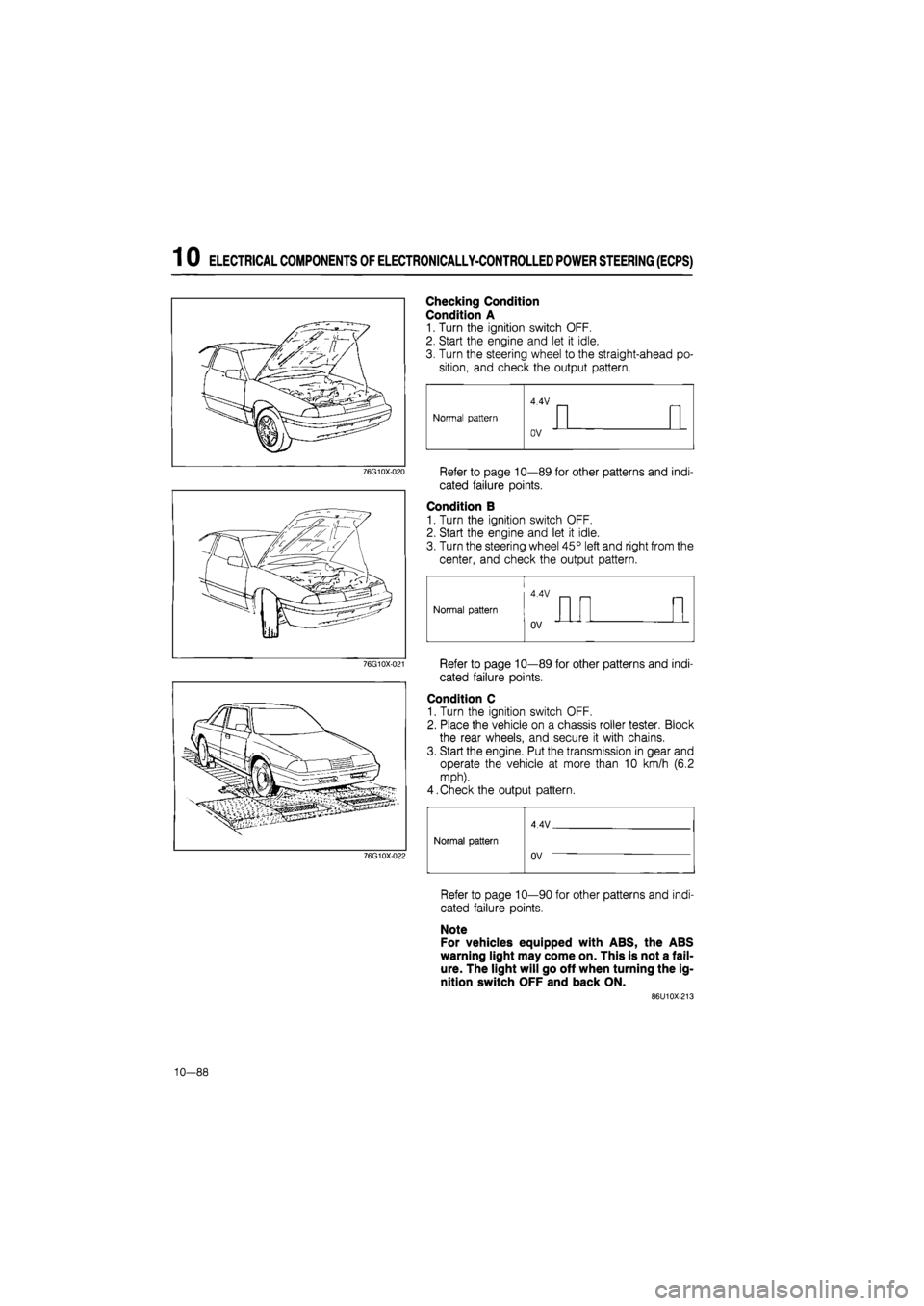
Checking Condition
Condition A
1. Turn the ignition switch OFF.
2. Start the engine and let it idle.
3. Turn the steering wheel to the straight-ahead po-
sition, and check the output pattern.
Refer to page 10—89 for other patterns and indi-
cated failure points.
Condition B
1. Turn the ignition switch OFF.
2. Start the engine and let it idle.
3. Turn the steering wheel 45° left and right from the
center, and check the output pattern.
Refer to page 10—89 for other patterns and indi-
cated failure points.
Condition C
1. Turn the ignition switch OFF.
2. Place the vehicle on a chassis roller tester. Block
the rear wheels, and secure it with chains.
3. Start the engine. Put the transmission in gear and
operate the vehicle at more than 10 km/h (6.2
mph).
4.Check the output pattern.
76G10X-022
Normal pattern
4 4V
Normal pattern Normal pattern
uV
Refer to page 10—90 for other patterns and indi-
cated failure points.
Note
For vehicles equipped with ABS, the ABS
warning light may come on. This is not a fail-
ure. The light will go off when turning the ig-
nition switch OFF and back ON.
86U10X-213
10—88