Page 1740 of 1865

CRUISE CONTROL SYSTEM 1 5
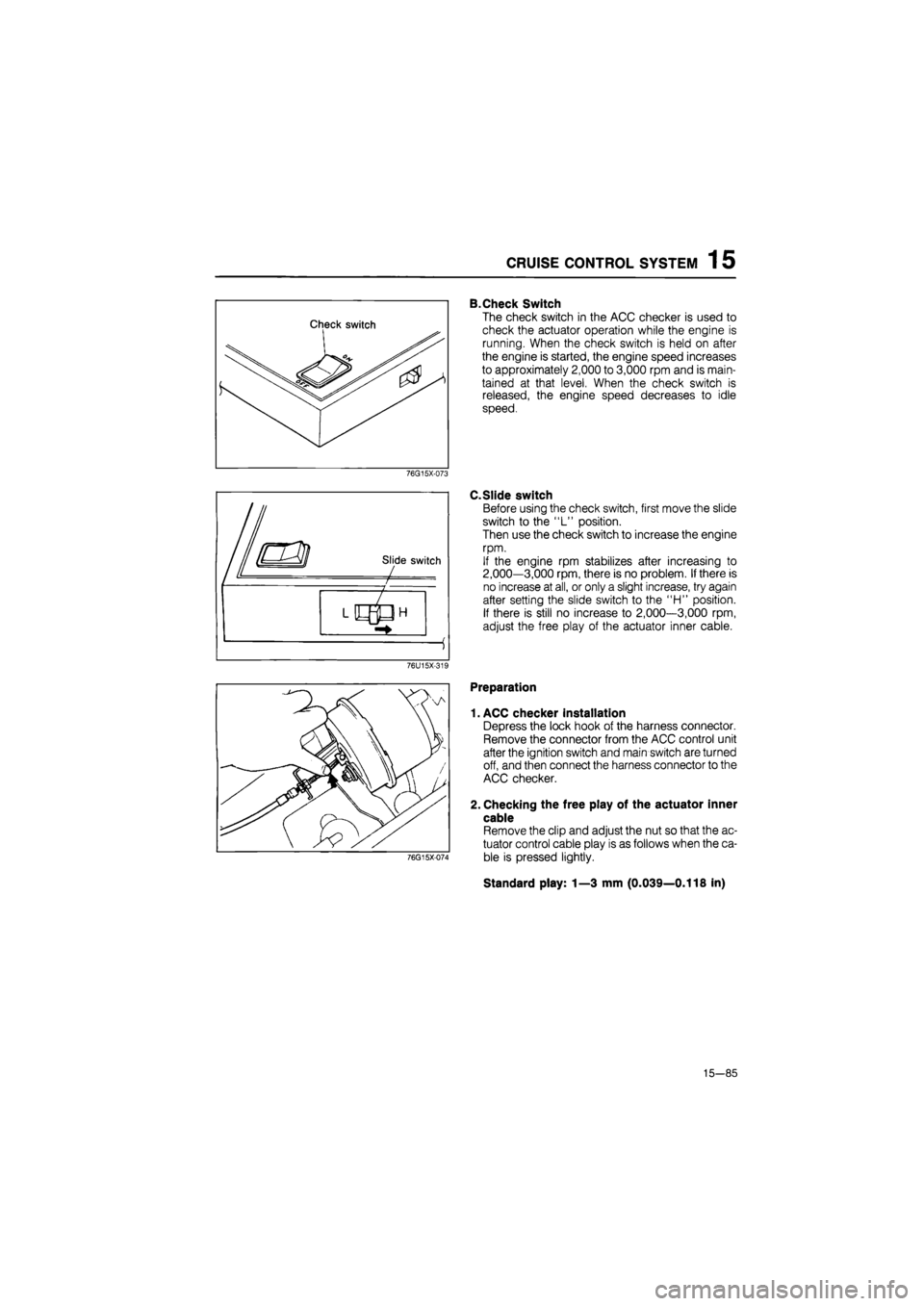
B.Check Switch
The check switch in the ACC checker is used to
check the actuator operation while the engine is
running. When the check switch is held on after
the engine is started, the engine speed increases
to approximately 2,000 to 3,000 rpm and is main-
tained at that level. When the check switch is
released, the engine speed decreases to idle
speed.
76G15X-073
C.Slide switch
Before using the check switch, first move the slide
switch to the "L" position.
Then use the check switch to increase the engine
rpm.
If the engine rpm stabilizes after increasing to
2,000—3,000 rpm, there is no problem. If there is
no increase at all, or only a slight increase, try again
after setting the slide switch to the "H" position.
If there is still no increase to 2,000—3,000 rpm,
adjust the free play of the actuator inner cable.
76U15X-319
76G15X-074
Preparation
1. ACC checker installation
Depress the lock hook of the harness connector.
Remove the connector from the ACC control unit
after the ignition switch and main switch are turned
off, and then connect the harness connector to the
ACC checker.
2. Checking the free play of the actuator inner
cable
Remove the clip and adjust the nut so that the ac-
tuator control cable play is as follows when the ca-
ble is pressed lightly.
Standard play: 1—3 mm (0.039—0.118 in)
15—85
Page 1742 of 1865

CRUISE CONTROL SYSTEM 1 5
CHECK LIGHTS (correct response)
ACTUATOR £
5 (O
W X
CHECK ITEMS AND CONDITIONS £ <0 z
VAC
CM I-1-z
Ul * < IE ffl X o V-
z o F < z ta
DC O 1-< DC Ui
TROUBLESHOOTING
(INCORRECT RESPONSE)
< S VAC UJ > < > -1 o o o UJ O
8. START THE ENGINE
• Shift lever to "N" position (A/T) O O O o X
A/T
O M/T X
O or X —
9. ACTUATOR OPERATION: (EGI model only) • After engine is started, set the slide switch "L" or "H". Then turn on check switch (keep in "D" position) Note: Engine speed should in-crease to 2,000—3,000 rpm. If over 4,000 rpm release the switch immediately.
o
X
1
o
X X X
A/T O M/T X
O or X
If engine speed does not come up to and remain
in
the
2,000
to
3,000
rpm. range, check the actuator and as-sociated harness.
10. SPEED SENSOR OUTPUT
Keeping idling condition, drive ve-
hicle slowly. o o 0 o X X 0 1 X
If GENERATOR LIGHT does not flash, trouble may be with speed sensor and associated harness.
76U15X-199
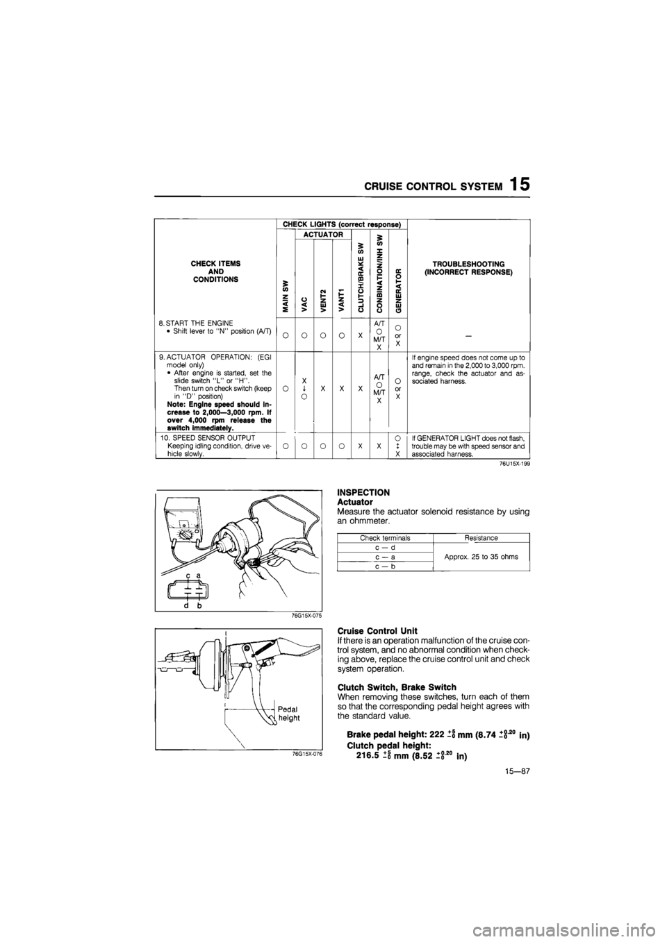
INSPECTION
Actuator
Measure the actuator solenoid resistance by using
an ohmmeter.
Check terminals Resistance
c-d
Approx. 25 to 35 ohms c — a Approx. 25 to 35 ohms
c — b
Approx. 25 to 35 ohms
76G15X-075
Cruise Control Unit
If there is an operation malfunction of the cruise con-
trol system, and no abnormal condition when check-
ing above, replace the cruise control unit and check
system operation.
Clutch Switch, Brake Switch
When removing these switches, turn each of them
so that the corresponding pedal height agrees with
the standard value.
76G15X-076
Brake pedal height: 222 ±1 mm (8.74 1820
Clutch pedal height:
216.5 ±8 mm (8.52 ±820 In)
in)
15-87
Page 1749 of 1865

1 5 AUTO ADJUSTING SUSPENSION (AAS)
AUTO ADJUSTING SUSPENSION (AAS)
CIRCUIT DIAGRAM
Combination switch iq Speed sensor
M
Panel light
control
AAS control unit
Steering angle sensor
H
N
Check connector
IG IG
Actuator (RR)
-P-Sl
-t-^J
—Pwsl
Actuator (RL)
Actuator (FR) P5fl
+
Actuator (FL)
QO M K GIE C A
ft N J HI F D B
86U15X-151
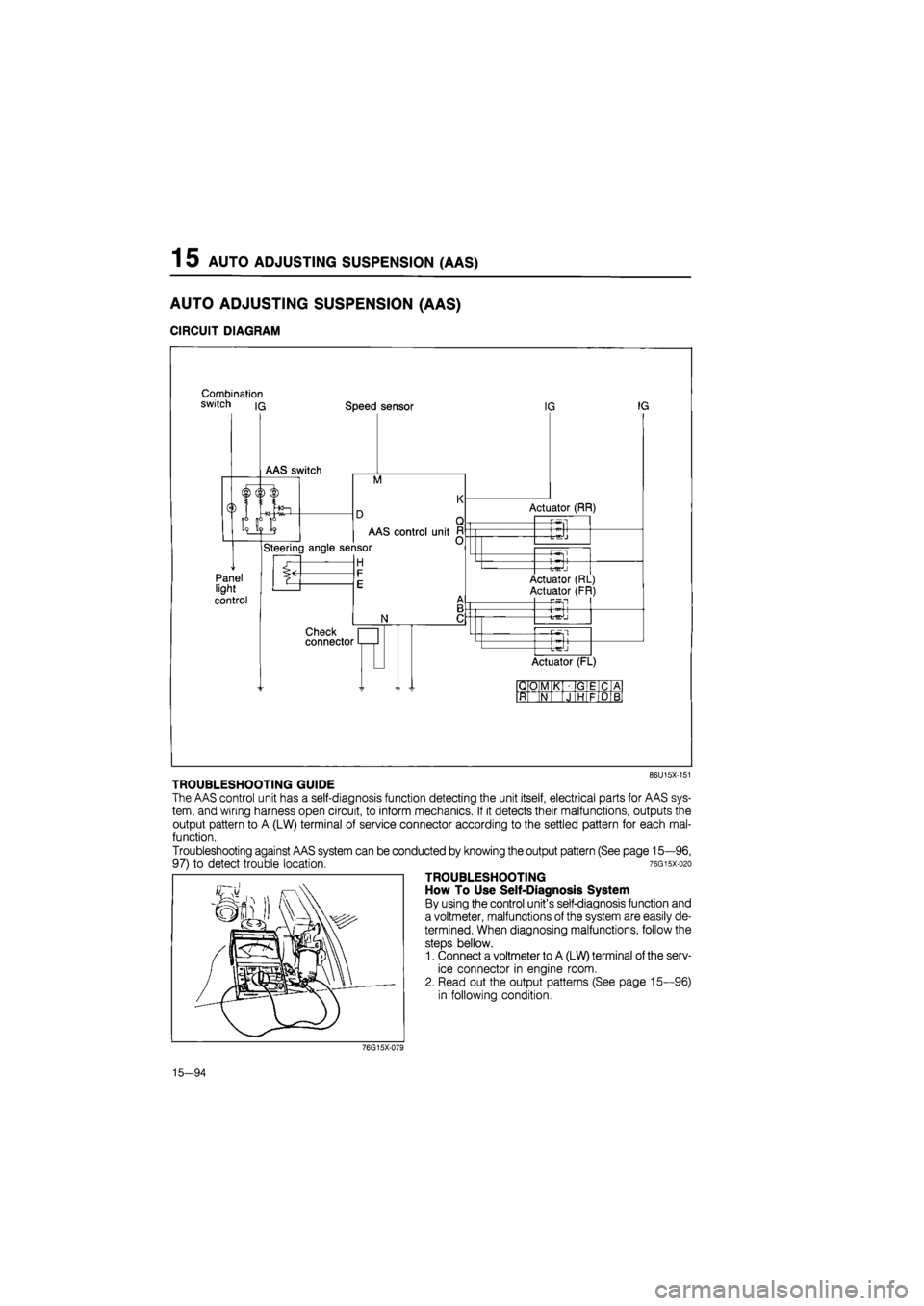
TROUBLESHOOTING GUIDE
The AAS control unit has a self-diagnosis function detecting the unit itself, electrical parts for AAS sys-
tem, and wiring harness open circuit, to inform mechanics. If it detects their malfunctions, outputs the
output pattern to A (LW) terminal of service connector according to the settled pattern for each mal-
function.
Troubleshooting against AAS system can be conducted by knowing the output pattern (See page 15—96,
97) to detect trouble location. 76gisx-o2o
TROUBLESHOOTING
How To Use Self-Diagnosis System
By using the control unit's self-diagnosis function and
a voltmeter, malfunctions of the system are easily de-
termined. When diagnosing malfunctions, follow the
steps bellow.
1. Connect a voltmeter to A (LW) terminal of the serv-
ice connector in engine room.
2. Read out the output patterns (See page 15—96)
in following condition.
76G15X-079
15—94
Page 1845 of 1865

TECHNICAL DATA 30
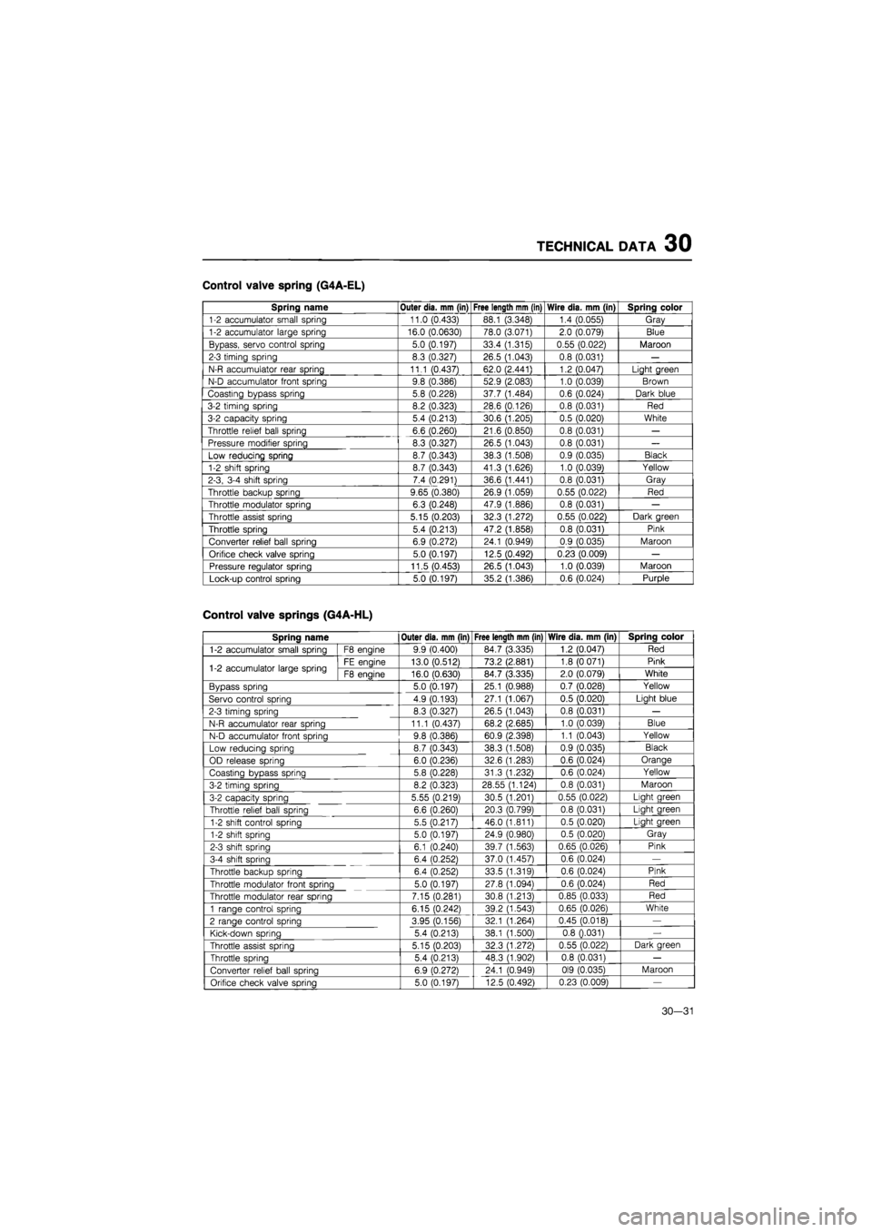
Control valve spring (G4A-EL)
Spring name Outer dia. mm (in) Free length mm (in) Wire dia. mm (in) Spring color
1-2 accumulator small spring 11.0 (0.433) 88.1 (3.348) 1.4 (0.055) Gray
1-2 accumulator large spring 16.0 (0.0630) 78.0 (3.071) 2.0 (0.079) Blue
Bypass, servo control spring 5.0 (0.197) 33.4 (1.315) 0.55 (0.022) Maroon
2-3 timing spring 8.3 (0.327) 26.5 (1.043) 0.8 (0.031)
—
N-R accumulator rear spring 11.1 (0.437) 62.0 (2.441) 1.2 (0.047) Light green
N-D accumulator front spring 9.8 (0.386) 52.9 (2.083) 1.0 (0.039) Brown
Coasting bypass spring 5.8 (0.228) 37.7 (1.484) 0.6 (0.024) Dark blue
3-2 timing spring 8.2 (0.323) 28.6 (0.126) 0.8 (0.031) Red
3-2 capacity spring 5.4 (0.213) 30.6 (1.205) 0.5 (0.020) White
Throttle relief ball spring 6.6 (0.260) 21.6 (0.850) 0.8 (0.031)
—
Pressure modifier spring 8.3 (0.327) 26.5 (1.043) 0.8 (0.031)
—
Low reducing spring 8.7 (0.343) 38.3 (1.508) 0.9 (0.035) Black
1-2 shift spring 8.7 (0.343) 41.3 (1.626) 1.0 (0.039) Yellow
2-3, 3-4 shift spring 7.4 (0.291) 36.6 (1.441) 0.8 (0.031) Gray
Throttle backup spring 9.65 (0.380) 26.9 (1.059) 0.55 (0.022) Red
Throttle modulator spring 6.3 (0.248) 47.9 (1.886) 0.8 (0.031)
—
Throttle assist spring 5.15 (0.203) 32.3 (1.272) 0.55 (0.022) Dark green
Throttle spring 5.4 (0.213) 47.2 (1.858) 0.8 (0.031) Pink
Converter relief ball spring 6.9 (0.272) 24.1 (0.949) 0.9 (0.035) Maroon
Orifice check valve spring 5.0 (0.197) 12.5 (0.492) 0.23 (0.009)
—
Pressure regulator spring 11.5 (0.453) 26.5 (1.043) 1.0 (0.039) Maroon
Lock-up control spring 5.0 (0.197) 35.2 (1.386) 0.6 (0.024) Purple
Control valve springs (G4A-HL)
SDrina name Outer dia. mm (in) Free length mm (in) Wire dia. mm (in) Spring color
1-2 accumulator small spring F8 enaine 9.9 (0.400) 84.7 (3.335) 1.2 (0.047) Red
1-2 accumulator large spring FE engine 13.0 (0.512) 73.2 (2.881) 1.8 (0 071) Pink 1-2 accumulator large spring F8 enaine 16.0 (0.630) 84.7 (3.335) 2.0 (0.079) White
Bypass spring 5.0 (0.197) 25.1 (0.988) 0.7 (0.028) Yellow
Servo control sorina 4.9 (0.193) 27.1 (1.067) 0.5 (0.020) Light blue
2-3 timing soring 8.3 (0.327) 26.5 (1.043) 0.8 (0.031)
—
N-R
accumulator rear SDrina
11.1 (0.437) 68.2 (2.685) 1.0 (0.039) Blue
N-D accumulator front spring 9.8 (0.386) 60.9 (2.398) 1.1 (0.043) Yellow
Low reducing spring 8.7 (0.343) 38.3 (1.508) 0.9 (0.035) Black
OD release spring 6.0 (0.236) 32.6 (1.283) 0.6 (0.024) Orange
Coasting bypass spring 5.8 (0.228) 31.3 (1.232) 0.6 (0.024) Yellow
3-2 timing soring 8.2 (0.323) 28.55 (1.124) 0.8 (0.031) Maroon
3-2 capacity spring 5.55 (0.219) 30.5 (1.201) 0.55 (0.022) Light green
Throttle relief ball soring 6.6 (0.260) 20.3 (0.799) 0.8 (0.031) Light green
1-2 shift control spring 5.5 (0.217) 46.0 (1.811) 0.5 (0.020) Liaht oreen
1-2 shift soring 5.0 (0.197) 24.9 (0.980) 0.5 (0.020) Gray
2-3 shift soring 6.1 (0.240) 39.7 (1.563) 0.65 (0.026) Pink
3-4 shift spring 6.4 (0.252) 37.0 (1.457) 0.6 (0.024)
—
Throttle backup spring 6.4 (0.252) 33.5 (1.319) 0.6 (0.024) Pink
Throttle modulator front spring 5.0 (0.197) 27.8 (1.094) 0.6 (0.024) Red
Throttle modulator rear spring 7.15 (0.281) 30.8 (1.213) 0.85 (0.033) Red
1
ranoe control SDrina
6.15 (0.242) 39.2 (1.543) 0.65 (0.026) White
2 range control spring 3.95 (0.156) 32.1 (1.264) 0.45 (0.018)
—
Kick-down
SDrina
5.4 (0.213) 38.1 (1.500) 0.8 0.031)
—
Throttle assist spring 5.15 (0.203) 32.3 (1.272) 0.55 (0.022) Dark green
Throttle spring 5.4 (0.213) 48.3 (1.902) 0.8 (0.031)
—
Converter relief ball spring 6.9 (0.272) 24.1 (0.949) 0I9 (0.035) Maroon
Orifice check valve soring 5.0 (0.197) 12.5 (0.492) 0.23 (0.009)
—
30—31