1987 MAZDA 626 brake
[x] Cancel search: brakePage 1844 of 1865
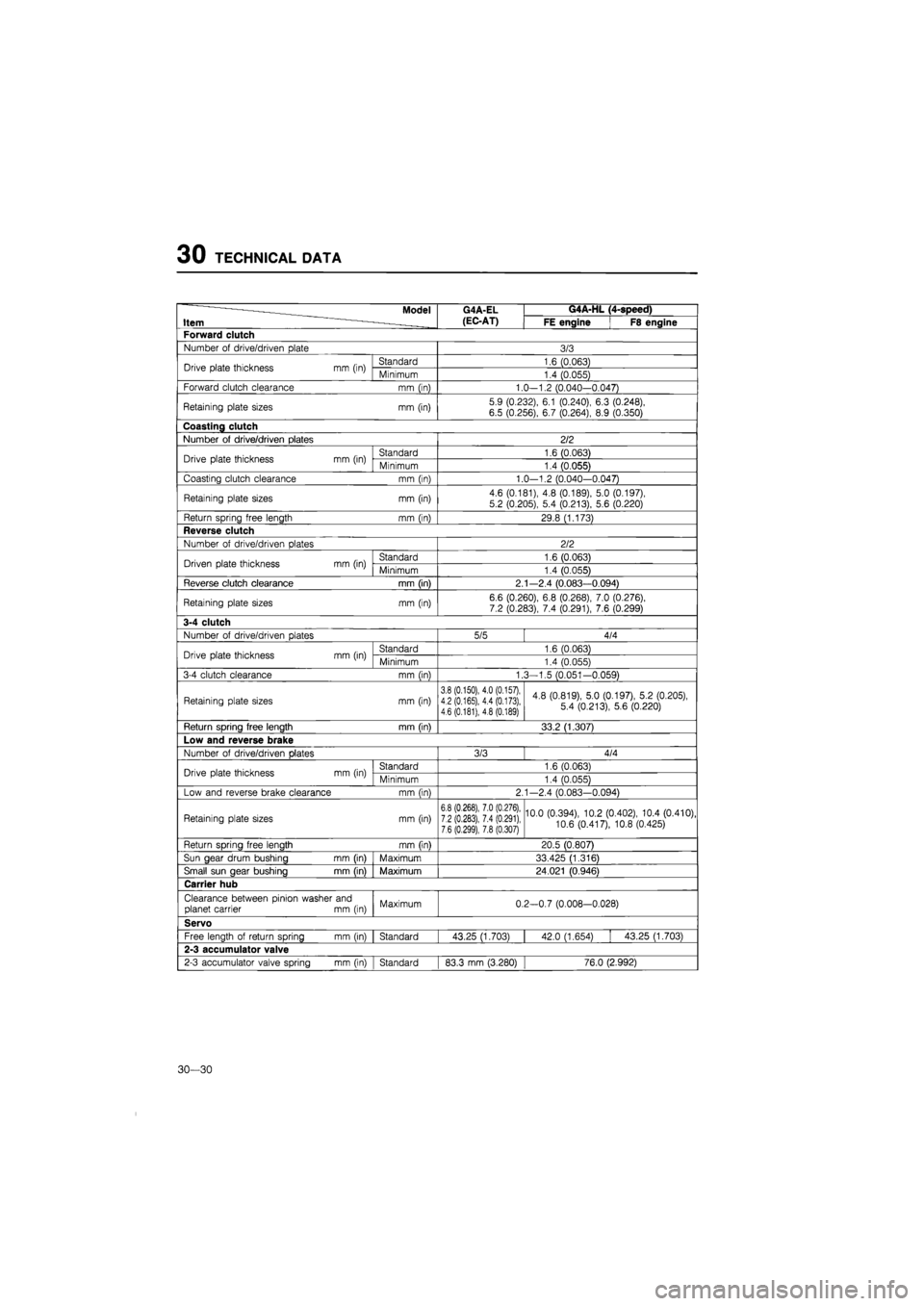
30 TECHNICAL DATA
Model G4A-EL G4A-HL (4-speed)
Item (EC-AT) FE engine F8 engine
Forward clutch
Number
of
drive/driven plate 3/3
Drive plate thickness mm (in) Standard 1.6 (0.063) Drive plate thickness mm (in) Minimum 1.4 (0.055)
Forward clutch clearance mm (in) 1.0—1.2 (0.040—0.047)
Retaining plate sizes mm (in) 5.9 (0.232), 6.1 (0.240), 6.3 (0.248),
6.5 (0.256), 6.7 (0.264),
8.9
(0.350)
Coasting clutch
Number
of
drive/driven plates 2/2
Drive plate thickness mm (in) Standard 1.6 (0.063) Drive plate thickness mm (in) Minimum 1.4 (0.055)
Coasting clutch clearance mm (in) 1.0-1.2 (0.040—0.047)
Retaining plate sizes mm (in) 4.6 (0.181), 4.8 (0.189), 5.0 (0.197),
5.2 (0.205), 5.4 (0.213), 5.6 (0.220)
Return spring free length mm (in) 29.8 (1.173)
Reverse clutch
Number
of
drive/driven plates 2/2
Driven plate thickness mm (in) Standard 1.6 (0.063) Driven plate thickness mm (in) Minimum 1.4 (0.055)
Reverse clutch clearance mm (in) 2.1—2.4 (0.083—0.094)
Retaining plate sizes mm (in) 6.6 (0.260),
6.8
(0.268), 7.0 (0.276), 7.2 (0.283), 7.4 (0.291), 7.6 (0.299)
3-4 clutch
Number
of
drive/driven plates 5/5 4/4
Drive plate thickness mm (in) Standard 1.6 (0.063) Drive plate thickness mm (in) Minimum 1.4 (0.055)
3-4 clutch clearance mm (in) 1.3-1.5 (0.051-0.059)
Retaining plate sizes mm (in) 3.8 (0.150), 4.0 (0.157), 4.2 (0.165), 4.4 (0.173), 4.6 (0.181), 4.8 (0.189)
4.8 (0.819), 5.0 (0.197), 5.2 (0.205), 5.4 (0.213), 5.6 (0.220)
Return spring free length mm fin) 33.2 (1.307)
Low and reverse brake
Number
of
drive/driven Dlates 3/3 4/4
Drive plate thickness mm (in) Standard 1.6 (0.063) Drive plate thickness mm (in) Minimum 1.4 (0.055)
Low and reverse brake clearance mm (in) 2.1-2.4 (0.083-0.094)
Retaining plate sizes mm (in) 6.8 (0,268), 7.0 (0.276), 7.2 (0.283), 7.4 (0.291), 7.6 (0.299), 7.8 (0.307)
10.0 (0.394), 10.2 (0.402), 10.4 (0.410),
10.6 (0.417), 10.8 (0.425)
Return spring free length mm (in) 20.5 (0.807)
Sun gear drum bushing mm (in) Maximum 33.425 (1.316)
Small sun gear bushing mm (in) Maximum 24.021 (0.946)
Carrier hub
Clearance between pinion washer and planet carrier
mm (in)
Maximum 0.2-0.7 (0.008-0.028)
Servo
Free length
of
return spring mm (in) Standard 43.25 (1.703) 42.0 (1.654) 43.25 (1.703)
2-3 accumulator valve
2-3 accumulator valve spring mm (in) Standard 83.3
mm
(3.280) 76.0 (2.992)
30—30
Page 1847 of 1865
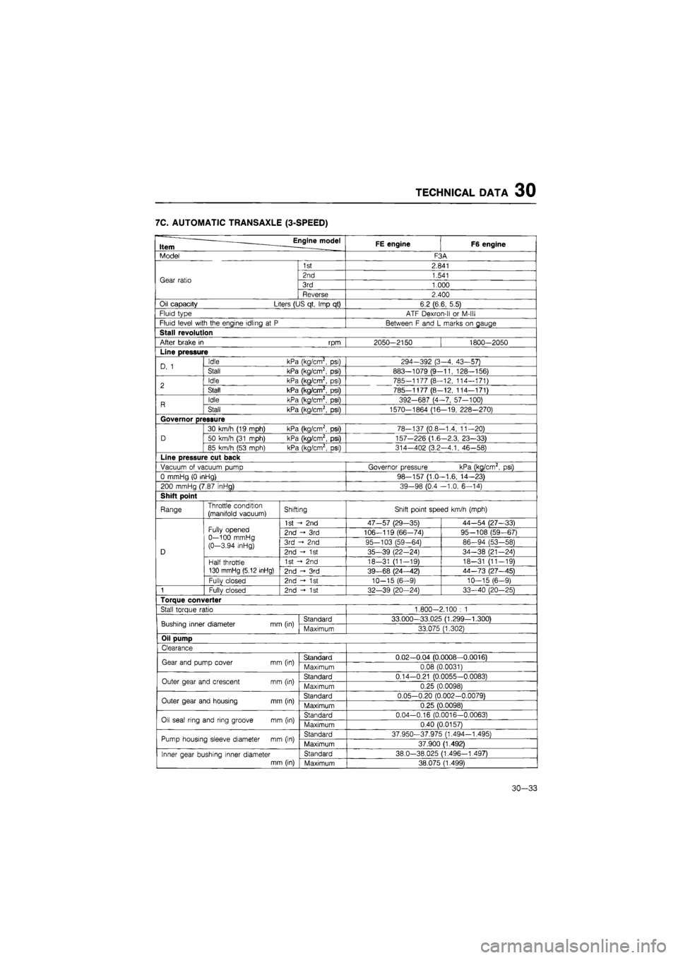
TECHNICAL DATA 30
7C. AUTOMATIC TRANSAXLE (3-SPEED)
Engine model Item FE engine F6 engine
Model F3A
Gear ratio
1st 2.841
Gear ratio 2nd 1.541 Gear ratio 3rd 1.000 Gear ratio
Reverse 2.400
Oil capacity Liters (US qt, Imp
qt)
6.2 (6.6, 5.5)
Fluid type ATF Dexron-ll
or
M-lll
Fluid level with the engine idling
at P
Between
F
and
L
marks
on
gauge
Stall revolution
After brake
in rpm
2050-2150 1800—2050
Line pressure
D,
1
Idle kPa (kg/cm2,
psi)
294-392 (3-4, 43-57) D,
1
Stall kPa (kg/cm2,
psi)
883—1079 (9-11, 128-156)
2 Idle kPa (kg/cm2,
psi)
785-1177 (8—12, 114-171) 2 Stall kPa (kg/cm2,
psi)
785-1177 (8-12, 114—171)
R Idle kPa (kg/cm2,
psi)
392-687 (4-7, 57-100) R Stall kPa (kg/cm2,
psi)
1570-1864 (16-19, 228—270)
Governor pressure
D
30 km/h (19 mph) kPa (kg/cm2,
psi)
78-137 (0.8-1.4, 11-20)
D 50 km/h (31 mph) kPa (kg/cm2, psi) 157-226 (1.6-2.3, 23-33) D
85 km/h
(53
mph) kPa (kg/cm2,
psi)
314-402 (3.2—4.1, 46—58)
Line pressure cut back
Vacuum
of
vacuum pump Governor pressure kPa (kg/cm2,
psi)
0 mmHg
(0
inHg) 98-157 (1.0—1.6, 14—23)
200 mmHg (7.87 inHg) 39-98 (0.4 -1.0, 6-14)
Shift point
Range Throttle condition (manifold vacuum) Shifting Shift point speed km/h (mph)
D
Fully opened 0—100 mmHg (0-3.94 inHg)
1st
- 2nd
47-57 (29-35) 44—54 (27—33)
D
Fully opened 0—100 mmHg (0-3.94 inHg)
2nd
- 3rd
106—119 (66-74) 95—108 (59—67)
D
Fully opened 0—100 mmHg (0-3.94 inHg) 3rd
2nd
95-103 (59-64) 86—94 (53-58)
D
Fully opened 0—100 mmHg (0-3.94 inHg) 2nd -<•
1st
35-39 (22-24) 34-38 (21—24) D
Half throttle 130 mmHg (5.12 inHg)
1st
- 2nd
18-31 (11-19) 18-31 (11-19)
D
Half throttle 130 mmHg (5.12 inHg) 2nd
- 3rd
39-68 (24—42) 44-73 (27—45)
D
Fullv closed 2nd
- 1st
10-15 (6-9) 10—15 (6—9)
1 Fully closed 2nd -»•
1st
32—39 (20—24) 33—40 (20—25)
Torque converter
Stall torque ratio 1.800-2.100
: 1
Bushing inner diameter mm (in) Standard 33.000—33.025 (1.299—1.300) Bushing inner diameter mm (in) Maximum 33.075 (1.302)
Oil pump
Clearance
Gear and pump cover
mm
(in) Standard 0.02—0.04 (0.0008—0.0016) Gear and pump cover
mm
(in) Maximum 0.08 (0.0031)
Outer gear and crescent
mm
(in) Standard 0.14-0.21 (0.0055-0.0083) Outer gear and crescent
mm
(in) Maximum 0.25 (0.0098)
Outer gear and housing
mm
(in) Standard 0.05-0.20 (0.002-0.0079) Outer gear and housing
mm
(in) Maximum 0.25 (0.0098)
Oil seal ring and ring groove
mm
(in) Standard 0.04-0.16 (0.0016-0.0063) Oil seal ring and ring groove
mm
(in) Maximum 0.40 (0.0157)
Pump housing sleeve diameter
mm
(in) Standard 37.950-37.975 (1.494-1.495) Pump housing sleeve diameter
mm
(in) Maximum 37.900 (1.492)
Inner gear bushing inner diameter mm (in)
Standard 38.0-38.025 (1.496—1.497) Inner gear bushing inner diameter mm (in) Maximum 38.075 (1.499)
30—33
Page 1848 of 1865
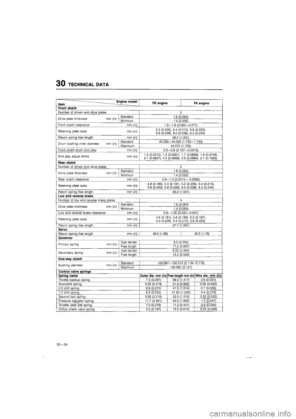
30 TECHNICAL DATA
Item Engine model FE engine F6 engine
Front clutch
Number
of
driven and drive plates 3
Drive plate thickness mm (in) Standard 1.6 (0.063) Drive plate thickness mm (in) Minimum 1.4 (0.055)
Front clutch clearance mm (in) 1.6-1.8 (0.063-0.071)
Retaining plate sizes mm (in) 5.2 (0.205), 5.4 (0.213), 5.6 (0.220),
5.8 (0.228), 6.0 (0.236), 6.2 (0.244)
Return spring free length mm (in) 26.2 (1.031)
Drum bushing inner diameter mm (in) Standard 44.000-44.025 (1.732-1.733) Drum bushing inner diameter mm (in) Maximum 44.075 (1.735)
Front clutch drum end play mm (in) 0.5-0.8 (0.197-0.0315)
End play adjust shims mm (in) 1.3 (0.0512), 1.5 (0.0591), 1.7 (0.0669), 1.9 (0.0748), 2.1 (0.0827), 2.3 (0.0906),
2.5
(0.0984), 2.7 (0.1063)
Rear clutch
Number
of
driven and drive plates 4
Drive plate thickness mm (in) Standard 1.6 (0.063) Drive plate thickness mm (in) Minimum 1.4 (0.055)
Rear clutch clearance mm (in) 0.8--1.0 (0.0315- 0.0394)
Retaining plate sizes mm (in) 4.8 (0.189), 5.0 (0.197), 5.2 (0.205), 5.4 (0.213),
5.6 (0.220), 5.8 (0.228), 6.0 (0.236), 6.2 (0.244)
Return spring free length mm (in) 26.2 (1.031)
Low and reverse brake
Number
of
low and reverse brake plates 4
Drive plate thickness mm (in) Standard 1.6 (0.063) Drive plate thickness mm (in) Minimum 1.4 (0.055)
Low and reverse brake clearance mm (in) 0.8-1.05 (0.032-0.041)
Retaining plate sizes mm (in) 4.6 (0.181),
4.8
(0.189), 5.0 (0.197), 5.2 (0.205), 5.4 (0.213), 5.6 (0.220)
Return spring free length mm (in) 27.7 (1.091)
Servo
Return sprina free lenath mm (in) 48.0 (1.89) 45.5 (1.79)
Governor
Primary spring mm (in) Outer diameter 9.0 (0.354) Primary spring mm (in) Free lenath 17.2 (0.667)
Secondary spring mm (in) Outer diameter 9.25 (0.364) Secondary spring mm (in) Free lenath 13.2 (0.520)
One-wav clutch
Bushing diameter mm (in) Standard 129.987-130.013 (5.118--5.119) Bushing diameter mm (in) Maximum 130.063 (5.121)
Control valve SDrinas
Spring name Outer dia. mm (in) Free length mm (in) Wire dia. mm (in)
Throttle backup spring 7.3 (0.287) 36.0 (1.417) 0.8 (0.031)
Downshift sorina 5.55 (0.219) 21.9 (0.862) 0.55 (0.022)
2-3 shift spring 6.9 (0.272) 41.0 (1.614) 0.7 (0.028)
1-2 shift spring 6.4 (0.252) 31.63 (1.245) 0.4 (0.016)
Second lock spring 5.55 (0.219) 33.5 (1.319) 0.55 (0.022)
Pressure reaulator sprina 11.7 (0.461) 43.0 (1.693) 1.2 (0.047)
Throttle relief ball spring 7.0 (0.276) 11.2 (0.441) 0.9 (0.035)
Orifice check valve sprina 5.0 (0.197) 15.5 (0.610) 0.23 (0.009)
30-34
Page 1851 of 1865
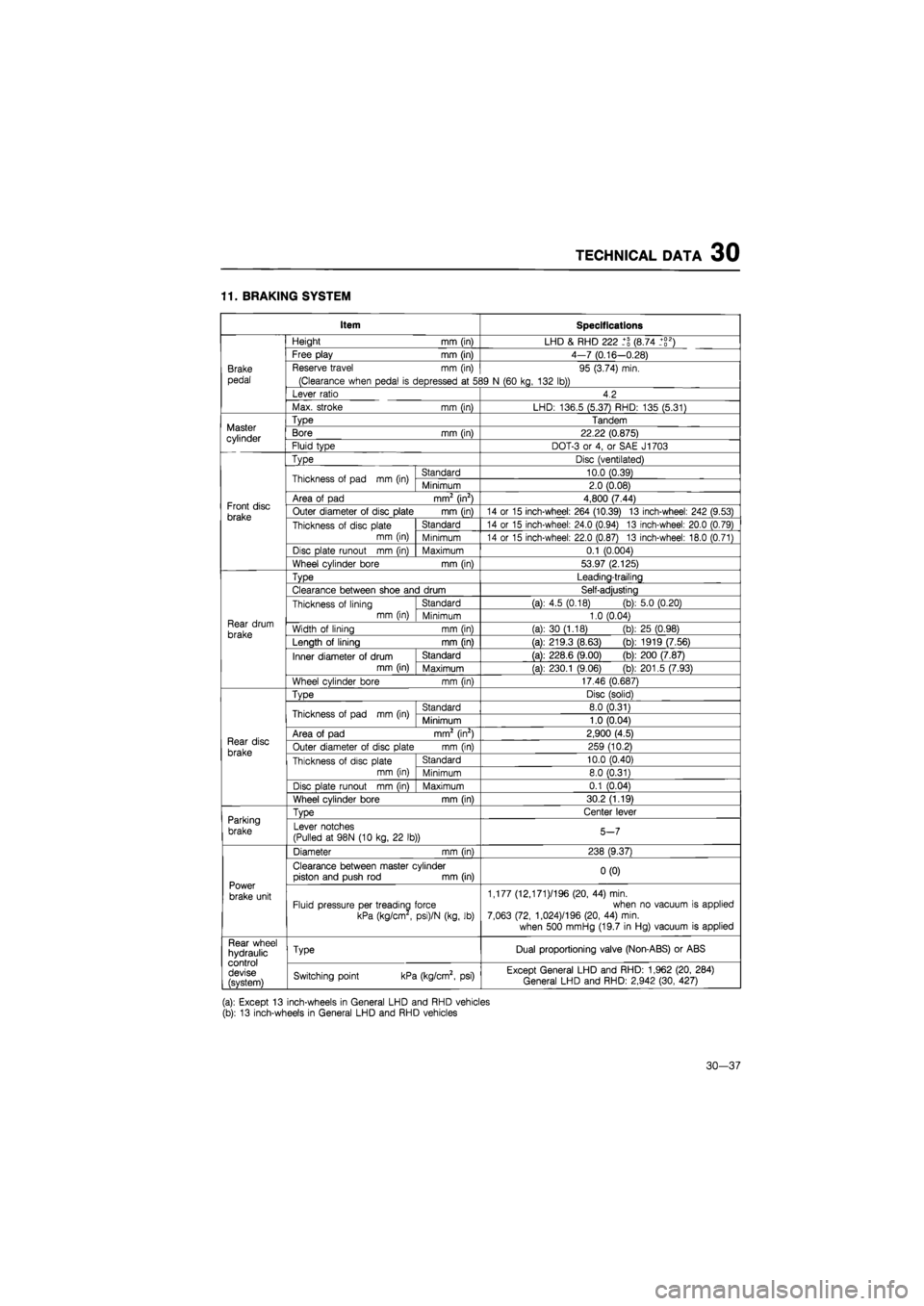
TECHNICAL DATA 30
11. BRAKING SYSTEM
Item Specifications
Brake
pedal
Height
mm
(in) LHD
&
RHD 222 (8.74 _+g2)
Brake
pedal
Free play
mm
(in) 4-7 (0.16—0.28)
Brake
pedal
Reserve travel
mm (in)
(Clearance when pedal
is
depressed
at 5S
95 (3.74) min.
39
N
(60 kg, 132 lb))
Brake
pedal
Lever ratio 4.2
Brake
pedal
Max. stroke
mm (in)
LHD: 136.5 (5.37) RHD: 135 (5.31)
Master cylinder
Type Tandem Master cylinder Bore
mm
(in) 22.22 (0.875) Master cylinder Fluid type DOT-3
or 4, or
SAE J1703
Front disc brake
Type Disc (ventilated)
Front disc brake
Thickness
of
pad
mm (in)
Standard 10.0 (0.39)
Front disc brake
Thickness
of
pad
mm (in)
Minimum 2.0 (0.08)
Front disc brake
Area
of
pad mm2 (in2) 4,800 (7.44) Front disc brake Outer diameter
of
disc plate
mm (in)
14
or 15
inch-wheel: 264 (10.39)
13
inch-wheel: 242 (9.53) Front disc brake Thickness
of
disc plate
mm (in)
Standard 14
or 15
inch-wheel: 24.0 (0.94)
13
inch-wheel: 20.0 (0.79)
Front disc brake Thickness
of
disc plate
mm (in) Minimum 14
or 15
inch-wheel: 22.0 (0.87)
13
inch-wheel: 18.0 (0.71)
Front disc brake
Disc plate runout
mm (in)
Maximum 0.1 (0.004)
Front disc brake
Wheel cylinder bore
mm (in)
53.97 (2.125)
Rear drum
brake
Type Leading-trailing
Rear drum
brake
Clearance between shoe and drum Self-adjusting
Rear drum
brake
Thickness
of
lining mm (in)
Standard (a):
4.5
(0.18) (b): 5.0 (0.20)
Rear drum
brake
Thickness
of
lining mm (in) Minimum 1.0 (0.04) Rear drum
brake Width
of
lining
mm (in)
(a):
30
(1.18)
(b)
25 (0.98) Rear drum
brake Length
of
lining
mm fin)
(a): 219.3 (8.63)
(b)
1919 (7.56)
Rear drum
brake
Inner diameter
of
drum mm (in)
Standard (a): 228.6 (9.00)
(b)
200 (7.87)
Rear drum
brake
Inner diameter
of
drum mm (in) Maximum (a): 230.1 (9.06)
(b)
201.5 (7.93)
Rear drum
brake
Wheel cylinder bore
mm (in)
17.46 (0.687)
Rear disc
brake
TvDe Disc (solid)
Rear disc
brake
Thickness
of
pad
mm (in)
Standard 8.0 (0.31)
Rear disc
brake
Thickness
of
pad
mm (in)
Minimum 1.0 (0.04)
Rear disc
brake
Area
of
pad mm2 (in2) 2,900 (4.5) Rear disc
brake Outer diameter
of
disc plate
mm (in)
259 (10.2) Rear disc
brake Thickness
of
disc plate mm (in)
Standard 10.0 (0.40)
Rear disc
brake Thickness
of
disc plate mm (in) Minimum 8.0 (0.31)
Rear disc
brake
Disc
Dlate runout mm fin)
Maximum 0.1 (0.04)
Rear disc
brake
Wheel cylinder bore
mm (in)
30.2 (1.19)
Parking
brake
TvDe Center lever Parking
brake Lever notches
(Pulled
at
98N
(10
kg,
22 lb))
5-7
Power
brake unit
Diameter
mm (in)
238 (9.37)
Power
brake unit
Clearance between master cylinder piston and push
rod mm
(in) 0(0)
Power
brake unit Fluid pressure per treading force
kPa (kg/cm
,
psi)/N (kg,
lb)
1,177 (12,171 )/196 (20,
44)
min. when
no
vacuum
is
applied 7,063 (72, 1,024)/196 (20,
44)
min.
when 500 mmHg (19.7
in
Hg) vacuum
is
applied
Rear wheel hydraulic control devise (svstem)
Type Dual proportioning valve (Non-ABS)
or
ABS Rear wheel hydraulic control devise (svstem) Switching point kPa (kg/cm2,
psi)
Except General LHD and RHD: 1,962 (20, 284) General LHD and RHD: 2,942 (30, 427)
(a): Except
13
inch-wheels
in
General LHD and RHD vehicles (b):
13
inch-wheels
in
General LHD and RHD vehicles
30—37
Page 1854 of 1865
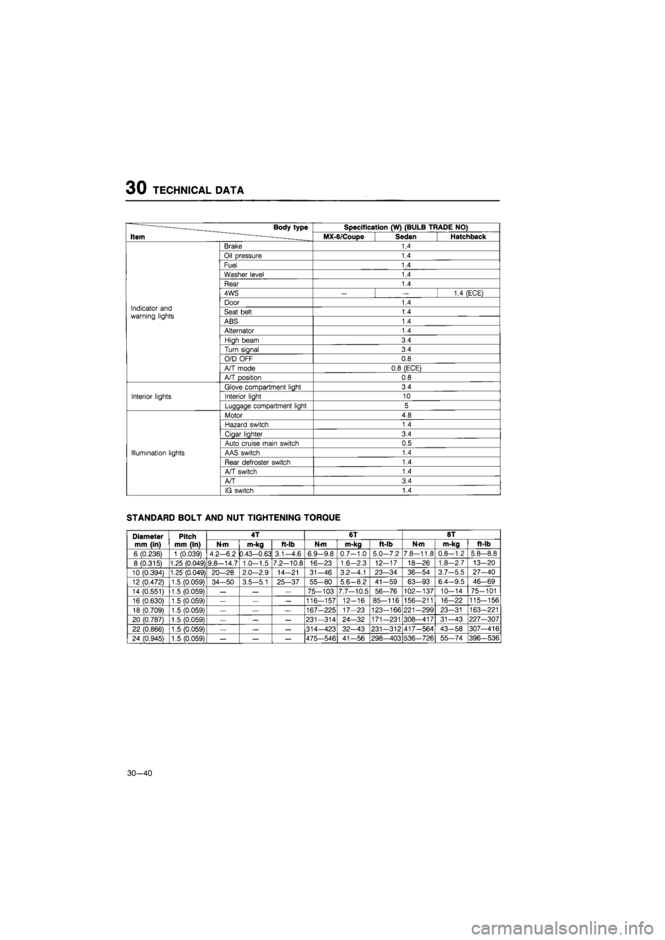
30 TECHNICAL DATA
Body type Specification (W) (BULB TRADE NO)
Item MX-6/Coupe Sedan Hatchback
Brake 1.4
Oil pressure 1.4
Fuel 1.4
Washer level 1.4
Rear 1.4
4WS
— —
1.4 (ECE)
Indicator and warning lights
Door 1.4 Indicator and warning lights Seat belt 1.4 Indicator and warning lights ABS 1.4
Alternator 1.4
High beam 3.4
Turn signal 3.4
O/D OFF 0.8
A/T mode 0.8 (ECE)
A/T position 0.8
Glove compartment light 3.4
Interior lights Interior light 10
Luggage compartment light 5
Motor 4.8
Hazard switch 1.4
Cigar lighter 3.4
Auto cruise main switch 0.5
Illumination lights AAS switch 1.4
Rear defroster switch 1.4
A/T switch 1.4
A/T 3.4
IG switch 1.4
STANDARD BOLT AND NUT TIGHTENING TORQUE
Diameter
mm (in)
Pitch
mm (in)
4T 6T 8T Diameter
mm (in)
Pitch
mm (in) N-m m-kg ft-lb N-m m-kg ft-lb N-m m-kg ft-lb
6 (0.236) 1 (0.039) 4.2-6.2 0.43-0.63 3.1-4.6 6.9-9.8 0.7-1.0 5.0-7.2 7.8-11.8 0.8-1.2 5.8—8.8
8 (0.315) 1.25 (0.049) 9.8—14.7 1.0-1.5 7.2-10.8 16-23 1.6-2.3 12-17 18—26 1.8-2.7 13-20
10 (0.394) 1.25 (0.049) 20-28 2.0—2.9 14-21 31-46 3.2-4.1 23—34 36-54 3.7-5.5 27-40
12 (0.472) 1.5 (0.059) 34—50 3.5-5.1 25-37 55-80 5,6-8.2 41-59 63-93 6.4-9.5 46-69
14 (0.551) 1.5 (0.059)
— — —
75-103 7.7-10.5 56-76 102—137 10-14 75-101
16 (0.630) 1.5 (0.059)
— — —
116-157 12-16 85-116 156-211 16-22 115-156
18 (0.709) 1.5 (0.059)
— — —
167-225 17-23 123-166 221-299 23-31 163—221
20 (0.787) 1.5 (0.059)
— — —
231-314 24-32 171-231 308—417 31-43 227-307
22 (0.866) 1.5 (0.059)
— — —
314—423 32-43 231-312 417—564 43-58 307-416
24 (0.945) 1.5 (0.059)
— — —
475—546 41—56 298—403 536-726 55-74 396-536
30—40
Page 1855 of 1865
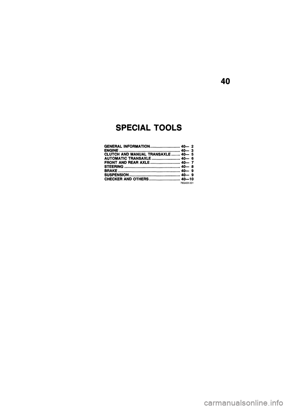
40
SPECIAL TOOLS
GENERAL INFORMATION 40— 2
ENGINE 40- 3
CLUTCH AND MANUAL TRANSAXLE 40- 5
AUTOMATIC TRANSAXLE 40— 6
FRONT AND REAR AXLE 40— 7
STEERING 40— 8
BRAKE 40— 9
SUSPENSION 40— 9
CHECKER AND OTHERS 40—10 76G40X-001
Page 1857 of 1865
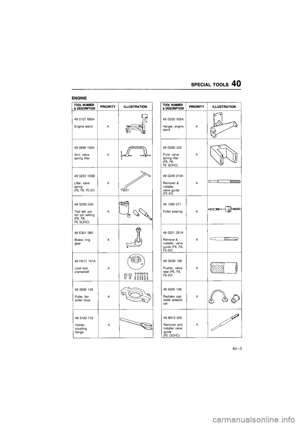
SPECIAL TOOLS 40
ENGINE
TOOL NUMBER & DESCRIPTION PRIORITY ILLUSTRATION
49 0107 680A
Engine stand A
V
ir==JJ
i
49 0636 100A
Arm, valve
spring lifter
A \JL
JL
49 0223 105B
Lifter, valve spring
(F6, F8, FE-2V)
A
49 G030 040
Tool set,
pis-
ton pin setting (F6,
F8,
FE SOHC)
A
49 E301
060
Brake, ring
gear
A
J
49 H011 101A
Lock tool,
crankshaft
A
ft
im
49 0636
145
Puller,
fan
puller boss A
49 S120 710
Holder, coupling
flange
A
TOOL NUMBER & DESCRIPTION PRIORITY ILLUSTRATION
49 G030 005A
Hanger, engine stand A
|i
l\fy ^
49 G030 222
Pivot, valve spring lifter (F6,
F8,
FE SOHC)
A
r
o
49 0249 01 OA
Remover
&
installer, valve guide (FE-3V)
A
49 0249 01 OA
Remover
&
installer, valve guide (FE-3V)
A
c ii&zm
49 0249 01 OA
Remover
&
installer, valve guide (FE-3V)
A
49 1285 071
Puller bearing A
49 0221 251A
Remove
&
installer, valve
guide (F6,
F8,
FE-2V)
A
cr-
49 G030
160
Pusher, valve
seal (F6,
F8,
FE-2V)
A
if !
49 9200
146
Radiator cap tester adaptor set
A
49 B012 005
Remover and installer valve guide
(FE DOHC)
A
40—3
Page 1858 of 1865
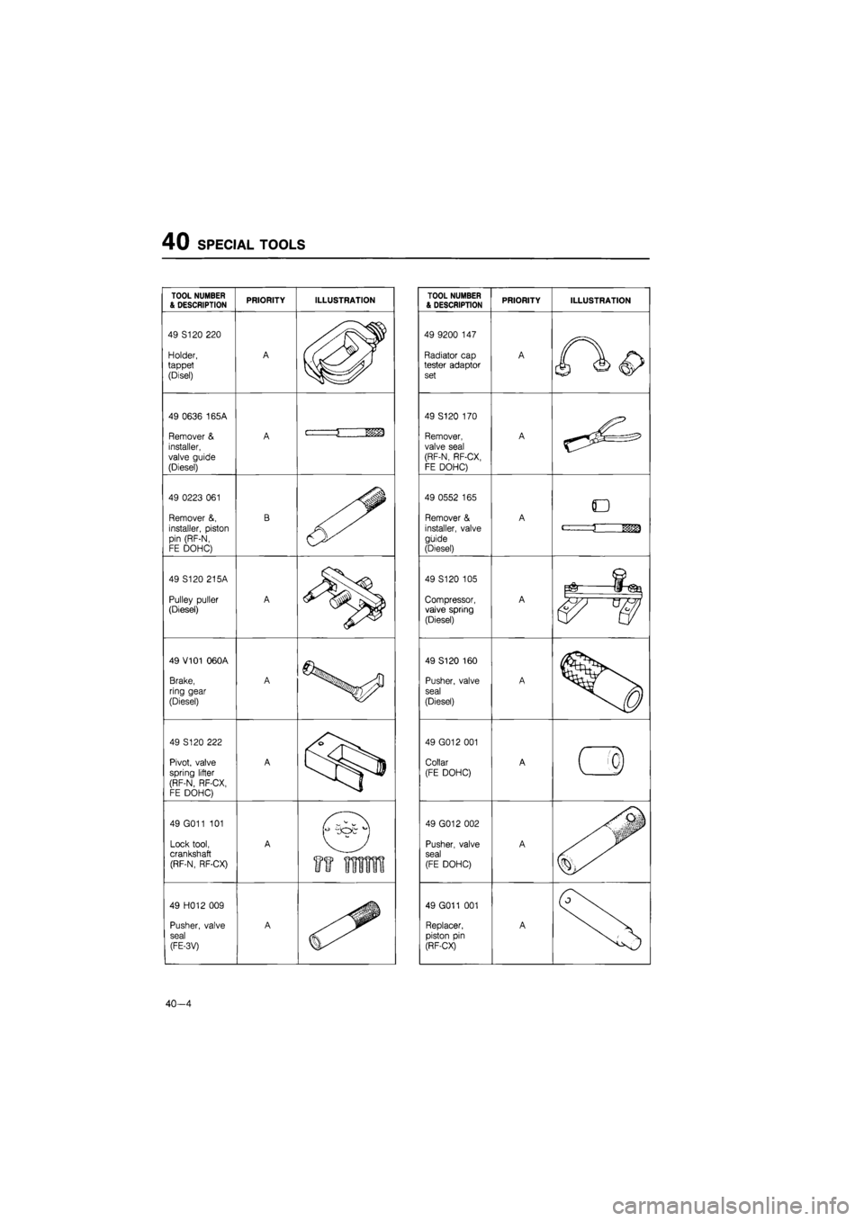
40 SPECIAL TOOLS
TOOL NUMBER & DESCRIPTION PRIORITY ILLUSTRATION
49 S120 220
Holder, tappet
(Disel)
A
49 0636 165A
Remover
&
installer,
valve guide
(Diesel)
A i
1 vrn
49 0223
061
Remover
&,
installer, piston pin (RF-N, FE DOHC)
B
49 S120 215A
Pulley puller (Diesel)
A
49 V101 060A
Brake,
ring gear
(Diesel)
A
49 S120 222
Pivot, valve spring lifter (RF-N, RF-CX, FE DOHC)
A
49 G011
101
Lock tool, crankshaft (RF-N, RF-CX)
A
49 H012 009
Pusher, valve
seal
(FE-3V)
A
40-4
TOOL NUMBER & DESCRIPTION PRIORITY ILLUSTRATION
49 9200
147
Radiator cap tester adaptor set
A
49 S120 170
Remover, valve seal (RF-N, RF-CX, FE DOHC)
A
49 0552
165
Remover
&
installer, valve guide (Diesel)
A D
<-—j
nm
49 S120 105
Compressor, valve spring (Diesel)
A
S-tSfe
49 S120 105
Compressor, valve spring (Diesel)
A
49 S120 160
Pusher, valve
seal
(Diesel)
A
49 G012 001
Collar (FE DOHC) A
( 4
49 G012 002
Pusher, valve seal (FE DOHC)
A
49 G011
001
Replacer,
piston
pin
(RF-CX)
A