Page 1494 of 1865

WHEELS AND TIRES 1 2
86U12X-004
\k
y
i jYj
/ <4/
/ v Wear platform
Wear indicators
86U12X-005
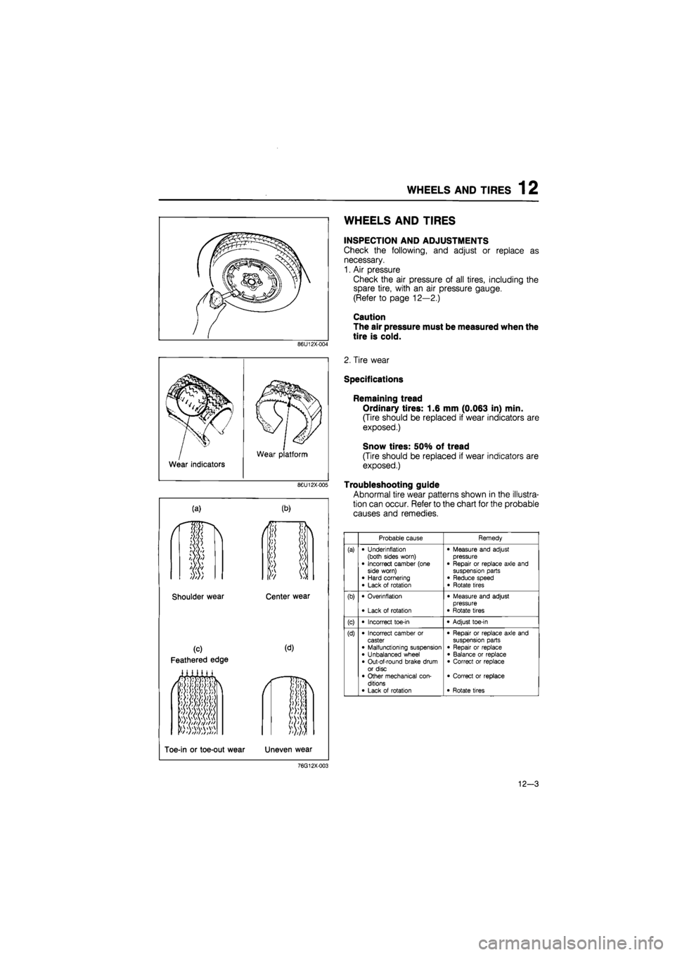
(a) (b)
Shoulder wear Center wear
(c)
Feathered edge
(d)
*f tftiit t
Toe-in or toe-out wear Uneven wear
WHEELS AND TIRES
INSPECTION AND ADJUSTMENTS
Check the following, and adjust or replace as
necessary.
1. Air pressure
Check the air pressure of all tires, including the
spare tire, with an air pressure gauge.
(Refer to page 12—2.)
Caution
The air pressure must be measured when the
tire is cold.
2. Tire wear
Specifications
Remaining tread
Ordinary tires: 1.6 mm (0.063 in) min.
(Tire should be replaced if wear indicators are
exposed.)
Snow tires: 50% of tread
(Tire should be replaced if wear indicators are
exposed.)
Troubleshooting guide
Abnormal tire wear patterns shown in the illustra-
tion can occur. Refer to the chart for the probable
causes and remedies.
Probable cause Remedy
(a) • Underinflation (both sides worn) • Incorrect camber (one side worn) • Hard cornering • Lack of rotation
• Measure and adjust pressure • Repair or replace axle and suspension parts • Reduce speed • Rotate tires
(b) • Overinflation
• Lack of rotation
• Measure and adjust pressure • Rotate tires
(c) • Incorrect toe-in • Adjust toe-in
(d) • Incorrect camber or caster • Malfunctioning suspension • Unbalanced wheel • Out-of-round brake drum or disc • Other mechanical con-ditions • Lack of rotation
• Repair or replace axle and suspension parts • Repair or replace • Balance or replace • Correct or replace
• Correct or replace
• Rotate tires
76G12X-003
12-3
Page 1502 of 1865

OUTLINE 13
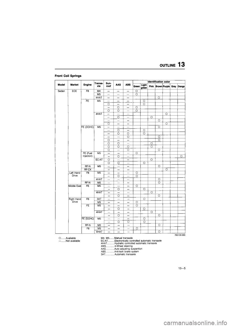
Front Coil Springs
Transa-
xle
Sun-
roof
Identification color
Model Market Engine Transa-
xle
Sun-
roof AAS ABS Green Light
green Pink Brown Purple Gray Orange
Sedan ECE F8 M4 — — — O
M5 — — — 0
4HAT — — — O
FE M5 — — — O
0 — — O
— o — o
o o — o
4HAT -— — o
— o — O
— — — o
o — — o
FE (DOHC) M5 — — — o
— o — 0
— o o o
— — o o
0 — — o
o o — o
0 0 o o
o — 0 o
FE (Fuel M5 — — — o
Injection) — 0 — O
EC-AT O — — o
o o — o
RF-N M5 — — — 0
RF-CX — — — o
Left Hand F8 M5 — — — o
Drive „ o — o
4HAT — — — o
RF-N M5 — — — o
Middle East FE M5 — — — o
-o — o
4HAT — — — o
— o — 0
Right Hand F6 3AT — — — 0
Drive M5 — — — o
FE M5 — — — 0
— o _ o
4HAT — — — o
— 0 — o
FE (DOHC) M5 — — — o
— o o 0
RF-N M5 — — — o
F8 M5 — — — 0
4HAT — — — o
76G13X003
O Available M4, M5.... ...Manual transaxle
— Not available EC-AT ....Electronically controlled automatic transaxle 4HAT ....Hydrallic controlled automatic transaxle
4WS ... 4-Wheel steering
AAS ....Auto adjusting suspention ABS ....Anti-lock brake system
3AT ... Automatic transaxle
13—5
Page 1505 of 1865

13 OUTLINE
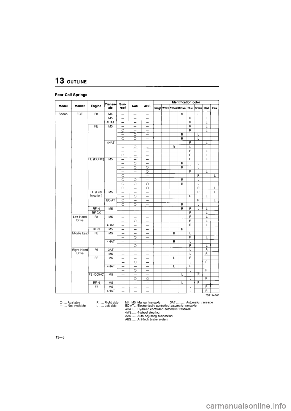
Rear Coil Springs
Transa-xle
Sun-
roof
Identification color
Model Market Engine Transa-xle
Sun-
roof AAS ABS Orange White Yellow Brown Blue Green Red Pink
Sedan ECE F8 M4 — — — R L
M5 — — — R L
4HAT — — R L
FE M5 — — — R L
— — R L
— o — R L
O 0 — R L
4HAT — „ — R L
— 0 — R L
— — — R L
o — — R L
FE (DOHC) M5 — — — R L
— o — R L
— o 0 R L
— — o R L
0 — — R L
0 o — R L
o 0 0 R L
o — o R L
FE (Fuel M5 — — — R L
Injection) — o — R L
EC-AT o — — R L
o o — R L
RF-N M5 — — — R R L L
RF-CX _ — — R L
Left Hand F8 M5 — — — R L
Drive — o — R L
4HAT — — — R L
RF-N M5 — — — R L
Middle East FE M5 — — — R L
— o — n L
4HAT — — — R L
— o — L
Right Hand F6 3AT — — — L R
Drive M5 — — — L R
FE M5 — — — L
— o — L R
4HAT — — — L
— o — L R
FE (DOHC) M5 — — — L R — o o L R
RF-N M5 — — L R
F8 M5 — — — L R
4HAT — — — L R
76G13X-006
0 Available R Right side M4, M5 Manual transaxle 3AT Automatic transaxle — Not available L Left side EC-AT... Electronically controlled automatic transaxle 4HAT..., Hydrallic controlled automatic transaxle 4WS...... 4-wheef steering AAS Auto adjusting suspention ABS Anti-lock brake system
13-8
Page 1508 of 1865

TROUBLESHOOTING GUIDE 1 3
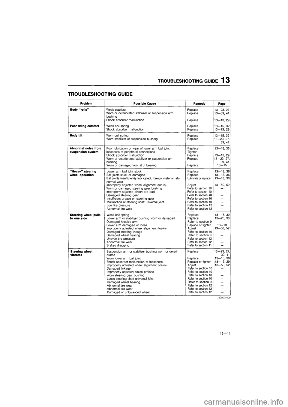
TROUBLESHOOTING GUIDE
Problem Possible Cause Remedy Page
Body "rolls" Weak stabilizer Replace 13-23, 27 Worn or deteriorated stabilizer or suspension arm Replace 13—39, 41 bushing
Shock absorber malfunction Replace 13-13, 29
Poor riding comfort Weak coil spring Replace 13-15, 32 Shock absorber malfunction Replace 13-13. 29
Body tilt Worn coil spring Replace 13-15, 32 Worn stabilizer of suspension bushing Replace 13-23, 27,
39, 41
Abnormal noise from Poor lubrication or wear of lower arm ball joint Replace 13-18, 36 suspension system looseness of peripheral connections Tighten
Shock absorber malfunction Replace 13-13, 29 Worn or deteriorated stabilizer or suspension arm Replace 13—23, 27, bushing 39, 41 Worn or damaged front strut bearing Replace 13-15
"Heavy" steering Lower arm ball joint stuck Replace 13—18, 36
wheel operation Ball joints stuck or damaged Replace 13-18, 36
Ball joints insufficiently lubricated; foreign material; ab-Lubricate or replace 13-18, 36
normal wear Improperly adjusted wheel alignment (toe-in) Adjust 13-50, 52
Worn or damaged steering gear bushing Refer to section 10 —
Improperly adjusted pinion pre-load Refer to section 10 —
Damaged steering gear Refer to section 10 —
Insufficient grease on steering gear Refer to section 10 —
Malfunction of steering shaft universal joint Refer to section 10 —
Low tire pressure Refer to section 12 —
Abnormal tire wear Refer to section 12 —
Steering wheel pulls Weak coil spring Replace 13-15, 32
to one side Lower arm or stabilizer bushing worn or damaged Replace 13-20, 38
Damaged knuckle arm Refer to section 9 —
Lower arm damaged or loose Replace or tighten 13-18 Improperly adjusted wheel alignment (toe-in) Adjust 13-50, 52
Damaged steering linkage Refer to section 10 —
Damaged wheel bearing Refer to section 9 —
Uneven tire pressure Refer to section 12 —
Abnormal tire wear Refer to section 12 —
Brakes dragging Refer to section 11 —
Steering wheel Suspension arm or stabilizer bushing worn or deteri-Replace 13—23, 27.
vibrates orated 39, 41
Worn lower arm ball joint Replace 13-18, 36
Shock absorber malfunction or looseness Replace or tighten 13-13, 29
Improperly adjusted wheel alignment (toe-in) Adjust 13-50, 52 Damaged linkage Refer to section 10
Improperly adjusted pinion preload Refer to section 10
Worn steering gear bushing Refer to section 10 —
Loose steering shaft universal joint Refer to section 10 —
Damaged wheel bearing Refer to section 9 —
Abnormal tire wear Refer to section 12 —
Abnormal tire wear Refer to section 12 —
Damaged or unbalanced wheel Refer to section 12 —
76G13X-009
13—11
Page 1541 of 1865
1 3 REAR CROSSMEMBER (4WS)
REAR CROSSMEMBER (4WS)
REMOVAL AND INSTALLATION
1. Jack up the front of the vehicle and support it with safety stands.
2. Remove in the sequence shown in the figure, referring to the removal note for specially marked parts.
3. Inspect all components and parts, referring to inspection note.
4. Install in the reverse order of removal, referring to the installation note for specially marked parts.
5. Tighten all nuts and bolts to the specified torque, referring to page 13—49.
76G13X-030
1. Cotter pin and nut
2. Bolt
3. Bolt
4. Cover
5. Oil hose and pipe
6. Bolts
7. Rear steering assembly
8. Nut, retainer, and bushing
9. Nut, retainer, and bushing
10. Bolts
11. Stabilizer
12. Nuts and bolts
13. Cotter pin and nut
14. Bushing and retainer
15. Trailing link
16. Bolt
17. Clip
18. Brake pipe
19. Bolt
20. Nut
21. Crossmember
13—44
Page 1543 of 1865
1 3 REAR CROSSMEMBER (4WS)
86U13X-096
Brake lines
1. When disconnecting the flexible hose and brake
line, remove the clip after first loosening the flare
nut.
2. When connecting the flexible hose, do not tighten
too tight or twist.
3. Air bleed the brake system. (Refer to Section 11)
Caution
Do not allow brake fluid to get on painted sur-
faces. If it does, wipe it off immediately.
Inspection Note
Check the following and repair or replace any faulty
parts.
1. Crossmember for bending or damage
2. Crossmember mounts for deterioration or wear
Crossmember bushing
Removal
1. Cut away the projecting rubber of the crossmem-
ber bushing.
2. Remove the bushing from the crossmember with
the SST.
13—46
Page 1545 of 1865
1 3 REAR CROSSMEMBER (4WS)
5. Install the stabilizer bushings and brackets.
Tightening torque: 43—54 N-m
(4.4—5.5 m-kg, 32—40 ft-lb)
Caution
Lower the vehicle and check the torque with
the vehicle unloaded.
86U13X-103
6. Install the stabilizer control link.
Tighten the link nuts so that there is 13 mm (0.51
in) of thread (A) exposed.
86U13X-104
7. Install the rear steering pipe and hose.
86U13X-105
8. Air bleed the brake system. (Refer to Section 11)
86U13X-106
13—48
Page 1583 of 1865
1 4 REAR COMBINATION LIGHTS
REAR COMBINATION LIGHTS
REMOVAL AND INSTALLATION
1. Disconnect the negative battery cable.
2. Remove in the sequence shown in the figure.
3. Install in the reverse order of removal.
76G14X-010
Hatchback
1. End trim
2. Nuts
3. Lens and body
4. Cover
5. Bulb: Turn signal light 21W
Brake and tail light 21W
Side marker light 5W
Sedan and Coupe/MX-6
1. End trim
2. Nuts
3. Lens and body
4. Cover
5. Bulb: Turn signal light 21W
Brake and tail light 21W
Side marker light 5W
14—32