Page 327 of 1865

OUTLINE 2B
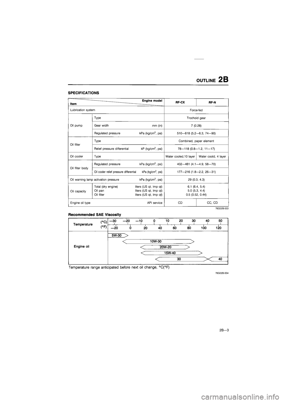
SPECIFICATIONS
Item Engine model RF-CX RF-N
Lubrication system Force-fed
Type Trochoid gear
Oil pump Gear width mm (in) 7 (0.28)
Regulated pressure kPa (kg/cm2,
psi)
510-618 (5.2 -6.3, 74—90)
Oil filter
Type Combined, paper element
Oil filter
Relief pressure differential kP (kg/cm2,
psi)
78-118 (0.8--1.2, 11-17)
Oil cooler Type Water cooled, 10 layer Water coold,
4
layer
Oil filter body
Regulated pressure kPa (kg/cm2,
psi)
402—481
(4.1
-4.9, 58—70)
Oil filter body
Oil cooler relief pressure differential kPa (kg/cm2, psi) 177-216 (1.8 -2.2, 26-31)
Oil warning lamp activation pressure kPa (kg/cm2,
psi)
29 (0.3, 4.3)
Oil capacity
Total (dry engine)
Oil pan
Oil filter
liters (US qt, Imp
qt)
liters (US qt, Imp
qt)
liters (US qt, Imp
qt)
6.1 (6.4, 5.4)
5.0 (5.3, 4.4)
0.5 (0.52, 0.44)
Engine oil type API service CD CC,
CD
76G02B-003
Recommended SAE Viscosity
CC) Temperature
—30 —20 —10 0 10 20 30 40 50 i i i i i i i ii CC) Temperature i i II i i i i —20 0 20 40 60 80 100 120
Engine oil
5W-30 >
Engine oil
< 10W-30 >
< 20W-20 >
< 15W-40 >
Engine oil
Engine oil
Temperature range anticipated before next oil change, °C(°F)
76G02B-004
2B-3
Page 330 of 1865

2B
ENGINE OIL, OIL
FILTER
86U02X-006
76G02B-010
86U02X-008
ENGINE OIL
REPLACEMENT
1. Warm up the engine to the normal operating tem-
perature and stop it.
2. Remove the oil filler cap and the oil pan drain plug.
3. Drain the oil into a suitable container.
Warning
Be careful when draining, the oil is very hot.
4. Install the drain plug and a new gasket.
Tightening torque:
29—41 N-m (3.0—4.2 m-kg, 22—30 ft-lb)
5. Refill the engine with the specified type and amount
of oil.
6. Refit the oil filler cap.
Oil pan capacity:
5.0 liters (5.3 US qt, 4.4 Imp qt)
7. Recheck the oil level after the engine has been run.
OIL
FILTER
REPLACEMENT
1. Remove the oil filter with a suitable wrench.
2. Use a clean rag to wipe off the mounting surface
on the engine.
3. Apply a coat of engine oil to the filter rubber seal.
4. Install the oil filter until the rubber seal contacts the
oil cooler by hand. Then tighten it a 7/6 turn fur-
ther with a band type wrench.
5. Start the engine and inspect around the filter seal
for leaks.
6. Check the oil level and add oil if necessary.
Oil filter capacity:
0.50 liters (0.52 US qt, 0.44 Imp qt)
76G02B-011
2B—6
Page 331 of 1865
OIL
COOLER AND
OIL
FILTER BODY 2B
OIL
COOLER AND
OIL
FILTER BODY
REMOVAL
1. Disconnect the battery negative cable.
2. Drain the engine oil and coolant.
3. Remove in the sequence shown in the figure.
76G02B-012
76G02B-013
1. Idler pulley
2. Water hose
3. Connector bolt
4. Oil cooler
5. Oil filter
6. Oil filter cover
7. Oil filter body
8. Plug
9. Pressure spring
10. Plunger control
11. Relief valve spring
12. Steel ball
INSPECTION
1. Inspect the oil cooler body for cracks or corrod-
ed. If necessary replace it.
2. Check the valves for damage or scoring if neces-
sary replace it.
3. Measure free length of each valve spring. If neces-
sary replace it.
Free length
Relief valve spring: 45.5 mm (1.79 in)
Pressure spring : 54.6 mm (2.15 in)
76G02B-014
2B-7
Page 332 of 1865

2B
OIL
COOLER AND
OIL
FILTER BODY
76G02B-015
76G02B-016
INSTALLATION
1. Apply a coat of engine oil to the valve holes.
2. Install the relief valve spring and pressure spring.
Tightening torque:
20—29 Nm (2.0—3.0 m-kg, 14—22 ft-lb)
3. Clean the contact surfaces of the cylinder block
and oil filter body.
4. Install new O-rings and apply a coat of engine oil.
5. Install the oil filter body.
Tightening torque:
Bolt A: 8—11 N-m
(80—110 cm-kg, 69—95 in-lb)
Bolt B: 37—52 N-m
(3.8—5.3 m-kg, 27—38 ft-lb)
76G02B-017
6. Apply a coat of engine oil to the O-rings.
7. Install the oil cooler with new O-ring on the con-
nector bolt.
Tightening torque:
25—34 N-m (2.5—3.5 m-kg, 18—25 ft-lb)
8. Connect the water hoses.
9. Install the oil filter cover.
Tightening torque:
8—11 N-m (80—110 cm-kg, 69—95 in-lb)
10. Install the oil filter. (Refer to page 2B—6)
11. Install the idler pulley.
Tightening torque:
19—26 N-m (1.9—2.6 m-kg, 14—19 ft-lb)
12. Install the Comprex supercharger drive belt and
adjust the belt deflection. (Refer to page 1C—7)
13. Add specified amount of coolant and engine oil.
14. Check for leaks.
76G02B-018
2B—8
Page 341 of 1865
3A OUTLINE
OUTLINE
COOLANT FLOW CHART (DOHC)
ISC solenoid valve 2-stage thermostat
From jo heater heater Main*™, valve ^--^Sub valve
76G03A-002
1. Water pump
2. Thermostat
3. Radiator
4. Coolant reservoir
5. Oil cooler
6. Cooling fan
3A—2
Page 342 of 1865
OUTLINE 3A
COOLANT FLOW CHART (SOHC)
76G03A-015
1. Water pump 4. Coolant reservoir
2. Thermostat 5. Oil cooler (8-valve...only ECE, 12-valve)
3. Radiator 6. Cooling fan
3A—3
Page 355 of 1865
3B OUTLINE
OUTLINE
COOLANT FLOW CHART
76G03B-002
1. Water pump 4. Coolant reservoir
2. Thermostat 5. CSD coolant passage
3. Radiator 6. Oil cooler
3B-2
Page 820 of 1865
7A REMOVAL
1. Remove the battery and battery carrier.
2. Disconnect the main fuse block. (Fl)
3. Disconnect the distributor lead.
4. Remove the air cleaner assembly.
76G07A-012
5. Remove the vacuum hose, the intercooler hose
(RF-CX) and the electric fan. (RF-N and RF-CX)
86U07A-021
8. Remove the front wheels.
9. Remove the splash shields.
10. Drain the transaxle oil.
86U07A-022
7A—14