Page 1134 of 1865
7C TROUBLESHOOTING
STEP 5 (OIL PRESSURE TEST)
This step determines line pressure, and governor pressure to check the hydraulic components and
for oil leakage.
Line Pressure Test
Preparation
1. Connect the SST to the line pressure output point.
2. Connect a tachometer to the engine.
3. Follow the test preparation procedure show in STEP 2 (STALL TEST).
Procedure
76G07C-030
1. Start the engine and verify that the idle speed is 950-5° rpm.
2. Shift the selector lever to D range.
3. Read the line pressure at idle.
4. Depress the brake pedal firmly with the left foot, and gradually depress the accelerator pedal with
the right foot.
5. Read the line pressure as soon as the engine speed becomes constant; then release the accelera-
tor pedal.
Caution
Steps 4 to 5 must be done within 5 seconds.
5. Shift the selector lever to N range and let the engine idle for one minute or more.
6. Read the line pressure at idle and engine stall speeds for each range in the same manner.
7C—20
Page 1139 of 1865
ON-VEHICLE MAINTENANCE 7C
ON-VEHICLE MAINTENANCE
AUTOMATIC TRANSAXLE FLUID (ATF)
Inspection for Fluid Leaks
Check for fluid leaks; the following figure shows the locations where fluid leakage may possibly occur.
1. Kick-down solenoid
2. Vacuum diaphragm
3. Manual shaft
4. Speedometer driven gear
5. Oil level tube
6. Governor cover
7. Governor
8. Oil pan
9. Oil pump
10. Inhibitor switch
11. Transaxle case
12. Oil pump
13. Square head plugs
14. Bearing cover
15. Drive shaft
76G07C-041
©
i
©
[JdQ©
I
Inspection of Level
1. Apply the parking brake and block the wheels to
prevent the vehicle from rolling.
Note
Place the car on a flat, level surface.
2. Run the engine so that the automatic transaxle fluid
reaches operating temperature.
3. While the engine is idling, shift the select lever from
P to 1 and back again.
4. Let the engine idle.
5.Shift the select lever to P.
76G07C-042
7C-25
Page 1141 of 1865

ON-VEHICLE MAINTENANCE 7C
76G07C-045
fflfiirv T
5. Turn locknut A by hand until it just touches the
spacer.
6. Tighten locknut B to the specified torque.
Tightening torque:
8—11 N-m (80—110 cm-kg, 69—95 in-lb)
7. Verify that there is a click at each range when shift-
ed from P «-» 1 range.
8. Check that the positions of the selector lever and
the indicator are exact.
9. Check that the button returns smoothly when used
to shift the selector.
10. If necessary, check the spring.
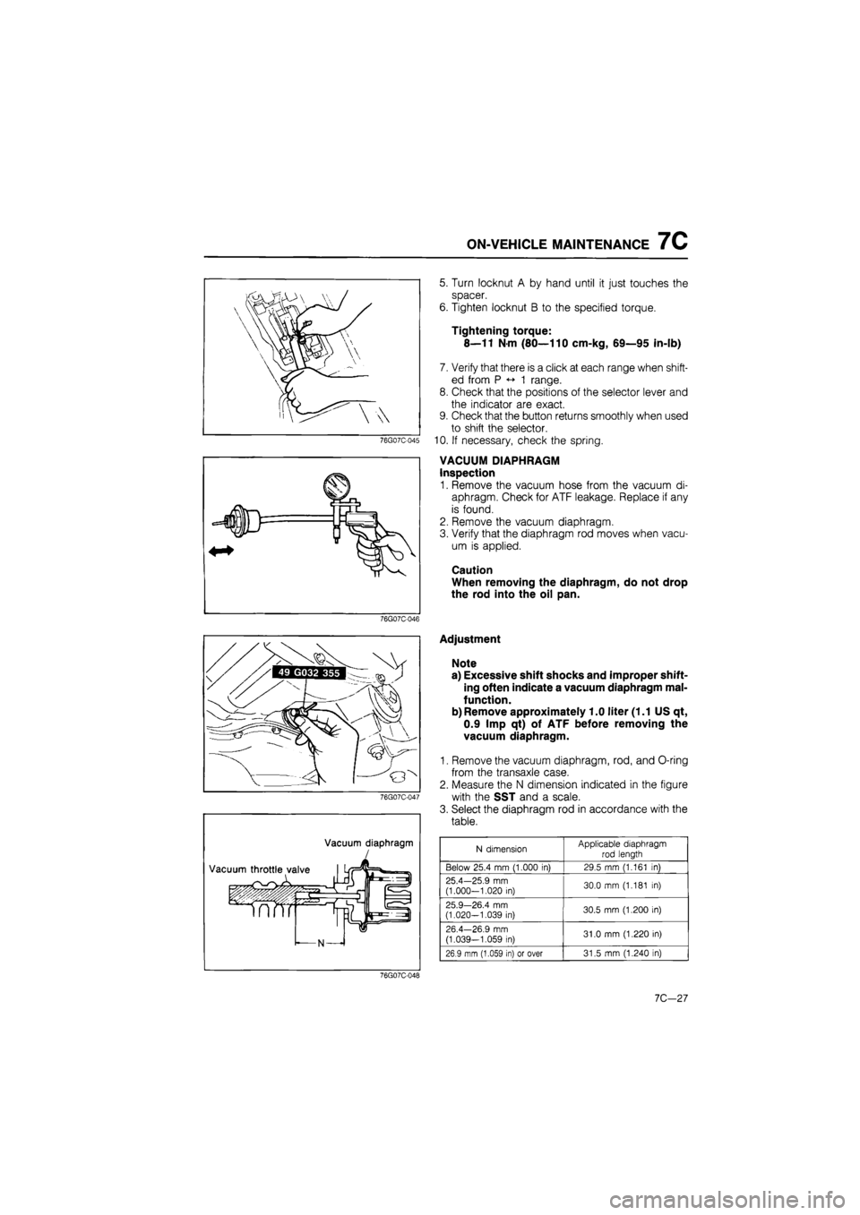
VACUUM DIAPHRAGM
Inspection
1. Remove the vacuum hose from the vacuum di-
aphragm. Check for ATF leakage. Replace if any
is found.
2. Remove the vacuum diaphragm.
3. Verify that the diaphragm rod moves when vacu-
um is applied.
Caution
When removing the diaphragm, do not drop
the rod into the oil pan.
76G07C-046
Vacuum diaphragm
Adjustment
Note
a) Excessive shift shocks and improper shift-
ing often indicate a vacuum diaphragm mal-
function.
b) Remove approximately 1.0 liter (1.1 US qt,
0.9 Imp qt) of ATF before removing the
vacuum diaphragm.
1. Remove the vacuum diaphragm, rod, and O-ring
from the transaxle case.
2. Measure the N dimension indicated in the figure
with the SST and a scale.
3. Select the diaphragm rod in accordance with the
table.
N dimension Applicable diaphragm
rod length
Below 25.4 mm (1.000 in) 29.5 mm (1.161 in)
25.4—25.9 mm (1.000-1.020 in) 30.0 mm (1.181 in)
25.9—26.4 mm (1.020-1.039 in) 30.5 mm (1.200 in)
26.4—26.9 mm
(1.039—1.059 in) 31.0 mm (1.220 in)
26.9 mm (1.059 in) or over 31.5 mm (1.240 in)
76G07C-048
10,-21
Page 1143 of 1865

ON-VEHICLE MAINTENANCE 7C
9. Install the under cover and side cover.
10. Lower the vehicle.
11. Add ATF, and with the engine idling, check the fluid
level.
12. Verify that there is no fluid leakage from the trans-
axle. (Refer to page 7C—25.)
76G07C-052
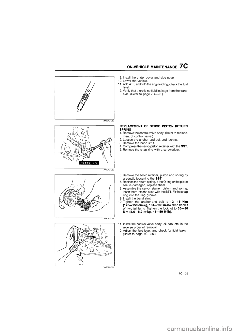
REPLACEMENT OF SERVO PISTON RETURN
SPRING
1. Remove the control valve body. (Refer to replace-
ment of control valve.)
2. Loosen the anchor end-bolt and locknut.
3. Remove the band strut.
4. Compress the servo piston retainer with the SST.
5. Remove the snap ring with a screwdriver.
76G07C-053
76G07C-054
6. Remove the servo retainer, piston and spring by
gradually loosening the SST.
7. Replace the return spring. If the O-ring or the piston
seal is damaged, replace them.
8. Assemble the servo retainer, piston, and spring,
insert them into the case with the SST. Fit the snap
ring into the ring groove.
9. Install the band strut.
10. Tighten the anchor-end bolt to 12—15 N-m
(120—150 cm-kg, 104—130 in-lb), then back it
off two full turns. Tighten the locknut to 55—80
N m (5.6—8.2 m-kg, 41—59 ft-lb).
11. Install the control valve body, oil pan, etc. in the
reverse order of removal.
12. Adjust the fluid level, and check for fluid leaks.
(Refer to page 7C—25.)
76G07C-055
7C—29
Page 1167 of 1865
DISASSEMBLY 7C
76G07C-126
76G07C-127
86U07B-169
-fct
„ 1 / V.
Bearing race
49 FT01 361
5. Remove the idle gear assembly and output gear
assembly by tapping out from the torque convert-
er side.
6. Remove the bearing cover.
(1) Remove the converter housing from the trans-
axle hanger.
(2) Remove the bearing cover bolts.
(3) Press the bearing cover assembly out of the
converter housing.
7. Press the bearing outer race out of the converter
housing with the SST.
Note
Install the bearing outer race during reassem-
bly to adjust the preload.
8. Check the oil seals for damage. Replace if
necessary.
76G07C-128
7C-53
Page 1168 of 1865

7C INSPECTION AND REPAIR
INSPECTION AND REPAIR
PRECAUTION
(1) Several of the parts resemble each other; organize them so that they do not get mixed up.
(2) Clean each part with cleaning oil, clean out the oil holes and oil passages with compressed air,
and check that there are no obstructions.
(3) When using cleaning oil and compressed air, wear protective eyewear.
(4) If a clutch plate or brake band is replaced with a new one, soak it in ATF for 2 hours or more
before installing.
(5) Before assembly, apply ATF to all seal rings, rotating parts, and sliding parts.
(6) All seals, gaskets and roll pins must be replaced with new ones during assembly.
(7) Use petroleum jelly, not grease where required.
(8) When it is necessary to replace a bushing, replace the assembly which includes that bushing.
76G07C-353
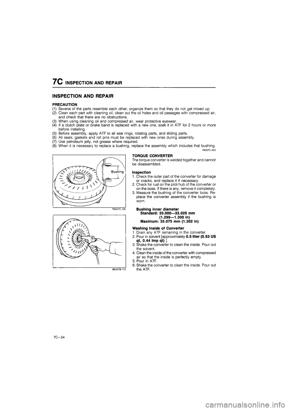
TORQUE CONVERTER
The torque converter is welded together and cannot
be disassembled.
Inspection
1. Check the outer part of the converter for damage
or cracks, and replace it if necessary.
2. Check for rust on the pilot hub of the converter or
on the boss. If there is any, remove it completely.
3. Measure the bushing of the converter boss. Re-
place the converter assembly if the bushing is
worn.
Bushing inner diameter
Standard: 33.000—33.025 mm
(1.299—1.300 in)
Maximum: 33.075 mm (1.302 in)
Washing Inside of Converter
1. Drain any ATF remaining in the converter.
2. Pour in solvent [approximately 0.5 liter (0.53 US
qt, 0.44 Imp qt) ].
3. Shake the converter to clean the inside. Pour out
the solvent.
4. Clean the inside of the converter with compressed
air so that the inside is perfectly empty.
5. Pour in ATF.
6. Shake the converter to clean the inside. Pour out
the ATF.
7C-54
Page 1169 of 1865
INSPECTION AND REPAIR 7C
OIL PUMP
Disassembly
Disassemble in the sequence shown in the figure, referring to the disassembly note for specially marked
parts.
76G07C-130 1. Seal ring
2. Seal ring
3. Pump cover
4. Pump flange
5. Inner gear
6. Outer gear
7. Pump housing
63U07B-089
Disassembly note
Inner gear and outer gear
Mark the inner and outer gears with paint before
removing them.
76G07C-131
Inspection
Check for the following and replace any faulty parts:
1. Damaged or worn inner or outer gear tooth
surfaces.
2. Broken or worn seal ring.
76G07C-132
7C—55
Page 1175 of 1865
INSPECTION AND REPAIR 7C
9. Check the front clutch operation.
(1) Set the clutch assembly onto the oil pump.
(2) Check the front clutch operation by applying
compressed air through the fluid passage
shown.
Air pressure:
392 kPa (4.0 kg/cm2, 57 psi) max.
Caution
Apply air for no more than 3 seconds.
76G07C-150
(3) Pour ATF into the front clutch until the clutch
piston is fully submerged.
76G07C-151
(4) Check that no bubbles come from between the
piston and drum seal while applying com-
pressed air through the fluid passage shown.
Air pressure:
392 kPa (4.0 kg/cm2, 57 psi) max.
Caution
Apply air for no more than 3 seconds.
76G07C-152
7C-61