Page 981 of 1865
INSPECTION AND REPAIR 7B
3. Remove one end of the snap ring from the groove
with snap ring pliers.
86U07B-194
4. Remove the SST from the reverse and forward
drum.
5. Remove the snap ring with a screw driver.
86U07B-195
6. Place the reverse and forward drum on the oil
pump.
7. Remove the reverse piston by applying com-
pressed air through the fluid passage.
86U07B-19G
86U07B-197
Inspection
Check the following and repair or replace any faulty
parts.
1. Drive and driven plates for damage or wear
Drive plate thickness
Standard: 1.6 mm (0.063 in)
Minimum: 1.4 mm (0.055 in)
2. Clutch piston for damage or cracks
3. Clutch drum for damage or deformation
4. Seal contact area for damage
5. Check ball for leaking sticking
6. Broken or worn snap ring
7. Broken or weakened spring
7B—115
Page 987 of 1865
INSPECTION AND REPAIR 7B
6. Check for the clutch operation as follows.
(1) Set the clutch assembly onto the oil pump.
(2) Check the clutch operation by applying com-
pressed air through the fluid passages as
shown.
Applied air pressure:
392 kPa (4.0 kg/cm2, 57 psi)
86U07B-217
(3) Pour in ATF so that the reverse piston, coast-
ing clutch drum, and coasting clutch piston are
fully submerged.
86U07B-218
(4) Check that no bubbles come from between the
piston and drum seal when applying com-
pressed air through the fluid passages as
shown.
Caution
The compressed air must be under 392 kPa
(4.0 kg/cm2, 57 psi), and should not applied
for over 3 seconds.
86U07B-219
7. Apply petroleum jelly to the thrust bearings to se-
cure them; then install them on both sides of the
reverse and forward drum.
Thrust bearing outer diameter
Oil pump side: 86.0 mm (3.39 in)
Small sun gear and one-way clutch side:
56.1 mm (2.21 in)
86U07B-220
7B-121
Page 1001 of 1865
INSPECTION AND REPAIR 7B
2-4 BRAKE BAND
Inspection
Check the following and replace if necessary.
1. Damaged or worn 2-4 brake band
86U07B-261
BAND SERVO
Inspection
Check the following and replace any faulty parts.
1. Damaged or worn piston
2. Weakened return spring
Free length of spring:
G4A-EL: 43.25 mm (1.703 in)
G4A-HL: FE engine 42.0 mm (1.654 in)
F8 engine 43.25 mm (1.703 in)
76G07B-140
OTHER INSPECTION
Check the following and replace any faulty parts.
1. Damaged or worn output shell
2. Damaged or worn internal gear
3. Damaged or worn turbine shaft
4. Damaged or worn oil pump shaft
5. Damaged or worn anchor strut and shaft
86U07B-263
6. Damaged or cracked valve body cover
7. Damaged or cracked oil pan
8. Damaged or clogged oil strainer
86U07B-264
7B—135
Page 1004 of 1865
7B INSPECTION AND REPAIR
3. Remove the 1-2 solenoid valve and 2-3 solenoid
valve and wire harness.
4. Remove the O-rings and oil strainers.
86U07B-268
5. Remove the front indicated bolts and pull out the
front control body with premain separator as a unit.
86U07B-269
86U07B-270
7. Remove the orifice check valve (<£0.8 mm, 0.071
in) and spring from the premain control body.
76G07B-142
7B—138
Page 1008 of 1865

7B INSPECTION AND REPAIR
Inspection
Check the following and replace any faulty parts.
1. Damaged or worn valves
2. Damaged oil passage
3. Cracked or damaged valve body
4. Operation of each valve
5. Weakened spring
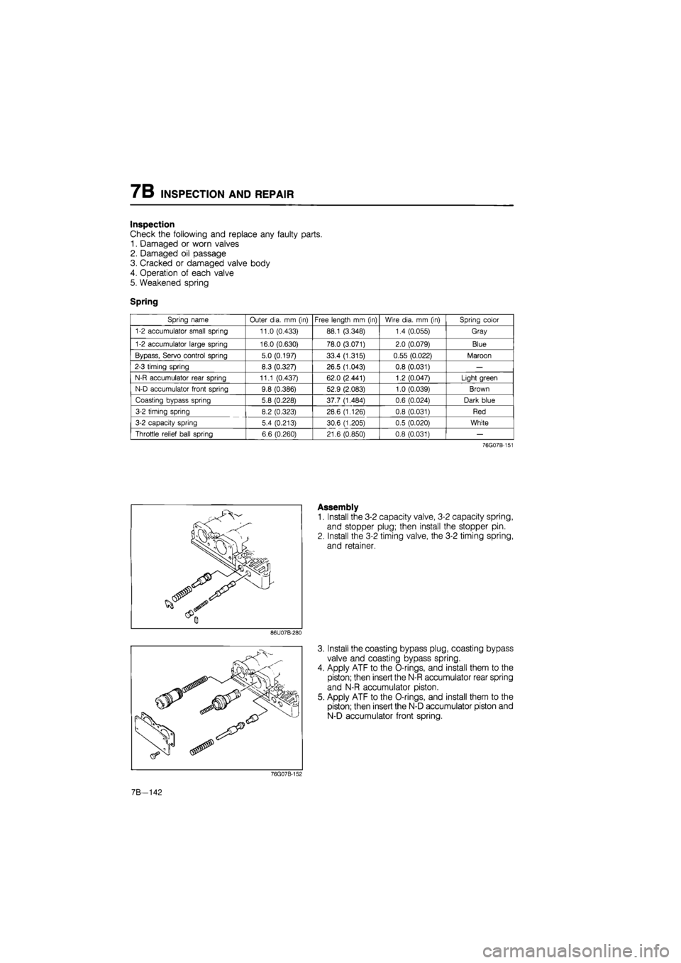
Spring
Spring name Outer dia.
mm
(in) Free length
mm
(in) Wire dia.
mm (in)
Spring color
1-2 accumulator small spring 11.0 (0.433) 88.1 (3.348) 1.4 (0.055) Gray
1-2 accumulator large spring 16.0 (0.630) 78.0 (3.071) 2.0 (0.079) Blue
Bypass, Servo control spring 5.0 (0.197) 33.4 (1.315) 0.55 (0.022) Maroon
2-3 timing spring 8.3 (0.327) 26.5 (1.043) 0.8 (0.031)
—
N-R accumulator rear spring 11.1 (0.437) 62.0 (2.441) 1.2 (0.047) Light green
N-D accumulator front spring 9.8 (0.386) 52.9 (2.083) 1.0 (0.039) Brown
Coasting bypass spring 5.8 (0.228) 37.7 (1.484) 0.6 (0.024) Dark blue
3-2 timing spring 8.2 (0.323) 28.6 (1.126) 0.8 (0.031) Red
3-2 capacity spring 5.4 (0.213) 30.6 (1.205) 0.5 (0.020) White
Throttle relief ball spring 6.6 (0.260) 21.6 (0.850) 0.8 (0.031)
—
76G07B-151
Assembly
1. Install the 3-2 capacity valve, 3-2 capacity spring,
and stopper plug; then install the stopper pin.
2. Install the 3-2 timing valve, the 3-2 timing spring,
and retainer.
86U07B-280
3. Install the coasting bypass plug, coasting bypass
valve and coasting bypass spring.
4. Apply ATF to the O-rings, and install them to the
piston; then insert the N-R accumulator rear spring
and N-R accumulator piston.
5. Apply ATF to the O-rings, and install them to the
piston; then insert the N-D accumulator piston and
N-D accumulator front spring.
76G07B-152
7B—142
Page 1011 of 1865

INSPECTION AND REPAIR 7B
Inspection
Check the following and replace any faulty parts.
1. Damaged or worn valves
2. Damaged oil passage
3. Cracked or damaged valve body
4. Operation of each valve
5. Weakened spring
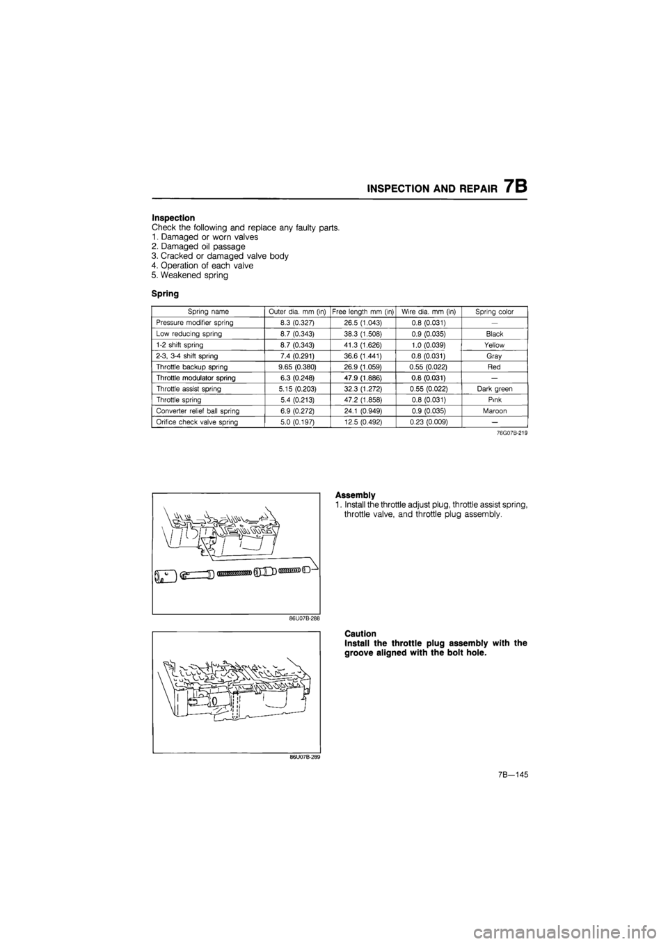
Spring
Spring name Outer dia.
mm
(in) Free length
mm (in)
Wire dia.
mm
(in) Spring color
Pressure modifier spring 8.3 (0.327) 26.5 (1.043) 0.8 (0.031)
—
Low reducing spring 8.7 (0.343) 38.3 (1.508) 0.9 (0.035) Black
1-2 shift spring 8.7 (0.343) 41.3 (1.626) 1.0 (0.039) Yellow
2-3, 3-4 shift spring 7.4 (0.291) 36.6 (1.441) 0.8 (0.031) Gray
Throttle backup spring 9.65 (0.380) 26.9 (1.059) 0.55 (0.022) Red
Throttle modulator spring 6.3 (0.248) 47.9 (1.886) 0.8 (0.031)
—
Throttle assist spring 5.15 (0.203) 32.3 (1.272) 0.55 (0.022) Dark green
Throttle spring 5.4 (0.213) 47.2 (1.858) 0.8 (0.031) Pink
Converter relief ball spring 6.9 (0.272) 24.1 (0.949) 0.9 (0.035) Maroon
Orifice check valve spring 5.0 (0.197) 12.5 (0.492) 0.23 (0.009)
—
76G07B-219
]
Assembly
1. Install the throttle adjust plug, throttle assist spring,
throttle valve, and throttle plug assembly.
86U07B-288
Caution
Install the throttle plug assembly with the
groove aligned with the bolt hole.
86U07B-289
7B-145
Page 1014 of 1865
7B INSPECTION AND REPAIR
Inspection
Check the following and replace any faulty parts.
1. Damaged or worn valves
2. Damaged oil passage
3. Cracked or damaged valve body
4. Operation of each valve
5. Weakened spring
Spring
Spring name Outer dia.
mm
(in) Free length
mm
(in) Wire dia.
mm (in)
Spring color
Pressure regulator spring 11.5 (0.453) 26.5 (1.043) 1.0 (0.039) Maroon
Lock-up control spring 5.0 (0.197) 35.2 (1.386) 0.6 (0.024) Purple
86U07B-295
Assembly
1. Install the lock-up control spring, lock-up control
valve, stopper plug, and stopper pin.
86U07B-296
Install the pressure regulator valve, pressure regu-
lator spring, pressure regulator spring seat, pres-
sure regulator plug, pressure regulator plug sleeve,
pressure regulator backup plug, stopper plug, and
stopper pin.
Note
Install the stopper plug larger end first.
86U07B-297
3. Install the manual valve.
86U07B-298
7B-148
Page 1025 of 1865
INSPECTION AND REPAIR 7B
13. Remove the orifice check valves (01.5 mm, 0.059
in) and springs, oil strainer, and rubber ball from
the main control body.
76G07B-164
7B-159