Page 1316 of 1865
1 0 STEERING GEAR AND LINKAGE
STEERING GEAR AND LINKAGE
STRUCTURAL VIEW
Manual steering
Power steering
1. Oil pressure switch connector
2. Pipes
3. Tie-rod end
4. Steering shaft universal joint
5. Mud flap
86U10X-051
10-28
Page 1332 of 1865
1 0 4-WHEEL STEERING GEAR AND LINKAGE
INSPECTION
Front Steering Gear and Linkage
1. Check the following and replace the front steering
gear assembly if necessary.
(a) Damaged or cracked case
(b) Bent linkage
86U10X-079
2. Check the following and replace any faulty parts.
(a) Clogged, bent, or pinched pipes
(b) Faulty oil pressure switch
(c) Damaged mounting bracket and mounting
rubber
(d) Cracked, damaged, or deteriorated boots
86U10X-080
Available spare parts
86U10X-081
1. Tie-rod end 7. Oil pressure switch
2. Tie-rod end boot 8. O-ring
3. Nut 9. Mounting bracket
4. Boot 10. Mounting rubber
5. Boot band (large) 11. Oil pipe
6. Boot band (small) 12. Steering gear assembly
10—44
Page 1346 of 1865

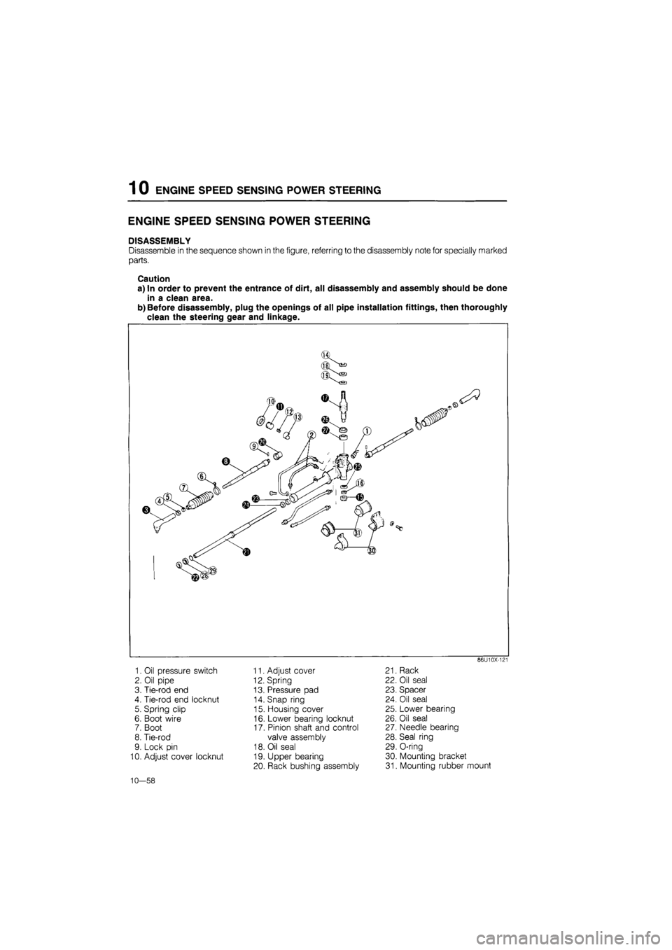
1 0 ENGINE SPEED SENSING POWER STEERING
ENGINE SPEED SENSING POWER STEERING
DISASSEMBLY
Disassemble in the sequence shown in the figure, referring to the disassembly note for specially marked
parts.
Caution
a) In order to prevent the entrance of dirt, all disassembly and assembly should be done
in a clean area.
b) Before disassembly, plug the openings of all pipe installation fittings, then thoroughly
clean the steering gear and linkage.
86U10X-121
1. Oil pressure switch
2. Oil pipe
3. Tie-rod end
4. Tie-rod end locknut
5. Spring clip
6. Boot wire
7. Boot
8. Tie-rod
9. Lock pin
10. Adjust cover locknut
11. Adjust cover
12. Spring
13. Pressure pad
14. Snap ring
15. Housing cover
16. Lower bearing locknut
17. Pinion shaft and control
valve assembly
18. Oil seal
19. Upper bearing
20. Rack bushing assembly
21. Rack
22. Oil seal
23. Spacer
24. Oil seal
25. Lower bearing
26. Oil seal
27. Needle bearing
28. Seal ring
29. O-ring
30. Mounting bracket
31. Mounting rubber mount
10—58
Page 1351 of 1865
ENGINE SPEED SENSING POWER STEERING 1 0
ccr
Oil pipe
Clogging or damage
86U10X-138
Tie-rod and tie-rod end
1. Tie-rod damage
2. Tie-rod ball joint damage and operation
3. Tie-rod end damage and operation
86U10X-139
Pressure pad and spring
1. Pressure pad damage
2. Spring damage
86U10X-140
I
vwmwmwjwmuwf
Rack
1. Rack cracking, damage, or wear of teeth
2. Seal ring holder wear or damage
3. Rack piston side corrosion
86U10X-141
10—63
Page 1362 of 1865
1 0 ENGINE SPEED SENSING POWER STEERING
Oil pressure switch
1. Install the pressure switch O-ring in the gear
housing.
2. Install the oil pressure switch.
Tightening torque:
31—36 N-m (3.2—3.7 m-kg, 23—27 ft-lb)
10—74
Page 1363 of 1865
ELECTRONICALLY-CONTROLLED POWER STEERING 1 0
ELECTRONICALLY-CONTROLLED POWER STEERING
DISASSEMBLY
Disassemble in the sequence shown in the figure, referring to the disassembly note for specially marked
parts.
Caution
a) Because adjustment of the spool valve is not possible, do not disassemble the gear box
for spool valve repairs. If repairs are necessary, replace the gear box assembly.
b) In order to prevent the entrance of dirt, all disassembly and assembly should be done
in a clean area.
c) Before disassembly, plug the openings of all pipe installation fittings; then thoroughly
clean the steering gear and linkage.
86U10X-180
1. Pipe
2. Solenoid valve
3. Tie-rod end
4. Tie-rod end locknut
5. Spring clip
6. Boot wire
7. Boot
8. Tie-rod
9. Adjust cover locknut
10. Adjust cover
11. Spring
12. Pressure pad
13. Outer box assembly
14. Oil seal
15. Mounting bracket
16. Mounting rubber
10—75
Page 1364 of 1865
1 0 ELECTRONICALLY-CONTROLLED POWER STEERING
Disassembly Note
Steering gear and linkage
Secure the mount part of the removed gear and link-
age in a vise.
Caution
Insert protective material (such as copper
plates) in the jaws of the vise.
86U10X-181
Tie-rod ends
Before removing the tie-rod ends, make a mark for
proper installation.
86U10X-182
Oil pipe
Mark the pressure and return pipes and the valve
case for proper installation. Remove the pipes.
86U10X-183
Solenoid valve
Remove the solenoid valve.
86U10X-184
10—76
Page 1366 of 1865
1 0 ELECTRONICALLY-CONTROLLED POWER STEERING
Oil seal
Remove the oil seal with a screwdriver.
86U10X-188
INSPECTION
Check the following and replace any faulty parts.
1. Cracked, damaged, or deteriorated boots
2. Worn pressure pad friction surface
3. Loose or sticking tie-rod ball joint
4. Bent or damaged tie-rod or tie-rod end
86U10X-189
5. Worn outer box bushing
86U10X-190
6. Cracked or damaged gear housing
7. Steering gear oil leakage
86! I10X-191
10-78