Page 1368 of 1865
1 0 ELECTRONICALLY-CONTROLLED POWER STEERING
2. Protect the outer box with cloth and tighten it with
a pipe wrench.
86U10X-193
3. Stake between the outer box and the rack hous-
ing with a center punch.
B6U10X-194
4. Install the oil seal with a suitable pipe.
86U10X-195
5. Install the pressure pad and spring in the gear
housing.
86U10X-196
10—80
Page 1370 of 1865
1 0 ELECTRONICALLY-CONTROLLED POWER STEERING
12. Stake the washer in two places with a punch.
86U10X-201
13. Install the boot. Wrap a new wire around it two
times and twist it 4 to 4.5 times.
Caution
Be sure that the boot is not twisted or dented.
86U10X-202
14. Install the tie-rod ends, aligning them with the marks
made before disassembly.
86U10X-203
15. Install the solenoid valve and pressure switch.
16. Align the oil pipes with the marks made before dis-
assembly, then tighten them.
86U10X-204
10—82
Page 1371 of 1865
OIL PUMP 1 0
OIL PUMP
REMOVAL AND INSTALLATION
1. Jack up the front of the vehicle, and support it with safety stands.
2. Remove in the order shown in the figure, referring to the removal note for specially marked parts.
3. Install in the reverse order of removal.
4. Tighten all nuts and bolts to the specified torque, referring to the figure.
Note
a) The power steering fluid will leak out when the return hose or the pressure hose is dis-
connected. Prepare a suitable container for it to drain into.
b) After installation, inspect the deflection of the oil pump belt and bleed the air from the
system, then check for fluid leakage. 2WS (Gasoline engine)
76G10X-041
4. Bracket
5. Oil pump
6. Oil pump pulley
1. Belt
2. Nut
3. Pipes
10—83
Page 1397 of 1865

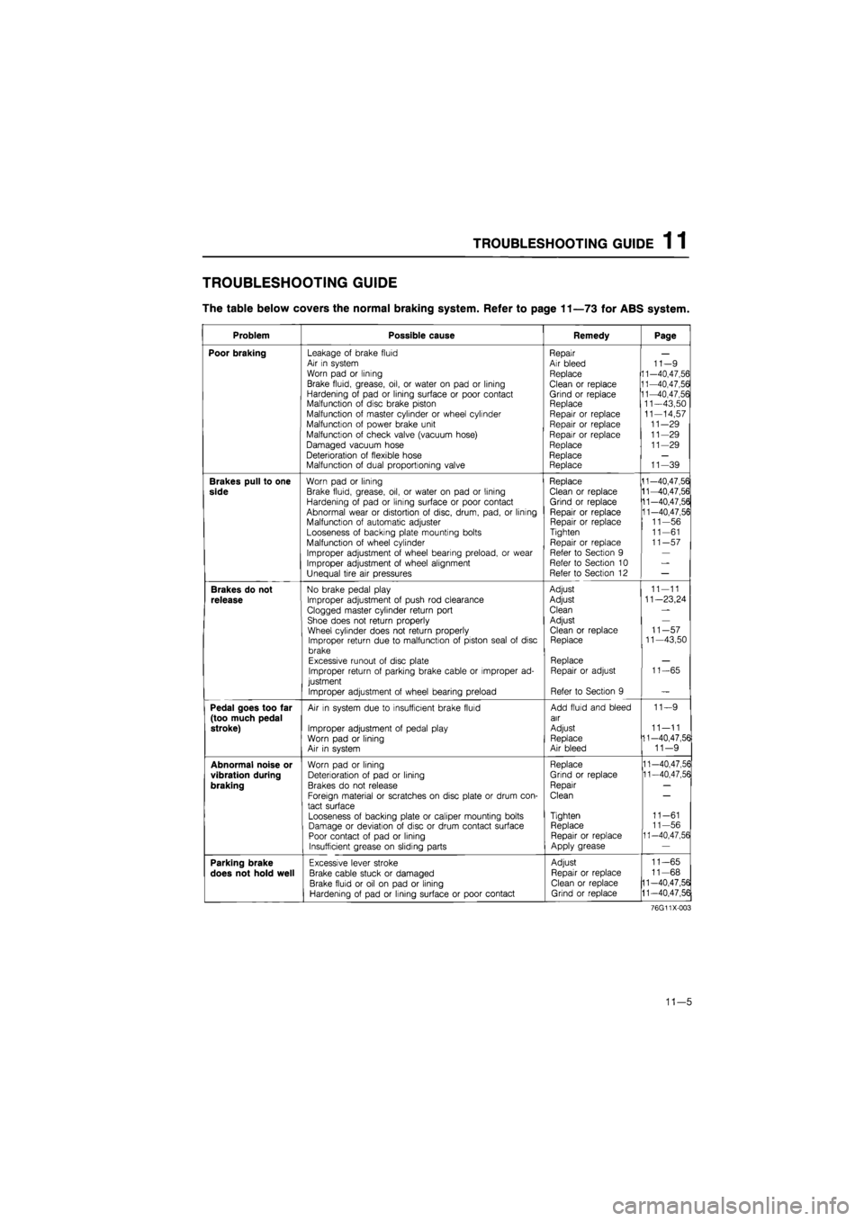
TROUBLESHOOTING GUIDE 1 1
TROUBLESHOOTING GUIDE
The table below covers the normal braking system. Refer to page 11—73 for ABS system.
Problem Possible cause Remedy Page
Poor braking Leakage of brake fluid Air in system Worn pad or lining
Brake fluid, grease, oil, or water on pad or lining Hardening of pad or lining surface or poor contact Malfunction of disc brake piston Malfunction of master cylinder or wheel cylinder Malfunction of power brake unit
Malfunction of check valve (vacuum hose)
Damaged vacuum hose Deterioration of flexible hose Malfunction of dual proportioning valve
Repair Air bleed Replace
Clean or replace Grind or replace Replace Repair or replace Repair or replace Repair or replace Replace Replace Replace
11-9 11-40,47,56 11-40,47,56 11-40,47,56 11—43,50 11-14,57 11-29 11-29 11-29
11-39
Brakes pull to one
side
Worn pad or lining
Brake fluid, grease, oil, or water on pad or lining Hardening of pad or lining surface or poor contact Abnormal wear or distortion of disc, drum, pad, or lining Malfunction of automatic adjuster Looseness of backing plate mounting bolts Malfunction of wheel cylinder
Improper adjustment of wheel bearing preload, or wear Improper adjustment of wheel alignment Unequal tire air pressures
Replace Clean or replace Grind or replace Repair or replace Repair or replace Tighten
Repair or replace Refer to Section 9 Refer to Section 10 Refer to Section 12
11-40,47,56 11-40,47,56 11-40,47,56 11-40,47,56 11-56 11-61 11-57
Brakes do not
release
No brake pedal play
Improper adjustment of push rod clearance
Clogged master cylinder return port Shoe does not return properly Wheel cylinder does not return properly Improper return due to malfunction of piston seal of disc brake Excessive runout of disc plate Improper return of parking brake cable or improper ad-justment
Improper adjustment of wheel bearing preload
Adjust
Adjust
Clean
Adjust Clean or replace Replace
Replace Repair or adjust
Refer to Section 9
11-11
11—23,24
11-57 11—43,50
11-65
Pedal goes too far (too much pedal stroke)
Air in system due to insufficient brake fluid
Improper adjustment of pedal play Worn pad or lining Air in system
Add fluid and bleed air
Adjust Replace Air bleed
11—9
11—11 11-40,47,56 11-9
Abnormal noise or
vibration during
braking
Worn pad or lining Deterioration of pad or lining Brakes do not release
Foreign material or scratches on disc plate or drum con-tact surface
Looseness of backing plate or caliper mounting bolts Damage or deviation of disc or drum contact surface Poor contact of pad or lining Insufficient grease on sliding parts
Replace
Grind or replace
Repair
Clean
Tighten Replace Repair or replace Apply grease
11-40,47,56 11-40,47,56
11-61 11-56 11-40,47,56
Parking brake
does not hold well
Excessive lever stroke
Brake cable stuck or damaged
Brake fluid or oil on pad or lining Hardening of pad or lining surface or poor contact
Adjust
Repair or replace Clean or replace Grind or replace
11-65
11-68
11-40,47,56
11-40,47,56
76G11X-003
11—5
Page 1501 of 1865

13 OUTLINE
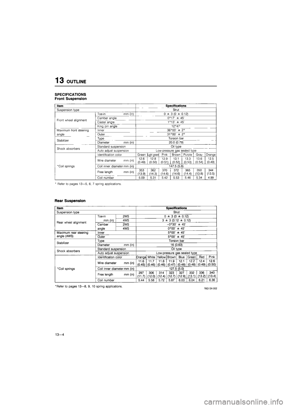
SPECIFICATIONS
Front Suspension
Item Specifications
Suspension type Strut
Toe-in mm (in) 0 ± 3 (0 ± 0.12)
Front wheel alignment Camber angle 0C 17' ± 45' Front wheel alignment Caster angle 1c 13' ± 45'
King pin angle 12°47'
Maximum front steering Inner 36 °00' ± 2°
angle Outer 31 °00' ± 2°
Stabilizer Type Torsion bar Stabilizer Diameter mm (in) 20.0 (0.79)
Shock absorbers Standard suspension Oil type Shock absorbers Auto adjust suspension Low-pressure gas sealed type
Identification color Green Light green Pink Brown Purple Gray Orange
Wire diameter mm (in) 12.6 (0.49) 12.8 (0.50)
12.9
(0.51) 13.1 (0.52)
13.3 (0.53)
13.6
(0.54) 12.5 (0.49)
*Coil springs Coil inner diameter mm (in) 147.5 (5.8)
Free length mm (in) 353 (13.9)
362 (14.3) 370 (14.6) 372 (14.6) 365 (14.4)
350
(13.8)
344
(13.5)
Coil number 5.09 5.31 5 42 5.53 5.46 5.34 4.99
* Refer to pages 13—5, 6, 7 spring applications.
Rear Suspension
Item Specifications
SusDension tvDe Strut
Rear wheel alignment
Toe-in
mm (in)
2WS 0 ± 3 (0 ± 0.12)
Rear wheel alignment
Toe-in
mm (in) 4WS 3 ± 3 (0.12 ± 0.12) Rear wheel alignment Camber
anale
2WS -0°30' ± 45' Rear wheel alignment Camber
anale 4WS 0°00' ± 45'
Maximum rear steering angle (4WS) Inner 5°00' ± 45' Maximum rear steering angle (4WS) Outer 5°00' ± 45'
Stabilizer TvDe Torsion bar Stabilizer Diameter mm (in) 16 (0.63)
Shock absorbers Standard susDension Oil tvDe Shock absorbers Auto adiust suspension Low-pressure c las sealed type
'Coil springs
Identification color Orange White Yellow Brown Blue Green Red Pink
'Coil springs
Wire diameter mm (in) 11.6
(0.45)
11.7 (0.46) 11.8
(0.46)
11.9 (0.47)
12.1
(0.48)
12.2
(0.48)
12.4 (0.49) 12.6 (0.50)
'Coil springs Coil inner diameter mm (in) 127.5 (5.0) 'Coil springs
Free length mm (in) 297 (11.7) 306 (12.0)
314 (12.4) 323 (12.7) 327 (12.9) 332 (13.1) 336 (13.21 340 (13.4)
'Coil springs
Coil number 5.44 5.58 5.72 5.87 6.03 6.04 6.21 6.36
'Refer to pages 13—8, 9, 10 spring applications.
13—4
Page 1508 of 1865

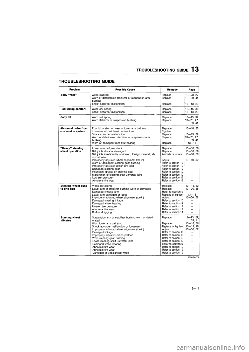
TROUBLESHOOTING GUIDE 1 3
TROUBLESHOOTING GUIDE
Problem Possible Cause Remedy Page
Body "rolls" Weak stabilizer Replace 13-23, 27 Worn or deteriorated stabilizer or suspension arm Replace 13—39, 41 bushing
Shock absorber malfunction Replace 13-13, 29
Poor riding comfort Weak coil spring Replace 13-15, 32 Shock absorber malfunction Replace 13-13. 29
Body tilt Worn coil spring Replace 13-15, 32 Worn stabilizer of suspension bushing Replace 13-23, 27,
39, 41
Abnormal noise from Poor lubrication or wear of lower arm ball joint Replace 13-18, 36 suspension system looseness of peripheral connections Tighten
Shock absorber malfunction Replace 13-13, 29 Worn or deteriorated stabilizer or suspension arm Replace 13—23, 27, bushing 39, 41 Worn or damaged front strut bearing Replace 13-15
"Heavy" steering Lower arm ball joint stuck Replace 13—18, 36
wheel operation Ball joints stuck or damaged Replace 13-18, 36
Ball joints insufficiently lubricated; foreign material; ab-Lubricate or replace 13-18, 36
normal wear Improperly adjusted wheel alignment (toe-in) Adjust 13-50, 52
Worn or damaged steering gear bushing Refer to section 10 —
Improperly adjusted pinion pre-load Refer to section 10 —
Damaged steering gear Refer to section 10 —
Insufficient grease on steering gear Refer to section 10 —
Malfunction of steering shaft universal joint Refer to section 10 —
Low tire pressure Refer to section 12 —
Abnormal tire wear Refer to section 12 —
Steering wheel pulls Weak coil spring Replace 13-15, 32
to one side Lower arm or stabilizer bushing worn or damaged Replace 13-20, 38
Damaged knuckle arm Refer to section 9 —
Lower arm damaged or loose Replace or tighten 13-18 Improperly adjusted wheel alignment (toe-in) Adjust 13-50, 52
Damaged steering linkage Refer to section 10 —
Damaged wheel bearing Refer to section 9 —
Uneven tire pressure Refer to section 12 —
Abnormal tire wear Refer to section 12 —
Brakes dragging Refer to section 11 —
Steering wheel Suspension arm or stabilizer bushing worn or deteri-Replace 13—23, 27.
vibrates orated 39, 41
Worn lower arm ball joint Replace 13-18, 36
Shock absorber malfunction or looseness Replace or tighten 13-13, 29
Improperly adjusted wheel alignment (toe-in) Adjust 13-50, 52 Damaged linkage Refer to section 10
Improperly adjusted pinion preload Refer to section 10
Worn steering gear bushing Refer to section 10 —
Loose steering shaft universal joint Refer to section 10 —
Damaged wheel bearing Refer to section 9 —
Abnormal tire wear Refer to section 12 —
Abnormal tire wear Refer to section 12 —
Damaged or unbalanced wheel Refer to section 12 —
76G13X-009
13—11
Page 1509 of 1865
1 3 TROUBLESHOOTING GUIDE
Problem Possible Cause Remedy Page
Excessive steering wheel play
Worn or damaged lower arm bushing
Improperly adjusted pinion preload
Worn rack and pinion
Loose steering shaft universal joint
Replace
Refer to section 10
Refer to section 10
Refer to section 10
13-20, 38
General instability Weak coil springs
Shock absorber malfunction Worn or damaged lower arm or stabilizer bushing
Improperly adjusted wheel alignment Improperly adjusted pinion preload
Loose steering shaft universal joint Incorrect tire pressure Damaged or unbalanced wheel Malfunction of wheel bearing
Replace Replace Replace Adjust
Refer to section 10 Refer to section 10 Refer to section 12 Refer to section 12 Refer to section 9
13-15, 32
13-13, 29
13-20, 38
13-50, 52
76G13X-009
13-12
Page 1690 of 1865
WARNING LIGHT AND SENDER 1 5
Washer Fluid Low Level Warning Light
76G15X-039
76G15X-040
Engine Oil Pressure Warning Light
76G15X-041
15—35