Page 590 of 1865

IDLE ADJUSTMENT 4C
Idle speed
Automatic
Control
Function
Engine Control Unit
IDLE
ADJUSTMENT
IDLE SPEED
The idle speed is controlled automatically by the
engine control unit through the idle speed con-
trol (ISC) solenoid valve, it is not necessary to
adjust the idle speed.
However, if the idle speed is not within specifi-
cation, the idle speed must be adjusted.
76G04C-044
Preparation
1) Check the condition of the engine (plugs, leaks in
hoses, etc.).
2) Make sure all accessories are OFF.
3) Warm up the engine and run it for three minutes
at 2,500—3,000 rpm in neutral.
4) Check the initial ignition timing and adjust it if
necessary.
76G04C-045
Inspection
1. Check that the idle speed is within specification
without grounding the test connector (Green,
1-pin).
Specification:
Applied load Idle speed
No load 750 ± 50 rpm
P/S load 750 ± 50 rpm
A/C and/or E/L load 800 ± 50 rpm
76G04C-046 2. If not correct, adjust the initial idle speed.
Adjustment
1. Ground the test connector (Green, 1-pin) with a
jumper wire.
2. Turn all accessories and loads OFF.
76G04C-047
4C—29
Page 611 of 1865

4C FUEL SYSTEM
COMPONENT DESCRIPTION
Component Function Remark
Air flow sensor Detects amount of intake air;
sends signal to engine control unit
Clutch switch Detects in-gear condition; sends signal to engine control unit Switch ON when clutch pedal released
Engine control unit Detects signals from input sensors and switches; controls injector and fuel pump operations
Fuel filter Filters fuel
Fuel pump Provides fuel to injectors • Operates while engine running
• Installed in fuel tank
Fuel pump control unit (4WS) Monitors fuel level in left section; controls transfer pump operation
G signal pick-up Detects No.1 cylinder TDC; sends signal to engine control unit Installed in distributor
Idle switch Detects when throttle valve fully closed; sends signal to engine control unit Installed on throttle body
Ignition switch (ST position) Sends engine cranking signal to engine control unit
Injector Injects fuel into intake port • Controlled by signals from engine control unit • High-ohmic injector
Intake air thermo sensor Detects intake air temperature; send signal to engine control unit
Control relay Supplies electric current to injectors fuel pump and engine control unit
Ne signal pick-up Detects crank angle at 180° intervals; sends signal to engine control unit Installed in distributor
Neutral switch Detects in-gear condition; sends signal to engine control unit
Switch ON when in gear
Oxygen sensor (Unleaded fuel) Detects oxygen concentration; sends signal to engine control unit
• Zirconia ceramic and platinum coating • Integrated heater coil
Pressure regulator Adjusts fuel pressure supplied to injectors
Pulsation damper Absorbs fuel pulsation
Throttle sensor Detects throttle valve opening angle;
sends signal to engine control unit
Installed on throttle body
Transfer pump (4WS) Pumps fuel from the left to the right side Controlled by fuel pump control unit
Transfer pump switch (4WS) Detects fuel level in left section;
sends signal to control unit
Water thermo sensor Detects coolant temperature; sends signal to engine control unit
Water thermo switch (Unleaded fuel) Detects radiator coolant temperature; sends signal to engine control unit ON: above 17°C (63°F)
76G04C-088
4C-50
Page 613 of 1865
4C FUEL SYSTEM
FUEL PRESSURE RELEASE AND SERVICING
FUEL SYSTEM
Fuel in the fuel system remains under high pressure
even when the engine is not running.
a) Before disconnecting any fuel line, release the fuel
pressure from the fuel system to reduce the pos-
sibility of injury or fire.
1. Start the engine.
2. Disconnect the 4-pin connector from the con-
trol relay or the fuel pump connector (5-pin or
6-pin).
3. After the engine stalls, turn OFF the ignition
switch.
4. Reconnect the relay or fuel pump connector.
b) Use a rag as protection from fuel spray when dis-
connecting the hoses.
Plug the hoses after removal.
c) When inspecting the fuel system, use the SST.
4C—52
Page 615 of 1865

4C FUEL SYSTEM
f-|To pulsation
-'damper
76G04C-092
Pressure regulator
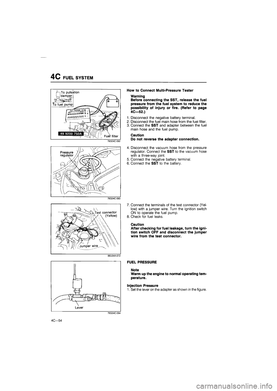
How to Connect Multi-Pressure Tester
Warning
Before connecting the SST, release the fuel
pressure from the fuel system to reduce the
possibility of injury or fire. (Refer to page
4C—52.)
1. Disconnect the negative battery terminal.
2. Disconnect the fuel main hose from the fuel filter.
3. Connect the SST and adapter between the fuel
main hose and the fuel pump.
Caution
Do not reverse the adapter connection.
4. Disconnect the vacuum hose from the pressure
regulator. Connect the SST to the vacuum hose
with a three-way joint.
5. Connect the negative battery terminal.
6. Connect the SST to the battery.
76G04C-093
V „ Test connector (Yellow)
7. Connect the terminals of the test connector (Yel-
low) with a jumper wire. Turn the ignition switch
ON to operate the fuel pump.
8. Check for fuel leaks.
Caution
After checking for fuel leakage, turn the igni-
tion switch OFF and disconnect the jumper
wire from the test connector.
86U04A-072
FUEL PRESSURE
Note
Warm up the engine to normal operating tem-
perature.
Injection Pressure
1. Set the lever on the adapter as shown in the figure.
76G04C-094
4C-54
Page 616 of 1865

FUEL SYSTEM 4C
i i 1 1 1 i i
r.:.:::r t t t t t izn —i—i—i—i—i—i—i—i—
2DD 350
86U04A-074
2. Run the engine and measure the injection pres-
sure at various speeds.
Injection pressure: Approx. 235—275 kPa
(2.4—2.8 kg/cm2, 34—40 psi)
3. If not within specification, check the fuel pump pres-
sure and fuel line pressure.
Fuel Pump Pressure
1. Connect the terminals of the test connector (Yel-
low) with a jumper wire.
2. Turn the ignition switch ON to operate the fuel
pump.
3. Set the lever on the adapter as shown in the figure.
4. Check the fuel pump pressure.
Fuel pump pressure: 441—588 kPa
(4.5—6.0 kg/cm2, 64—85 psi)
5. If the fuel pump pressure is not within specifica-
tion, check the following;
No pressure
• Fuel pump operation (Refer to page
4C—56.)
Low pressure
• Fuel pump feeding capacity (Refer to
page 4C—56.)
High pressure
• Replace the fuel pump
6. After checking the fuel pump pressure, disconnect
the jumper wire from the test connector.
Fuel Line Pressure
1. Start the engine and run it idle.
2. Set the lever on the adapter as shown in the figure.
3. Check the fuel line pressure.
Fuel line pressure: Approx. 186—226 kPa
(1.9—2.3 kg/cm2, 27—33 psi)
4. If not within specification, check the pressure regu-
lator vacuum hose.
4C-55
Page 617 of 1865

4C FUEL SYSTEM
86U04A-078
76G04C-097
76G04C-098
„\W cLTest connector (Yellow)
'-/jumper wire \\ \ •
5. Disconnect the vacuum hose from pressure regu-
lator, and place a finger over the end of the hose.
6. Check the fuel line pressure.
Fuel line pressure: 235—275 kPa
(2.4—2.8 kg/cm2, 34—40 psi)
7. If not within specification, replace the pressure
regulator.
8. Connect the vacuum hose to pressure regulator.
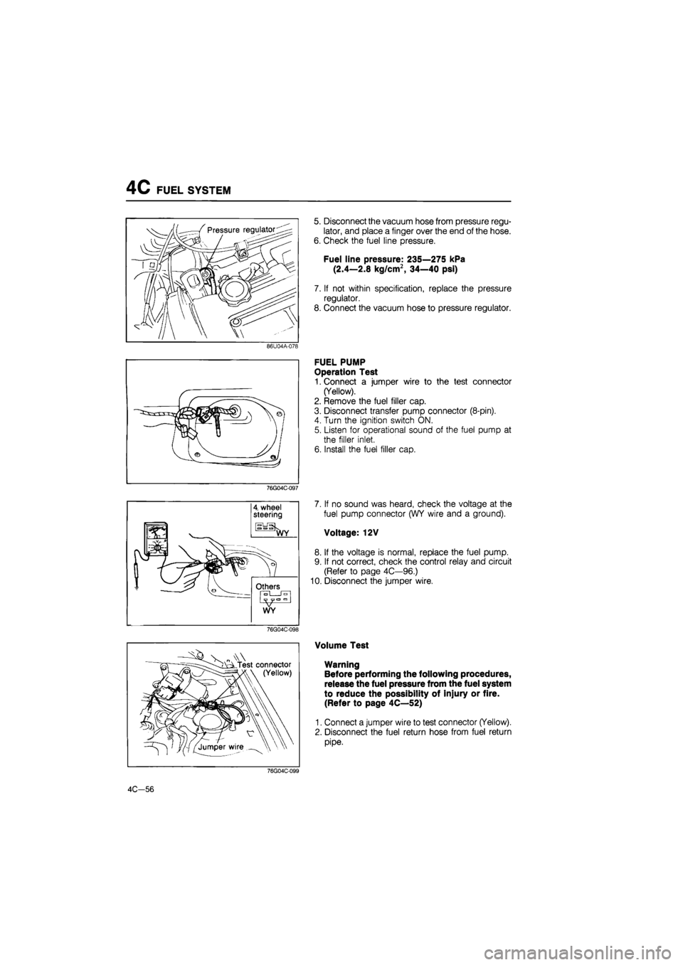
FUEL PUMP
Operation Test
1. Connect a jumper wire to the test connector
(Yellow).
2. Remove the fuel filler cap.
3. Disconnect transfer pump connector (8-pin).
4. Turn the ignition switch ON.
5. Listen for operational sound of the fuel pump at
the filler inlet.
6. Install the fuel filler cap.
7. If no sound was heard, check the voltage at the
fuel pump connector (WY wire and a ground).
Voltage: 12V
8. If the voltage is normal, replace the fuel pump.
9. If not correct, check the control relay and circuit
(Refer to page 4C—96.)
10. Disconnect the jumper wire.
Volume Test
Warning
Before performing the following procedures,
release the fuel pressure from the fuel system
to reduce the possibility of injury or fire.
(Refer to page 4C—52)
1. Connect a jumper wire to test connector (Yellow).
2. Disconnect the fuel return hose from fuel return
pipe.
76G04C-099
4C-56
Page 618 of 1865
FUEL SYSTEM 4C
Pulsation damper
76G04C-100
Intake mainfold
3. Turn the ignition switch ON for 10 seconds, and
check the feeding capacity with graduated
cylinder.
Feeding capacity:
Minimum 220 cc (13.4 cu in)/10 sec.
4. If not within specification, check the fuel filter, fuel
lines and fuel pump.
5. Turn the ignition switch OFF and disconnect the
jumper wire.
PULSATION DAMPER
1. Run the engine at idle.
2. Place a finger on the screw of the pulsation damper
head.
3. Check that pulsation is felt.
86U04A-083
Injector
INJECTOR
On-vehicle Inspection
1. Warm up the engine and run it at idle.
2. Listen for operational sound of the injector with a
screwdriver or a sound scope.
76G04C-101
3. Ground the test connector (Green, 1-pin).
76G04C-102
4C-57
Page 619 of 1865

4C FUEL SYSTEM
76G04C-103
76G04C-104
76G04C-105
- s A Test connector I \ (Yellow)
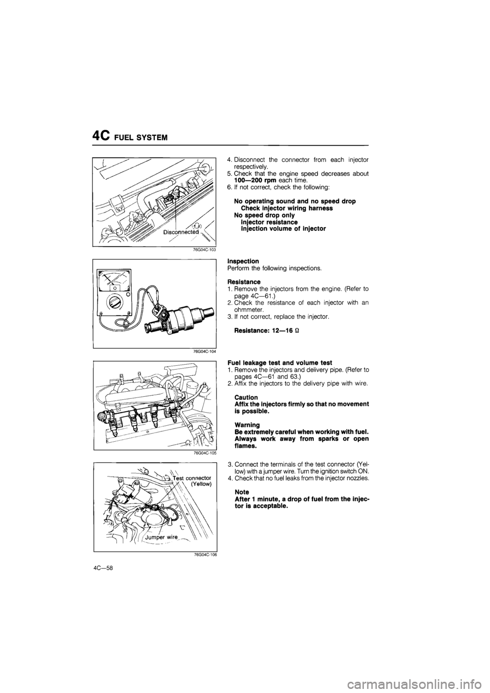
4. Disconnect the connector from each injector
respectively.
5. Check that the engine speed decreases about
100—200 rpm each time.
6. If not correct, check the following:
No operating sound and no speed drop
Check injector wiring harness
No speed drop only
Injector resistance
Injection volume of injector
Inspection
Perform the following inspections.
Resistance
1. Remove the injectors from the engine. (Refer to
page 4C—61.)
2. Check the resistance of each injector with an
ohmmeter.
3. If not correct, replace the injector.
Resistance: 12—16 Q
Fuel leakage test and volume test
1. Remove the injectors and delivery pipe. (Refer to
pages 4C—61 and 63.)
2. Affix the injectors to the delivery pipe with wire.
Caution
Affix the injectors firmly so that no movement
is possible.
Warning
Be extremely careful when working with fuel.
Always work away from sparks or open
flames.
3. Connect the terminals of the test connector (Yel-
low) with a jumper wire. Turn the ignition switch ON.
4. Check that no fuel leaks from the injector nozzles.
Note
After 1 minute, a drop of fuel from the injec-
tor is acceptable.
76G04C-106
4C—58