Page 272 of 878

MAF METER INSPECTION
1. INSPECT MAF METER RESISTANCE
Using an ohmmeter, measure the resistance between termi-
nals THA and E2.
�������� �
������� ��������
Between
terminals�������� �
������� ��������Resistance
�������� �
������� ��������Temperature
�������� ��������THA±E2�������� ��������10±20 k��������� ��������±20°C (±4°F)
�������� ��������THA±E2�������� ��������4±7 k��������� ��������0°C (32°F)
�������� ��������THA±E2�������� ��������2±3 k��������� ��������20°C (68°F)�������� ��������THA±E2�������� ��������0.9±1.3 k��������� ��������40°C (104°F)�������� ��������THA±E2�������� ��������0.4±0.7 k��������� ��������60°C (140°F)
If the resistance is not as specified, replace the MAF meter.
2. INSPECT MAF METER OPERATION
(a) Connect the MAF meter connector.
(b) Connect the negative (±) terminal cable to the battery.
(c) Using a voltmeter, connect the positive (+) tester probe to
terminal VG, and negative (±) tester probe to terminal E21.
(d) Turn the ignition switch ON.
(e) Blow air into the MAF meter, and check that the voltage
fluctuates.
If operation is not as specified, replace the MAF meter.
(f) Turn the ignition switch OFF.
(g) Disconnect the negative (±) terminal cable from the battery.
(h) Disconnect the MAF meter connector. EG±288
± ENGINESFI SYSTEM (2JZ±GTE)
Page 281 of 878
IAC VALVE REMOVAL
1. DRAIN ENGINE COOLANT
2. DISCONNECT IAC VAVE CONNECTOR
3. REMOVE IAC VALVE
(a) Remove the 2 bolts, and disconnect the IAC valve from the
air intake chamber.
(b) Remove the gasket.
(c) Disconnect these hoses from the IAC valve, and remove the
IAC valve:
(1) Air hose
(2) Water bypass hose (from No.2 water bypass pipe)
(3) Water bypass hose (from No.4 water bypass pipe)
(d) Remove the seal washer and check valve.
IAC VALVE INSPECTION
INSPECT IAC VALVE OPERATION
(a) Apply battery voltage to terminals B1 and B2, and while
repeatedly grounding S1±S2±S3±S4±S 1 in sequence, and
check that the valve moves toward the closed position.
(b) Apply battery voltage to terminals B1 and B2, and while
repeatedly grounding S4±S3±S2±S1±S 4 in sequence,
check that the valve moves toward the open position.
If operation is not as specified, replace the IAC valve.
± ENGINESFI SYSTEM (2JZ±GTE)EG±297
Page 282 of 878
 Install the check valve and seal washer.
NOTICE: Be careful of the check valve and seal washer instal-
lation direction.
(b) Connect these hoses:
wAir")
IAC VALVE INSTALLATION
1. INSTALL IAC VALVE
(a) Install the check valve and seal washer.
NOTICE: Be careful of the check valve and seal washer instal-
lation direction.
(b) Connect these hoses:
wAir hose
wWater bypass hose (from No.2 water bypass pipe)
wWater bypass hose (from No.4 water bypass pipe)
(c) Install a new gasket and the IAC valve with the 2 bolts.
Torque: 21 NVm (210 kgfVcm, 15 ftVlbf)
2. CONNECT IAC VALVE CONNECTOR
3. FILL WITH ENGINE COOLANT
EFI MAIN RELAY
EFI MAIN RELAY INSPECTION
1. REMOVE EFI MAIN RELAY
LOCATION: In the engine compartment relay box.
2. INSPECT EFI MAIN RELAY
A. Inspect relay continuity
(a) Using an ohmmeter, check that there is continuity between
terminals 1 and 2.
(b) Check that there is no continuity between terminals 3 and 5.
If continuity is not as specified, replace the relay.
B. Inspect relay operation
(a) Apply battery voltage across terminals 1 and 2.
(b) Using an ohmmeter, check that there is continuity between
terminals 3 and 5.
If operation is not as specified, replace the relay.
3. REINSTALL EFI MAIN RELAY EG±298
± ENGINESFI SYSTEM (2JZ±GTE)
Page 283 of 878
EFI NO.2 RELAY
EFI NO.2 RELAY INSPECTION
1. REMOVE EFI NO.2 RELAY
LOCATION: In the engine compartment relay box.
2. INSPECT EFI NO.2 RELAY
A. Inspect relay continuity
(a) Using an ohmmeter, check that there is continuity between
terminals 1 and 2.
(b) Check that there is no continuity between terminals 3 and 5.
If continuity is not as specified, replace the relay.
B. Inspect relay operation
(a) Apply battery voltage across terminals 1 and 2.
(b) Using an ohmmeter, check that there is continuity between
terminals 3 and 5.
If operation is not as specified, replace the relay.
3. REINSTALL EFI NO.2 RELAY
± ENGINESFI SYSTEM (2JZ±GTE)EG±299
Page 286 of 878
C. Inspect VSV operation
(a) Check that air flows from port E to G.
(b) Apply battery voltage across the terminals.
(c) Check that air flows from port E to the filter.
If operation is not as specified, replace the VSV.
3. REINSTALL VSV
VSV FOR INTAKE AIR CONTROL VALVE
COMPONENTS FOR REMOVAL AND
INSTALLATION
EG±302± ENGINESFI SYSTEM (2JZ±GTE)
Page 287 of 878
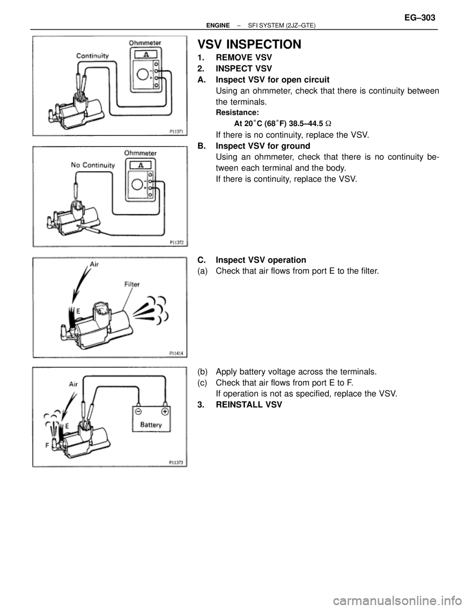
VSV INSPECTION
1. REMOVE VSV
2. INSPECT VSV
A. Inspect VSV for open circuit
Using an ohmmeter, check that there is continuity between
the terminals.
Resistance:
At 20°C (68°F) 38.5±44.5 �
If there is no continuity, replace the VSV.
B. Inspect VSV for ground
Using an ohmmeter, check that there is no continuity be-
tween each terminal and the body.
If there is continuity, replace the VSV.
C. Inspect VSV operation
(a) Check that air flows from port E to the filter.
(b) Apply battery voltage across the terminals.
(c) Check that air flows from port E to F.
If operation is not as specified, replace the VSV.
3. REINSTALL VSV
± ENGINESFI SYSTEM (2JZ±GTE)EG±303
Page 289 of 878
C. Inspect VSV operation
(a) Check that air does not flow from port E to F.
(b) Apply battery voltage across the terminals.
(c) Check that air flows from port E to F.
If operation is not as specified, replace the VSV.
3. REINSTALL VSV ASSEMBLY
VSV FOR EXHAUST GAS CONTROL
VA LV E
COMPONENTS FOR REMOVAL AND
INSTALLATION
± ENGINESFI SYSTEM (2JZ±GTE)EG±305
Page 290 of 878
VSV INSPECTION
1. REMOVE VSV ASSEMBLY
2. INSPECT VSV
A. Inspect VSV for open circuit
Using an ohmmeter, check that there is continuity between
the terminals.
Resistance:
At 20°C (68°F) 38.5±44.5 �
If there is no continuity, replace the VSV.
B. Inspect VSV for ground
Using an ohmmeter, check that there is no continuity be-
tween each terminal and the body.
If there is continuity, replace the VSV.
C. Inspect VSV operation
(a) Check that air flows from port E to the filter.
(b) Apply battery voltage across the terminals.
(c) Check that air flows from port E to F.
If operation is not as specified, replace the VSV.
3. REINSTALL VSV ASSEMBLY EG±306
± ENGINESFI SYSTEM (2JZ±GTE)
 Remove the 2 bolts, and disconnect the IAC valve from the
air intake chamber.
(b) Remove the gas")
 Using an ohmmeter, check")
 Check that air flows from port E to G.
(b) Apply battery voltage across the terminals.
(c) Check that air flows from port E to the filter.
If operation is not as speci")
 Check that air does not flow from port E to F.
(b) Apply battery voltage across the terminals.
(c) Check that air flows from port E to F.
If operation is not as specif")
 38.5±44.5")