Page 203 of 878

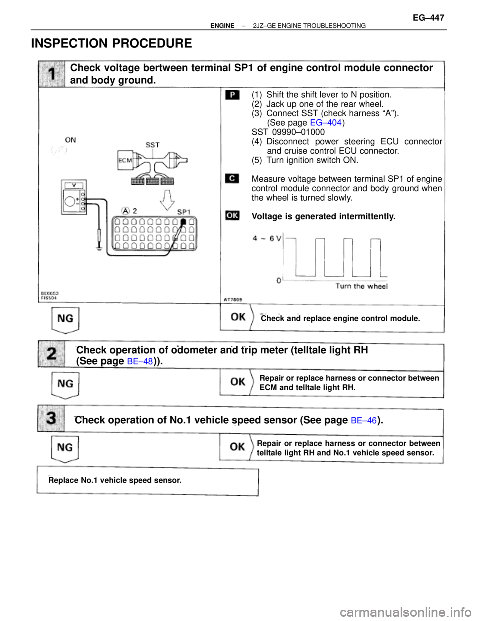
INSPECTION PROCEDURE
(See page
EG±404)
(See page BE±48)).
Check voltage bertween terminal SP1 of engine control module connector
and body ground.
Check and replace engine control module.
(1) Shift the shift lever to N position.
(2) Jack up one of the rear wheel.
(3) Connect SST (check harness ªAº).
(See page EG±404)
SST 09990±01000
(4) Disconnect power steering ECU connector
and cruise control ECU connector.
(5) Turn ignition switch ON.
Measure voltage between terminal SP1 of engine
control module connector and body ground when
the wheel is turned slowly.
Voltage is generated intermittently.
Repair or replace harness or connector between
ECM and telltale light RH.
Check operation of odometer and trip meter (telltale light RH
(See page
BE±48)).
Check operation of No.1 vehicle speed sensor (See page BE±46).
Replace No.1 vehicle speed sensor.
Repair or replace harness or connector between
telltale light RH and No.1 vehicle speed sensor.
± ENGINE2JZ±GE ENGINE TROUBLESHOOTINGEG±447
Page 250 of 878
COMPONENTS FOR REMOVAL AND
INSTALLATION
FUEL PUMP REMOVAL
CAUTION: Do not smoke or work near an open flame when
working on the fuel pump.
1. TAKE OUT FLOOR CARPET
2. REMOVE SPARE WHEEL COVER
3. REMOVE SPARE WHEEL
4. REMOVE SERVICE HOLE COVER EG±266
± ENGINESFI SYSTEM (2JZ±GTE)
Page 254 of 878
(e) Temporarily install the retainer.
(f) Using SST, tighten the retainer until the arrow mark on
retainer is within the lines on the fuel tank.
SST 09808±14010
(g) Check that the arrow marks of the fuel pump bracket and fuel
tank are aligned.
(h) Install the retainer clamp.
(i) Connect the connector and hoses to the fuel pump bracket:
wFuel pump connector
wFuel outlet hose
Connect the outlet hose with 2 new gaskets and the union
bolt.
Torque: 29 NVm (300 kgfVcm, 22 ftVlbf)
wFuel return hose
wFuel breather hose
2. INSTALL SERVICE HOLE COVER
3. INSTALL SPARE WHEEL
4. INSTALL SPARE WHEEL COVER
5. INSTALL FLOOR CARPET
6. CHECK FOR FUEL LEAKS
(See item 5 in fuel system in precaution) EG±270
± ENGINESFI SYSTEM (2JZ±GTE)
Page 321 of 878
COMPONENTS FOR REMOVAL AND
INSTALLATION
FUEL PUMP REMOVAL
CAUTION: Do not smoke or work near an open flame when
working on the fuel pump.
1. TAKE OUT FLOOR CARPET
2. REMOVE SPARE WHEEL COVER
3. REMOVE SPARE WHEEL
4. REMOVE SERVICE HOLE COVER
± ENGINESFI SYSTEM (2JZ±GE)EG±195
Page 325 of 878
(g) Install the retainer clamp.
(h) Connect the connector and hoses to the fuel pump bracket:
wFuel pump connector
wFuel outlet hose
Connect the outlet hose with 2 new gaskets and the union
bolt.
Torque: 29 NVm (300 kgfVcm, 22 ftVlbf)
wFuel return hose
wFuel breather hose
2. REMOVE SERVICE HOLE COVER
3. REMOVE SPARE WHEEL
4. REMOVE SPARE WHEEL COVER
5. TAKE OUT FLOOR CARPET
6. CHECK FOR FUEL LEAKS
(See item 5 in fuel system in precaution)
± ENGINESFI SYSTEM (2JZ±GE)EG±199
Page 478 of 878
6. 2JZ±GTE M/T:
REMOVE CLUTCH COVER SET BOLTS
(a) Remove the 2 bolts and service hole cover.
(b) Place the matchmarks on the flywheel and clutch cover.
(c) Remove the 6 bolts.
7. A/T:
REMOVE TORQUE CONVERTER CLUTCH MOUNTING
BOLTS
(a) Remove the hole plug.
(b) Turn the crankshaft to gain access to each bolt.
Remove the 6 bolts.
8. SEPARATE ENGINE AND TRANSMISSION
Remove the 6 bolts and transmission.
HINT: The º17º is 17 mm head bolt, and º14º is 14 mm head
bolt.
9. 2JZ±GE M/T:
REMOVE CLUTCH COVER AND DISC
(a) Place matchmarks on the flywheel and clutch cover.
(b) Loosen each bolt one turn at a time until spring tension is
released.
(c) Remove the bolts, and pull off the clutch cover with the clutch
disc.
NOTICE: Do not drop the clutch disc.
± ENGINEENGINE MECHANICALEG±95
Page 481 of 878
PREPARATION FOR DISASSEMBLY
1. M/T:
REMOVE FLYWHEEL
2. A/T:
REMOVE DRIVE PLATE
3. INSTALL ENGINE TO ENGINE STAND FOR
DISASSEMBLY
4. REMOVE GENERATOR
5. REMOVE TIMING BELT AND PULLEYS
(See timing belt removal)
6. REMOVE CYLINDER HEAD
(See cylinder head removal)
7. REMOVE OIL FILTER
(See oil and filter replacement in Lubrication System)
8. 2JZ±GTE:
REMOVE OIL COOLER
(See oil cooler removal in Lubrication System)
9. REMOVE NO.2 WATER BYPASS PIPE
(a) 2JZ±GE:
Remove the bolt, 2 nuts, water bypass pipe and gasket.
(b) 2JZ±GTE:
Remove the 2 bolts, 2 nuts, water bypass pipe and gasket.
10. REMOVE OIL FILTER BRACKET
Remove the union bolt, gasket, oil filter bracket and O ±ring.
11. REMOVE LH ENGINE MOUNTING BRACKET AND
INSULATOR ASSEMBLY
12. REMOVE FUEL PIPE SUPPORT EG±98
± ENGINEENGINE MECHANICAL
Page 505 of 878

8. INSTALL FUEL PIPE SUPPORT
Torque: 14 NVm (145 kgfVcm, 10 ftVlbf)
9. INSTALL LH ENGINE MOUNTING BRACKET AND
INSULATOR ASSEMBLY
HINT: LH mounting bracket is marked ºA u INº.
Torque: 58 NVm (590 kgfVcm, 43 ftVlbf)
10. INSTALL OIL FILTER BRACKET
(a) Check and clean the oil filter bracket installation.
(b) Place a new O±ring in position on the oil filter bracket.
(c) Apply clean engine oil to the O±ring.
(d) Install a new gasket to the union bolt.
(e) Install the oil filter braket with the union bolt.
Torque: 88 NVm (900 kgfVcm, 65 ftVlbf)
11. INSTALL NO.2 WATER BYPASS PIPE
(a) Install a new gasket to the water pump.
(b) 2JZ±GE:
Install the water bypass pipe with the bolt and 2 nuts.
Torque: 21 NVm (210 kgfVcm, 15 ftVlbf)
(c) 2JZ±GTE:
Install the water bypass pipe with the 2 bolts and 2 nuts.
Torque: 21 NVm (210 kgfVcm, 15 ftVlbf)
12. 2JZ±GTE:
INSTALL OIL COOLER
(See oil cooler installation in Lubrication System)
13. INSTALL OIL FILTER
(See oil and filter replacement in Lubrication System)
14. INSTALL CYLINDER HEAD
(See cylinder head installation)
15. INSTALL TIMING PULLEYS AND BELT
(See timing belt installation)
16. INSTALL GENERATOR
(See generator installation in Charging System)
17. REMOVE ENGINE STAND FROM ENGINE
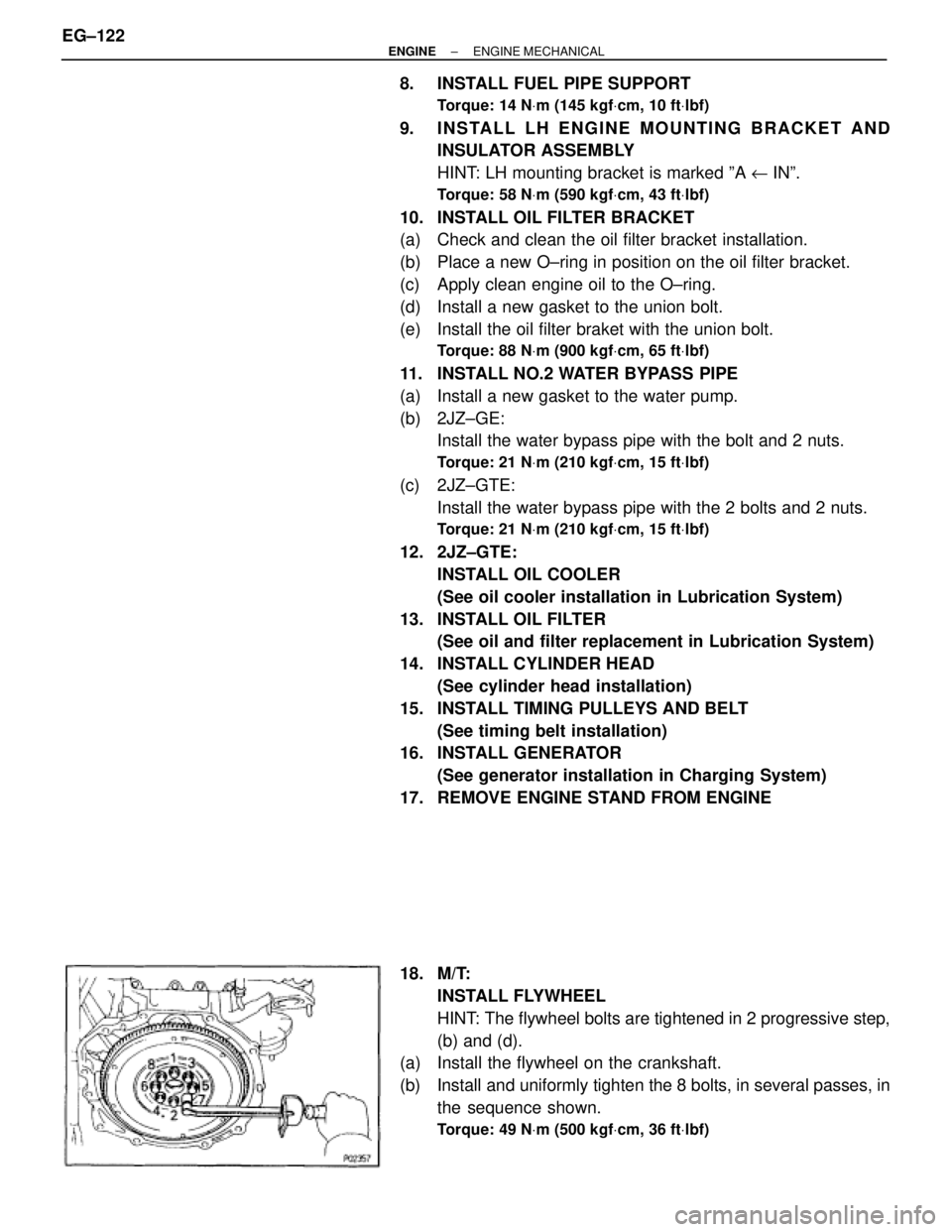
18. M/T:
INSTALL FLYWHEEL
HINT: The flywheel bolts are tightened in 2 progressive step,
(b) and (d).
(a) Install the flywheel on the crankshaft.
(b) Install and uniformly tighten the 8 bolts, in several passes, in
the sequence shown.
Torque: 49 NVm (500 kgfVcm, 36 ftVlbf)
EG±122± ENGINEENGINE MECHANICAL