Page 706 of 3115
ROOF PANEL (ASSY): Normal Roof
REMOVAL
BODY PANEL REPLACEMENTRE-68
Page 707 of 3115
INSTALLATION
Foamed Material
Application Area
Body Sealer
Swing Type Back
Door Only:
Roof Drip No. 2 Channel
1. Before temporarily installing the new parts,
apply body sealer to the windshield header
panel, roof panel reinforcement and back
door opening upper frame.
HINT:
1) Apply just enough sealer for the new parts to
make contact.
2) For other sealing points, refer to Section AR.
2. After installing the new parts, apply foamed
materials.
BODY PANEL REPLACEMENTRE-69
Page 708 of 3115
ROOF SIDE INNER REAR PANEL (ASSY)
REMOVAL (With the quarter panel rear extension
removed.)
BODY PANEL REPLACEMENTRE-40
Page 711 of 3115
1,472
(57.95)N-n O-o
1,613
(63.50)Vehicle Dimensions Left e Right
P-p
1,619
(63.74)Q-q
1,330
(52.36)R-r
1,442
(56.77)S-s
1,607
(63.27)N-r
or
n-R
1,649
(64.92)N-s
or
n-S
1,782
(70.16)1,734
(68.27)O-s
or
o-S
1,875
(73.82)P-q
or
p-QR-s
or
r-S
1,692
(66.61)
HINT: For symbols, capital letters indicate right side of vehicle,
small letters indicate left side of vehicle (Seen from rear).
(Three-Dimensional Distance)
mm (in.)
Hole dia.
Name
Roof side rail assembly mark
Quarter panel assembly mark
Quarter panel assembly mark Symbol
Q, q
R, r
S, s Hole dia.
Name
Center body pillar assembly mark
Center body pillar assembly mark
Rocker panel assembly mark Symbol
N, n
O, o
P, p
BODY OPENING AREAS
(Side View-Rear)
BODY DIMENSIONSDI-5
Page 714 of 3115

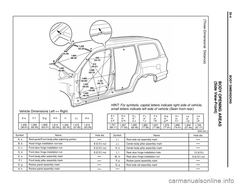
E-e
1,438
(56.61)1,599
(62.95)F-f
1,608
(63.31)G-gVehicle Dimensions Left e Right
1,614
(63.54)H-h
I-i
1,340
(52.76)1,472
(57.95)J-j K-k
1,610
(63.39)1,757
(69.17)E-f
or
e-F
1,827
(71.93)E-h
or
e-HE-j
or
e-J
1,585
(62.40)1,980
(77.95)F-j
or
f-J
1,821
(71.69)F-k
or
f-KG-p
or
g-P
1,979
(77.91)H-i
or
h-I
1,890
(74.41)I-q
or
i-Q
1,459
(57.44)1,706
(67.17)J-k
or
j-K
HINT: For symbols, capital letters indicate right side of vehicle,
small letters indicate left side of vehicle (Seen from rear).
(Three-Dimensional Distance)
mm (in.)
Hole dia.
13 (0.51)
8 (0.31) nut Name
Roof side rail assembly mark
Center body pillar assembly mark
Center body pillar assembly mark
Rear door hinge installation hole
Rear door hinge installation nut
Rocker panel assembly mark
Roof side rail assembly mark Symbol
I, i
J, j
K, k
L, l
M, m
P, p
Q, q Hole dia.
8 (0.31) nut
8 (0.31) nut
8 (0.31) nut Name
Roof panel/Front body pillar adjoining portion
Hood hinge installation nut-rear
Front door hinge installation nut
Front door hinge installation nut
Front body pillar assembly mark
Front body pillar assembly mark
Rocker panel assembly mark
Rocker panel assembly mark Symbol
A, a
B, b
C, c
D, d
E, e
F, f
G, g
H, h
BODY OPENING AREAS
(Side View-Front)
BODY DIMENSIONSDI-4
Page 740 of 3115

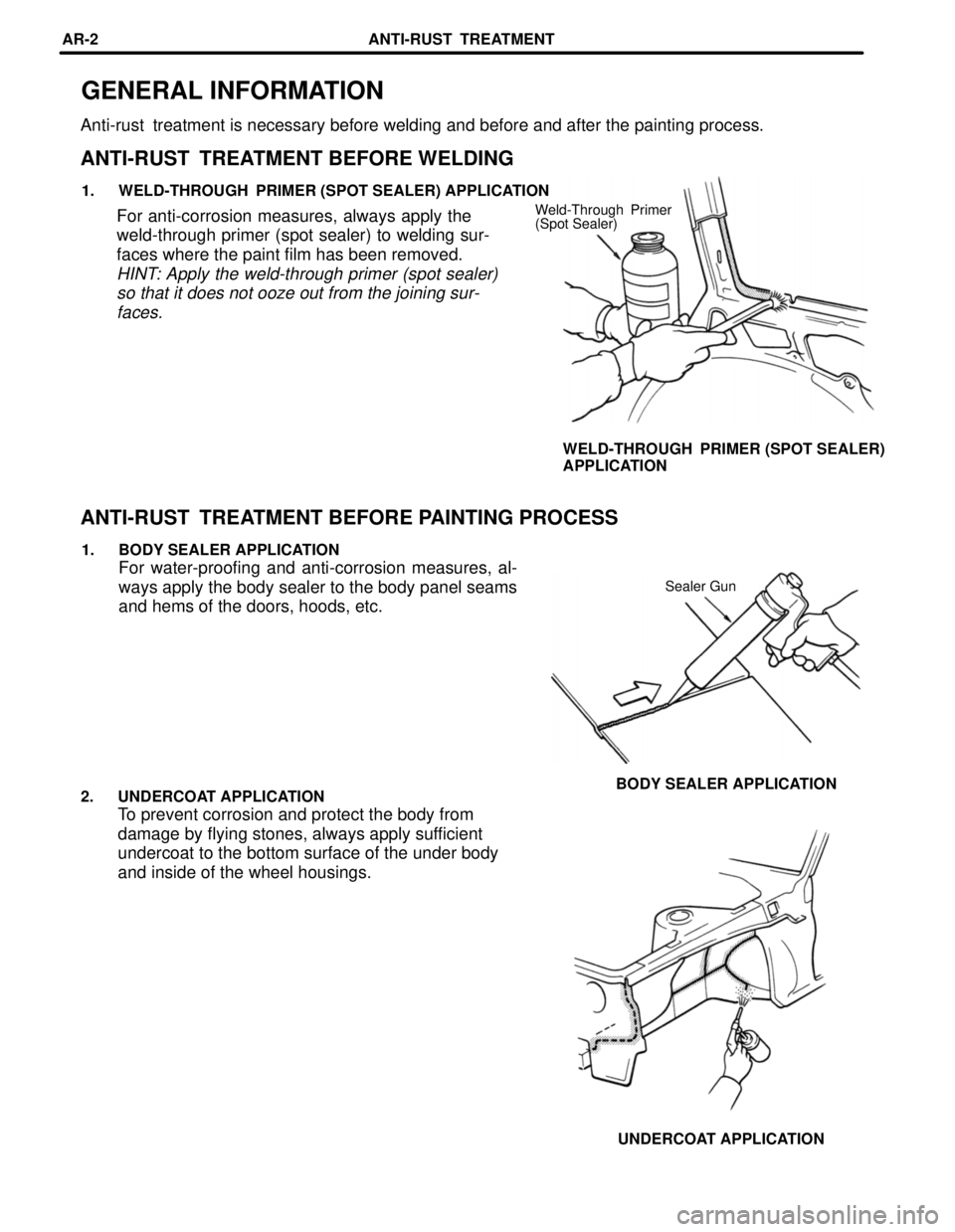
GENERAL INFORMATION
Anti-rust treatment is necessary before welding and before and after the painting process.
ANTI-RUST TREATMENT BEFORE WELDING
1. WELD-THROUGH PRIMER (SPOT SEALER) APPLICATION
Weld-Through Primer
(Spot Sealer)For anti-corrosion measures, always apply the
weld-through primer (spot sealer) to welding sur-
faces where the paint film has been removed.
HINT: Apply the weld-through primer (spot sealer)
so that it does not ooze out from the joining sur-
faces.
WELD-THROUGH PRIMER (SPOT SEALER)
APPLICATION
ANTI-RUST TREATMENT BEFORE PAINTING PROCESS
1. BODY SEALER APPLICATION
For water-proofing and anti-corrosion measures, al-
ways apply the body sealer to the body panel seams
and hems of the doors, hoods, etc.
Sealer Gun
BODY SEALER APPLICATION
2. UNDERCOAT APPLICATION
To prevent corrosion and protect the body from
damage by flying stones, always apply sufficient
undercoat to the bottom surface of the under body
and inside of the wheel housings.
UNDERCOAT APPLICATION ANTI-RUST TREATMENT
AR-2
Page 1918 of 3115

A 1
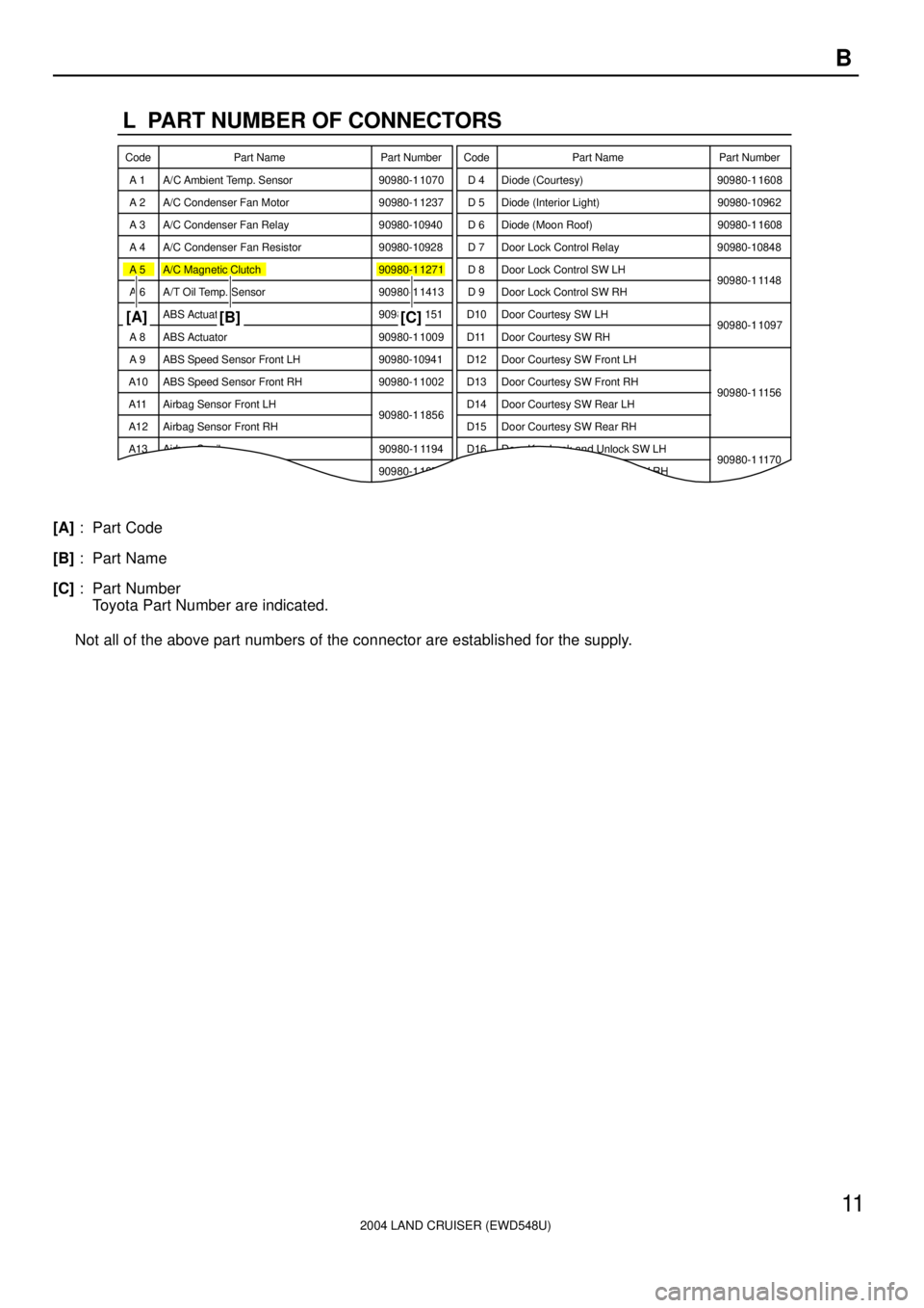
L PART NUMBER OF CONNECTORS
A/C Ambient Temp. Sensor Code
90980-1 1070Part Number
D 4 Diode (Courtesy) Code
90980-1 1608
A 2 A/C Condenser Fan Motor 90980-1 1237 D 5 Diode (Interior Light) 90980-10962
A 3 A/C Condenser Fan Relay 90980-10940 D 6 Diode (Moon Roof) 90980-1 1608
A 4 A/C Condenser Fan Resistor 90980-10928
90980-1 1271D 7 Door Lock Control Relay 90980-10848
A 5 A/C Magnetic Clutch
90980-1 1413D 8 Door Lock Control SW LH
90980-1 1148
A 6 A/T Oil Temp. Sensor
90980-1 1151D 9 Door Lock Control SW RH
A 7 ABS Actuator
90980-1 1009Door Courtesy SW LH
90980-1 1097
A 8 ABS Actuator
90980-10941Door Courtesy SW RH
A 9 ABS Speed Sensor Front LH
90980-1 1002Door Courtesy SW Front LH
ABS Speed Sensor Front RH
90980-1 1856Door Courtesy SW Front RH
90980-1 1156
Airbag Sensor Front LH Door Courtesy SW Rear LH
Airbag Sensor Front RH Door Courtesy SW Rear RH A10
A11
A12
A13 Airbag Squib 90980-1 1194 Door Key Lock and Unlock SW LH
90980-1 1170
90980-1 1070D10
D11
D12
D13
D14
D15
D16
D17 Door Key Lock and Unlock SW RHPart Number Part Name Part Name
[A]
[B] [C]
2004 LAND CRUISER (EWD548U)
11 B
[A]: Part Code
[B]: Part Name
[C]: Part Number
Toyota Part Number are indicated.
Not all of the above part numbers of the connector are established for the supply.
Page 1935 of 3115
2004 LAND CRUISER (EWD548U)
79 G
Connector Joining Wire Harness and Wire Harness
CodeJoining Wire Harness and Wire Harness (Connector Location)
IA2Engine Room No.2 Wire and Floor No.1 Wire (Left Kick Panel)
IB1Engine Room No.2 Wire and Dash Wire (Left Kick Panel)
IC2Front Door LH Wire and Dash Wire (Left Kick Panel)
ID3Dash Wire and Floor No 1 Wire (Left Kick Panel)ID4Dash Wire and Floor No.1 Wire (Left Kick Panel)
IE2Dash Wire and Roof No.1 Wire (Left Kick Panel)
IF1Instrument Panel Integration Wire and Instrument Panel Wire (Left Side of Instrument Panel)IF2Instrument Panel Integration Wire and Instrument Panel Wire (Left Side of Instrument Panel)
IG1
IG4Engine Room No.2 Wire and Dash Wire (Behind the Combination Meter)
IG5
g()