Page 1227 of 3115

A21025
Ignition Coil Connector
I1
I2
I3I4
I5I6
I7I8
Wire Harness Side:
A21023
E5
IGT8 IGT2
IGT4
IGT5 IGT6
IGT3 IGT7
IGT1
ECM Connector
DI-178
- DIAGNOSTICSENGINE
371 Author�: Date�:
2004 LAND CRUISER (RM1071U)
Check the harness and connector between the ignition coil
and the ECM (IGT terminal) connectors:
PREPARATION:
(a) Disconnect the I1, I2, I3, I4, I5, I6, I7 or I8 ignition coil con-
nector.
(b) Disconnect the E5 ECM connector.
CHECK:
Check the resistance between the wire harness side connec-
tors.
OK:
Tester ConnectionSpecified Condition
Ignition coil (I1-3) - IGT1 (E5-9)Below 1 W
Ignition coil (I2-3) - IGT2 (E5-8)Below 1 W
Ignition coil (I3-3) - IGT3 (E5-25)Below 1 W
Ignition coil (I4-3) - IGT4 (E5-11)Below 1 W
Ignition coil (I5-3) - IGT5 (E5-12)Below 1 W
Ignition coil (I6-3) - IGT6 (E5-26)Below 1 W
Ignition coil (I7-3) - IGT7 (E5-13)Below 1 W
Ignition coil (I8-3) - IGT8 (E5-10)Below 1 W
Ignition coil (I1-3) or IGT1 (E5-9) -
Body ground10 kW or higher
Ignition coil (I2-3) or IGT2 (E5-8) -
Body ground10 kW or higher
Ignition coil (I3-3) or IGT3 (E5-25) -
Body ground10 kW or higher
Ignition coil (I4-3) or IGT4 (E5-11) -
Body ground10 kW or higher
Ignition coil (I5-3) or IGT5 (E5-12) -
Body ground10 kW or higher
Ignition coil (I6-3) or IGT6 (E5-26) -
Body ground10 kW or higher
Ignition coil (I7-3) or IGT7 (E5-13) -
Body ground10 kW or higher
Ignition coil (I8-3) or IGT8 (E5-10) -
Body ground10 kW or higher
OK Replace ignition coil with igniter, then confirm
that there is no misfire.
NG
Repair or replace harness or connector.
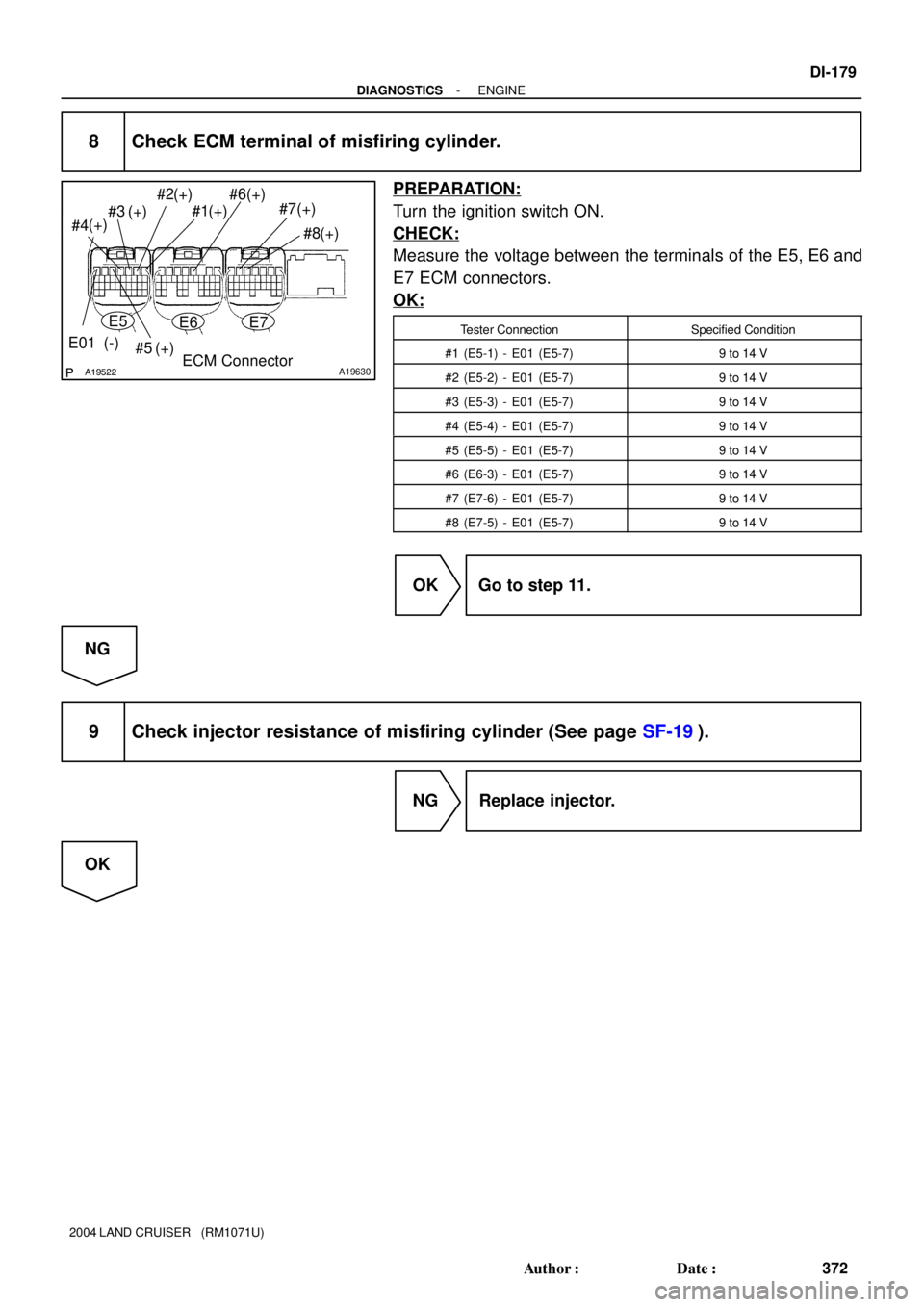
Page 1228 of 3115
A19522A19630
#8 #7 #6
#5 #3#2
#1
(+) (+)(+)
(+)(+)
(+)
(+)
#4(+)
E01 (-)
ECM Connector
E5E6E7
- DIAGNOSTICSENGINE
DI-179
372 Author�: Date�:
2004 LAND CRUISER (RM1071U)
8 Check ECM terminal of misfiring cylinder.
PREPARATION:
Turn the ignition switch ON.
CHECK:
Measure the voltage between the terminals of the E5, E6 and
E7 ECM connectors.
OK:
Tester ConnectionSpecified Condition
#1 (E5-1) - E01 (E5-7)9 to 14 V
#2 (E5-2) - E01 (E5-7)9 to 14 V
#3 (E5-3) - E01 (E5-7)9 to 14 V
#4 (E5-4) - E01 (E5-7)9 to 14 V
#5 (E5-5) - E01 (E5-7)9 to 14 V
#6 (E6-3) - E01 (E5-7)9 to 14 V
#7 (E7-6) - E01 (E5-7)9 to 14 V
#8 (E7-5) - E01 (E5-7)9 to 14 V
OK Go to step 11.
NG
9 Check injector resistance of misfiring cylinder (See page SF-19).
NG Replace injector.
OK
Page 1229 of 3115

A21343
I9I10
I11I12
I13I14
I15I16
Wire Harness Side:
Injector Connector
A21344ECM Connector E6
E7
#4
#5#2
#1
#3#6#7
#8
E5
A21345
I18
Wire Harness Side:
Ignition Switch Connector
IG2
DI-180
- DIAGNOSTICSENGINE
373 Author�: Date�:
2004 LAND CRUISER (RM1071U)
10 Check for open and short in harness and connector between ignition SW and in-
jector, injector and ECM of misfiring cylinder.
Check the harness and the connector between the injector
connector and the ECM connector:
PREPARATION:
(a) Disconnect the I9, I10, I11, I12, I13, I14, I15 or I16 injector
connector.
(b) Disconnect the E5, E6 or E7 ECM connector.
CHECK:
Measure the resistance between the wire harness side connec-
tors.
OK:
Tester ConnectionSpecified Condition
Injector (I9-2) - #1 (E5-1)Below 1 W
Injector (I10-2) - #2 (E5-2)Below 1 W
Injector (I11-2) - #3 (E5-3)Below 1 W
Injector (I12-2) - #4 (E5-4)Below 1 W
Injector (I13-2) - #5 (E5-5)Below 1 W
Injector (I14-2) - #6 (E6-3)Below 1 W
Injector (I15-2) - #7 (E7-6)Below 1 W
Injector (I16-2) - #8 (E7-5)Below 1 W
Injector (I9-2) or #1 (E5-1) -
Body ground10 kW or higher
Injector (I10-2) or #2 (E5-2) -
Body ground10 kW or higher
Injector (I11-2) or #3 (E5-3) -
Body ground10 kW or higher
Injector (I12-2) or #4 (E5-4) -
Body ground10 kW or higher
Injector (I13-2) or #5 (E5-5) -
Body ground10 kW or higher
Injector (I14-2) or #6 (E6-3) -
Body ground10 kW or higher
Injector (I15-2) or #7 (E7-6) -
Body ground10 kW or higher
Injector (I16-2) or #8 (E7-5) -
Body ground10 kW or higher
Page 1230 of 3115

Check the harness and connector between the injector
connector and the ignition switch:
PREPARATION:
(a) Disconnect the I9")
- DIAGNOSTICSENGINE
DI-181
374 Author�: Date�:
2004 LAND CRUISER (RM1071U)
Check the harness and connector between the injector
connector and the ignition switch:
PREPARATION:
(a) Disconnect the I9, I10, I11, I12, I13, I14, I15 or I16 injector
connector.
(b) Disconnect the I18 ignition switch connector.
CHECK:
Measure the resistance between the wire harness side connec-
tors.
OK:
Tester ConnectionSpecified Condition
Injector (I9-1) - IG2 (I18-6)Below 1 W
Injector (I10-1) - IG2 (I18-6)Below 1 W
Injector (I11-1) - IG2 (I18-6)Below 1 W
Injector (I12-1) - IG2 (I18-6)Below 1 W
Injector (I13-1) - IG2 (I18-6)Below 1 W
Injector (I14-1) - IG2 (I18-6)Below 1 W
Injector (I15-1) - IG2 (I18-6)Below 1 W
Injector (I16-1) - IG2 (I18-6)Below 1 W
Injector (I9-1) or IG2 (I18-6) -
Body ground10 kW or higher
Injector (I10-1) or IG2 (I18-6) -
Body ground10 kW or higher
Injector (I11-1) or IG2 (I18-6) -
Body ground10 kW or higher
Injector (I12-1) or IG2 (I18-6) -
Body ground10 kW or higher
Injector (I13-1) or IG2 (I18-6) -
Body ground10 kW or higher
Injector (I14-1) or IG2 (I18-6) -
Body ground10 kW or higher
Injector (I15-1) or IG2 (I18-6) -
Body ground10 kW or higher
Injector (I16-1) or IG2 (I18-6) -
Body ground10 kW or higher
NG Repair or replace harness or connector.
OK
Page 1233 of 3115
DI-184
- DIAGNOSTICSENGINE
377 Author�: Date�:
2004 LAND CRUISER (RM1071U)
17 Check intake air temperature and mass air flow rate.
PREPARATION:
(a) Connect the hand-held tester or the OBD II scan tool to the DLC3.
(b) Turn the ignition switch ON.
CHECK:
Check the intake air temperature.
(1) Select the item ºDIAGNOSIS/ENHANCED OBD II/DATA LIST/ALL/INTAKE AIRº.
(2) Read its value displayed on the hand-held tester or the OBD II scan tool.
OK:
Equivalent to ambient temperature
CHECK:
Check the air flow rate.
(1) Select the item ºDIAGNOSIS/ENHANCED OBD II/DATA LIST/ALL/MAFº.
(2) Read its value displayed on the hand-held tester or the OBD II scan tool.
OK:
ConditionAir Flow Rate (gm/s)
Ignition switch ON (do not start engine)0
Idling4 to 6
Running without load (2,500 rpm)13 to 20
Idling to quickly acceleratingAir flow rate fluctuates
NG Replace mass air flow meter.
OK
Page 1235 of 3115

DTC P0325 Knock Sensor")
A00068
KNK Signal Waveform
0.5 V
Division
0.5 V/
Division0 V
0 V5 msec./Division
0.2 msec./Division DI-186
- DIAGNOSTICSENGINE
379 Author�: Date�:
2004 LAND CRUISER (RM1071U)
DTC P0325 Knock Sensor 1 Circuit (Bank 1 or Single
Sensor)
DTC P0330 Knock Sensor 2 Circuit (Bank 2)
CIRCUIT DESCRIPTION
Each knock sensor is fitted to the right bank and left bank of the cylinder block to detect engine knocking.
This sensor contains a piezoelectric element which generates a voltage when it becomes deformed. The
piezoelectric element sends a signal to the ECM, when the cylinder block vibrates due to knocking. If engine
knocking occurs, ignition timing is retarded to suppress it.
DTC No.DTC Detecting ConditionTrouble Area
P0325No signal of knock sensor 1 signal to ECM with engine speed
between 2,000 rpm and 5,400 rpm�Open or short in knock sensor 1 circuit
�Knock sensor 1 (looseness)
�ECM
P0330No signal of knock sensor 2 signal to ECM with engine speed
between 2,000 rpm and 5,400 rpm�Open or short in knock sensor 2 circuit
�Knock sensor 2 (looseness)
�ECM
HINT:
�Bank 1 refers to the bank that includes cylinder No. 1.
�Bank 2 refers the the bank that does not include cylinder No. 1.
Reference: INSPECTION USING OSCILLOSCOPE
�With the engine racing (4,000 rpm), check the waveform
between terminals KNK1 and KNK2 of the ECM connec-
tor and body ground.
HINT:
The correct waveform is as shown.
�Spread the time on the horizontal axis, and confirm that
period of the wave is 0.13 msec. (Normal mode vibration
frequency of knock sensor: 8.1 kHz)
HINT:
If normal mode vibration frequency is not 8.1 kHz, the sensor
has malfunction.
DI1LQ-14
Page 1236 of 3115

MONITOR DESCRIPTION
The knock sensor located on the cylinder block, detects spark knock.
When spark knock occurs, the senso")
- DIAGNOSTICSENGINE
DI-187
380 Author�: Date�:
2004 LAND CRUISER (RM1071U)
MONITOR DESCRIPTION
The knock sensor located on the cylinder block, detects spark knock.
When spark knock occurs, the sensor pick-up vibrates in a specific frequency range. When the ECM detects
the voltage in this frequency range, it retards the ignition timing to suppress the spark knock.
The ECM also senses background engine noise with the knock sensor and uses this noise to check for faults
in the sensor. If the knock sensor signal level is too low for more than 10 sec., and if the knock sensor output
voltage is out of normal range, the ECM interprets this as a fault in the knock sensor and sets a DTC.
MONITOR STRATEGY
RltdDTCP0325Knock sensor (Bank 1) range check or rationalityRelated DTCsP0330Knock sensor (Bank 2) range check or rationality
Main sensors/componentsKnock sensor
Required sensors/componentsRelated sensors/components
Crankshaft position sensor, Camshaft position
sensor, Engine coolant temperature sensor,
Mass air flow meter
Frequency of operationContinuous
Duration10 sec.
MIL operationImmediate
Sequence of operationNone
TYPICAL ENABLING CONDITIONS
ItSpecificationItemMinimumMaximum
The monitor will run whenever the follow-
ing DTCs are not presentSee ºList of disable a monitorº (on page DI-3)
Battery voltage10 V-
IdleOFF
Time after engine start5 sec.-
Engine coolant temperature60�C (140�F)-
Intake air amount per revolution0.45 g/rev-
Engine speed2,000 rpm5,400 rpm
TYPICAL MALFUNCTION THRESHOLDS
Detection CriteriaThreshold
Sensor failure is indicated when the knock sensor output
level is below the specific threshold for:10 sec.
Page 1238 of 3115

FI7050A01996A01997A19886
ECM
KNK1
KNK2 22
33
Female
Connector Male
Connector1
1EC1
E6
2 1
3 21
321
E6
EC1
Knock Sensor 1
Knock Sensor 2
- DIAGNOSTICSENGINE
DI-189
382 Author�: Date�:
2004 LAND CRUISER (RM1071U)
INSPECTION PROCEDURE
HINT:
�DTC P0325 is for the bank 1 knock sensor circuit.
�DTC P0330 is for the bank 2 knock sensor circuit.
�Read freeze frame data using the hand-held tester or the OBD II scan tool. Freeze frame data records
the engine conditions when a malfunction is detected. When troubleshooting, freeze frame data can
help determine if the vehicle was running or stopped, if the engine was warmed up or not, if the air-fuel
ratio was lean or rich, as well as other data from the time when a malfunction occurred.
1 Connect OBD II scan tool or hand-held tester, and check knock sensor circuit.
PREPARATION:
(a) Connect the OBD II scan tool or hand-held tester to the
DLC3.
(b) Disconnect the EC1 connector.
(c) Connect the terminals of the disconnected EC1 male con-
nector and EC1 female as follows.
Male connector eFemale connector
Terminal 2 e Terminal 3
Terminal 3 e Terminal 2
(d) Turn ignition switch ON and push the OBD II scan tool or
hand-held tester main switch ON.
(e) After the engine is warmed up, perform quick racing to
4,000 rpm 3 times.
CHECK:
Check the DTC.
RESULT:
Type IDTC same as when vehicle brought in
P0325 " P0325 or P0330 " P0330
Type IIDTC different to when vehicle brought in
P0325 " P0330 or P0330 " P0325
Type II Go to step 3.
Type I