Page 1261 of 3115
A19522A19630
IGT2
IGT3 IGT4
IGT6IGT8
IGT1
IGT7 IGT5(+) (+) (+)
(+) (+)
(+)
(+) (+)
ECM Connector
E7E1 (-)E5
DI-212
- DIAGNOSTICSENGINE
405 Author�: Date�:
2004 LAND CRUISER (RM1071U)
6 Disconnect ignition coil with igniter connector, and check voltage between ter-
minals IGT1 - IGT8 of ECM connector and body ground.
PREPARATION:
Disconnect the I1, I2, I3, I4, I5, I6, I7 or I8 ignition coil with igniter
connector.
CHECK:
Measure the voltage between terminals the E5 and E7 ECM
connectors when the engine is cranked.
OK:
Tester ConnectionSpecified Condition
IGT1 (E5-9) - E1 (E7-1)
IGT2 (E5-8) - E1 (E7-1)
IGT3 (E5-25) - E1 (E7-1)
IGT4 (E5-11) - E1 (E7-1)45VIGT5 (E5-12) - E1 (E7-1)4.5 V or more
IGT6 (E5-26) - E1 (E7-1)
IGT7 (E5-13) - E1 (E7-1)
IGT8 (E5-10) - E1 (E7-1)
NG Replace ECM (See page SF-60).
OK
Page 1262 of 3115
A21025
Wire Harness Side:
I1
I2
I3I4
I5I6
I7I8Ignition Coil with
Igniter Connector
- DIAGNOSTICSENGINE
DI-213
406 Author�: Date�:
2004 LAND CRUISER (RM1071U)
7 Check ignition coil with igniter power source circuit.
PREPARATION:
Disconnect the I1, I2, I3, I4, I5, I6, I7 or I8 ignition coil with igniter
connector.
CHECK:
Measure the voltage between the terminal of the wire harness
side connector and body ground.
OK:
Tester ConnectionSpecified Condition
I1-1 - Body ground
I2-1 - Body ground
I3-1 - Body ground
I4-1 - Body ground9t 14VI5-1 - Body ground9 to 14 V
I6-1 - Body ground
I7-1 - Body ground
I8-1 - Body ground
OK Repair ignition coil with igniter.
NG
Page 1263 of 3115

A21025
Wire Harness Side:
I1
I2
I3I4
I5I6
I7I8Ignition Coil with Igniter
1 234
5 678
A21030
Wire Harness Side:
I18
Ignition SwitchIG2
DI-214
- DIAGNOSTICSENGINE
407 Author�: Date�:
2004 LAND CRUISER (RM1071U)
8 Check for open and short in harness and connector between ignition switch and
ignition coil with igniter.
PREPARATION:
(a) Disconnect the I1, 2, I3, I4, I5, I6, I7 or I8 ignition coil with
igniter connector.
(b) Disconnect the I18 ignition switch connector.
CHECK:
Measure the resistance between the wire harness side connec-
tors.
OK:
Tester ConnectionSpecified Condition
Ignition coil (I1-1) - IG2 (I18-6)Below 1 W
Ignition coil (I2-1) - IG2 (I18-6)Below 1 W
Ignition coil (I3-1) - IG2 (I18-6)Below 1 W
Ignition coil (I4-1) - IG2 (I18-6)Below 1 W
Ignition coil (I5-1) - IG2 (I18-6)Below 1 W
Ignition coil (I6-1) - IG2 (I18-6)Below 1 W
Ignition coil (I7-1) - IG2 (I18-6)Below 1 W
Ignition coil (I8-1) - IG2 (I18-6)Below 1 W
Ignition coil (I1-1) or IG2 (I18-6) -
Body ground10 kW or higher
Ignition coil (I2-1) or IG2 (I18-6) -
Body ground10 kW or higher
Ignition coil (I3-1) or IG2 (I18-6) -
Body ground10 kW or higher
Ignition coil (I4-1) or IG2 (I18-6) -
Body ground10 kW or higher
Ignition coil (I5-1) or IG2 (I18-6) -
Body ground10 kW or higher
Ignition coil (I6-1) or IG2 (I18-6) -
Body ground10 kW or higher
Ignition coil (I7-1) or IG2 (I18-6) -
Body ground10 kW or higher
Ignition coil (I8-1) or IG2 (I18-6) -
Body ground10 kW or higher
NG Repair or replace harness or connector.
OK
Replace ignition coil with igniter.
Page 1268 of 3115

- DIAGNOSTICSENGINE
DI-219
412 Author�: Date�:
INSPECTION PROCEDURE
HINT:
Read freeze frame data using the hand-held tester or the OBD II scan tool. Freeze frame data records the
engine conditions when a malfunction is detected. When troubleshooting, freeze frame data can help deter-
mine if the vehicle was running or stopped, if the engine was warmed up or not, if the air-fuel ratio was lean
or rich, as well as other data from the time when a malfunction occurred.
1 Are there any other codes (besides DTC P0420 or P0430) being output?
PREPARATION:
(a) Connect the hand-held tester or the OBD II scan tool to the DLC3.
(b) Turn the ignition switch ON and push the hand-held tester or OBD II scan tool main switch ON.
(c) When using hand-held tester, enter the following menus: DIAGNOSIS / ENHANCED OBD II / DTC
INFO / CURRENT CODES.
CHECK:
Read the DTC using the hand-held tester or the OBD II scan tool.
RESULT:
Display (DTC Output)Proceed to
ºP0420 and/or P0430ºA
ºP0420 or P0430º and other DTCsB
HINT:
If any other codes besides ºP0420 and/or P0430º are output, perform the troubleshooting for those DTCs
first.
B Go to relevant DTC chart (See page DI-36).
A
2 Check gas leakage on exhaust system.
NG Repair or replace exhaust gas leakage point.
OK
3 Check heated oxygen sensor (bank 1, 2 sensor 1) (See page SF-57).
HINT:
Refer to the hint following the end of this flowchart.
NG Replace heated oxygen sensor.
OK
Page 1269 of 3115
 (See page SF-57).
HINT:
Refer to the hint following the end of this flowchart.
NG Replace heated oxygen")
DI-220
- DIAGNOSTICSENGINE
413 Author�: Date�:
4 Check heated oxygen sensor (bank 1, 2 sensor 2) (See page SF-57).
HINT:
Refer to the hint following the end of this flowchart.
NG Replace heated oxygen sensor.
OK
Replace the front and rear three-way catalyt-
ic converter in the bank a malfunction is de-
tected.
HINT:
Hand-held tester only:
The narrowing down the trouble area is possible by performing ACTIVE TEST of the following ºA/F CON-
TROLº (Heated oxygen sensor or another can be distinguished).
(a) Perform ACTIVE TEST by hand-held tester (A/F CONTROL).
HINT:
ºA/F CONTROLº is the ACTIVE TEST which changes the injection volume to -12.5 % or +25 %.
(1) Connect the hand-held tester to the DLC3 on the vehicle.
(2) Turn the ignition switch ON.
(3) Warm up the engine with the engine speed at 2,500 rpm for approximately 90 seconds.
(4) Select the item ºDIAGNOSIS / ENHANCED OBD II / ACTIVE TEST / A/F CONTROLº.
(5) Perform ºA/F CONTROLº with the engine in an idle condition (press the right or left button).
RESULT:
Heated oxygen sensor reacts in accordance with increase and decrease of injection volume
+25 % " rich output: More than 0.5 V
-12.5 % " lean output: Less than 0.4 V
Page 1280 of 3115
 Disconnect the vacuum hose for the CCV VSV from the
charcoa")
A10150A10149BE6653
A10281VSV is OFFVSV is ON ON
Air
FAir
E
F E
- DIAGNOSTICSENGINE
DI-231
424 Author�: Date�:
9 Check CCV.
PREPARATION:
(a) Disconnect the vacuum hose for the CCV VSV from the
charcoal canister.
(b) Turn the ignition switch ON and push the hand-held tes-
ter main switch ON.
(c) Select the ºENHANCED OBD II / ACTIVE TESTº mode on
the hand-held tester.
(d) Select the item ºCAN CTRL VSV / ALLº in the ACTIVE
TEST and operate CCV.
CHECK:
Check the VSV operation when it is operated by the hand-held
tester.
OK:
VSV is ON:
Air does not flow from port E to port F.
VSV is OFF:
Air from port E flows out through port F.
OK Go to step 13.
NG
10 Check vacuum hose between CCV and charcoal canister.
CHECK:
(a) Check that the vacuum hose is connected correctly.
(b) Check the vacuum hose for looseness and disconnection.
(c) Check the vacuum hose for cracks, hole damage, and blockage.
NG Repair or replace vacuum hose.
OK
11 Check operation of CCV (See page SF-48).
NG Replace CCV.
OK
Page 1281 of 3115
BE6653A10143A10144A10801VSV is ONVSV is OFF ON
Air
Air
E
FE
F
DI-232
- DIAGNOSTICSENGINE
425 Author�: Date�:
12 Check for open and short in harness and connector between EFI or ECD relay
and CCV, and CCV and ECM (See page IN-36).
NG Repair or replace harness or connector.
OK
Replace ECM (See page SF-60).
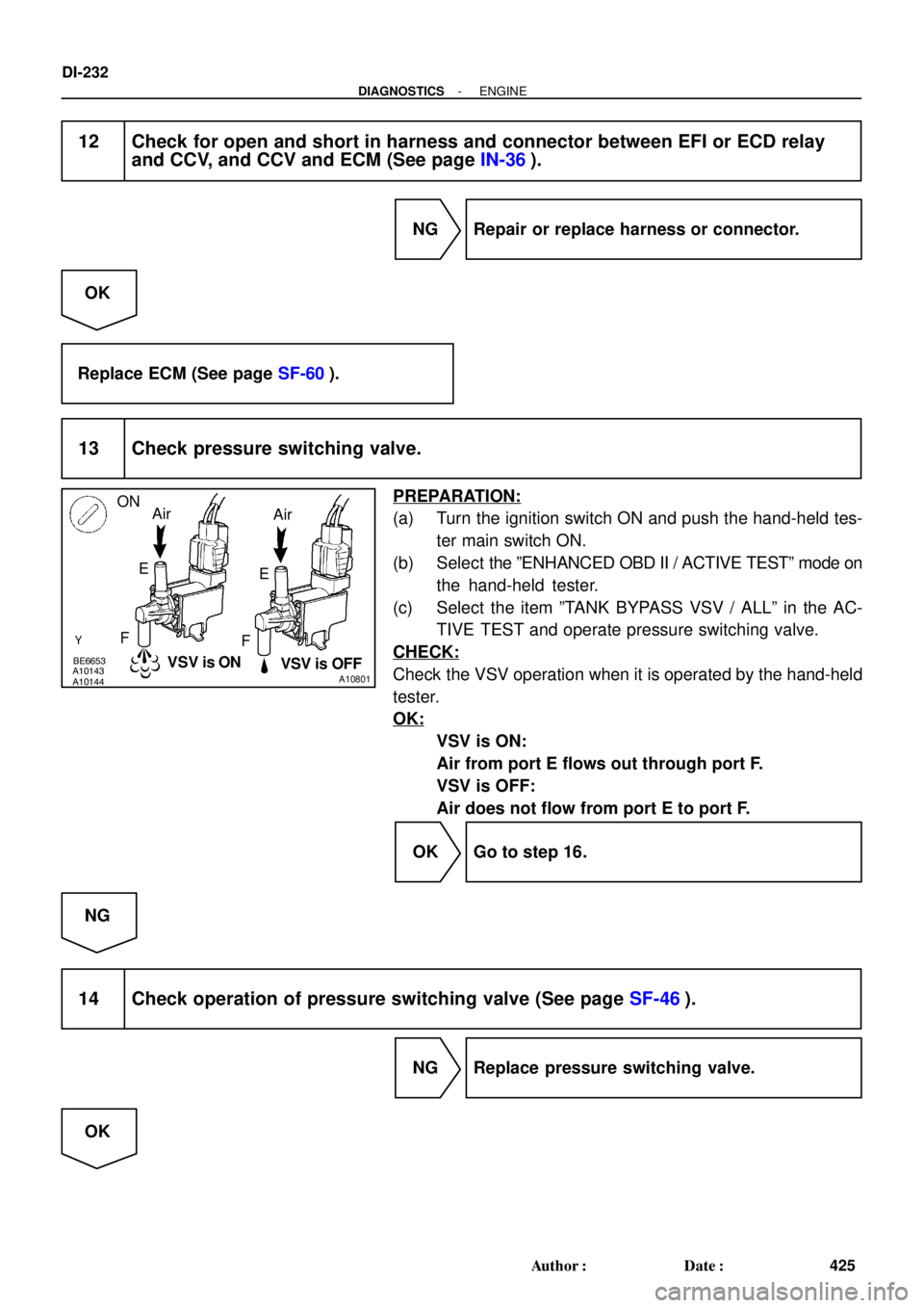
13 Check pressure switching valve.
PREPARATION:
(a) Turn the ignition switch ON and push the hand-held tes-
ter main switch ON.
(b) Select the ºENHANCED OBD II / ACTIVE TESTº mode on
the hand-held tester.
(c) Select the item ºTANK BYPASS VSV / ALLº in the AC-
TIVE TEST and operate pressure switching valve.
CHECK:
Check the VSV operation when it is operated by the hand-held
tester.
OK:
VSV is ON:
Air from port E flows out through port F.
VSV is OFF:
Air does not flow from port E to port F.
OK Go to step 16.
NG
14 Check operation of pressure switching valve (See page SF-46).
NG Replace pressure switching valve.
OK
Page 1283 of 3115
A19522A19630
VC
E2(+)
(-) E5
ECM Connector
DI-234
- DIAGNOSTICSENGINE
427 Author�: Date�:
18 Check hose and tube between fuel tank and charcoal canister.
CHECK:
(a) Check for proper connection of the fuel tank and fuel evap pipe (See page EC-2), fuel evap pipe and
fuel tube under the floor, fuel tube under the floor and charcoal canister.
(b) Check the hose and tube for cracks, hole and damage.
NG Repair or replace hose and tube.
OK
19 Check voltage between terminals VC and E2 of ECM connector.
CHECK:
Turn the ignition switch ON.
CHECK:
Measure the voltage between terminals the E5 ECM connector.
OK:
Tester ConnectionSpecified Condition
VC (E5-18) - E2 (E5-28)4.5 to 5.5 V
NG Replace ECM (See page SF-60).
OK