Page 204 of 3115

27 Noise NOISE PRODUCED BY VIBRATION OR SHOCK WHILE DRIVING
No
Ye s Is radio assembly properly installed?
Noise is produced from static eletricity accumulating in the vehicle body. With vehicles stationary lightly tap each system.
Is noise produced?Install properly.
Each system faulty. Is speaker properly installed?
No
No Ye s
Ye s
28 Noise NOISE PRODUCED WHEN ENGINE STARTS
NoYe s Whistling noise which becomes high-pitched when
accelerator strongly depressed, disappears shortly
after engine stops.Generator noise.
A/C noise.
Fuel gauge noise.
Horn noise.
Ignition noise.
Turn signal noise.
Washer noise.
Engine coolant temp. gauge noise.
Wiper noise. Whining noise occurs when A/C is operating.
Scratching noise occurs during sudden acceleration, driving on rough
roads or when ignition switch is turned ON.
Clicking sound is heard when horn button is pressed, then
released. Whirring/grating sound is heard when pushed
continuously.
Murmuring sound stops when engine stops.
Tick-tack noise occurs in co-ordination with blinking
offlasher.
Noise occurs during window washer operation.
Scratching noise occurs while engine is running,
and continues a while even after engine stops.
Scraping noise in line with wiper beat.
Other type of noiseYe s
Ye s
Ye s
Ye s
Ye s
Ye s
Ye s
Ye s No
No
No
No
No
No
No
No
BE-168
- BODY ELECTRICALAUDIO SYSTEM
2541 Author�: Date�:
2004 LAND CRUISER (RM1071U)
Page 251 of 3115
BE0H9-08
I25531
Switch BodyWiper and Washer Switch
Light Control Switch and
Headlight Dimmer Switch
Spiral Cable
Tilt and Telescopic Switch
- BODY ELECTRICALHEADLIGHT AND TAILLIGHT SYSTEM
BE-31
2404 Author�: Date�:
2004 LAND CRUISER (RM1071U)
COMPONENTS
Page 297 of 3115

BE-24
- BODY ELECTRICALPOWER SOURCE
2397 Author�: Date�:
2004 LAND CRUISER (RM1071U) ACC 13 - Ground
Ignition switch ACCBattery positive voltage
CIG 15 - GroundIgnition switch ACCBattery positive voltage
PWR OUTLET 17 - GroundIgnition switch ACCBattery positive voltage
OBD-2 20 - GroundConstantBattery positive voltage
STOP 22 - GroundConstantBattery positive voltage
A/C 24 - GroundIgnition switch ONBattery positive voltage
BATT CHARGE 26 - GroundConstantBattery positive voltage
DBL LOCK 39 - GroundConstantBattery positive voltage
ECU-B1 29 - GroundConstantBattery positive voltage
ECU-IG1 32 - GroundIgnition switch ONBattery positive voltage
GAUGE1 34 - GroundIgnition switch ONBattery positive voltage
EFI or ECD NO.2 35 - GroundConstantBattery positive voltage
RR WIPER 37 - GroundIgnition switch ONBattery positive voltage
SUN ROOF 39 - GroundConstantBattery positive voltage
DOOR 41 - GroundConstantBattery positive voltage
LH SEAT 43 - GroundConstantBattery positive voltage
IDLE UP 46 - GroundRear deffoger system ONBattery positive voltage
If the circuit is not as specified, inspect the circuits connected
to other parts.
(b) Remove the relay from the junction block and inspect the
connector on junction block side.
Relay Tester connectionConditionSpecified condition
DOME 1 - GroundConstantBattery positive voltage
DOME 5 - GroundConstantBattery positive voltage
ACC 5 - GroundConstantBattery positive voltage
ACC 2 - GroundIgnition switch ONBattery positive voltage
IG1 NO.2 5 - GroundConstantBattery positive voltage
IG1 NO.2 2 - GroundIgnition switch ONBattery positive voltage
DEFOG 5 - GroundConstantBattery positive voltage
DEFOG 1 - GroundIgnition switch ONBattery positive voltage
If the circuit is not as specified, inspect the circuits connected
to other parts.
Page 300 of 3115

- BODY ELECTRICALPOWER SOURCE
BE-27
2400 Author�: Date�:
2004 LAND CRUISER (RM1071U) DIFF 12 - Ground
Ignition switch ONBattery positive voltage
ECU-B2 13 - GroundConstantBattery positive voltage
P/W (FR) 15 - GroundConstantBattery positive voltage
P/W (RR) 17 - GroundConstantBattery positive voltage
SECURITY 20 - GroundConstantBattery positive voltage
IGN 21 - GroundIgnition switch ONBattery positive voltage
MET 23 - GroundIgnition switch ONBattery positive voltage
GAUGE2 25 - GroundIgnition switch ONBattery positive voltage
SEAT HTR 27 - GroundIgnition switch ONBattery positive voltage
ECU-IG2 29 - GroundIgnition switch ONBattery positive voltage
WIPER 31 - GroundIgnition switch ONBattery positive voltage
RH SEAT 33 - GroundConstantBattery positive voltage
RR A/C 35 - GroundConstantBattery positive voltage
TIL & TEL 37 - GroundConstantBattery positive voltage
If the circuit is not as specified, inspect the circuits connected
to other parts.
Remove the relay from the junction block and inspect the con-
nector on junction block side.
Relay Tester connectionConditionSpecified condition
ACC CUT 2 - GroundConstantBattery positive voltage
ACC CUT 4 - GroundIgnition Switch ACCBattery positive voltage
IG1 NO.3 5 - GroundConstantBattery positive voltage
IG1 NO.3 2 - GroundIgnition Switch ONBattery positive voltage
If the circuit is not as specified, inspect the circuits connected
to other parts.
Page 303 of 3115
I24922
Cowl Side J/B LH
ABCD
Relays:
A. DEFOG
B. IG1 No.2
C. ACC
D. DOME Fuses:
1. AHC-IG
2. POWER HTR
3. FUEL HTR
4. AHC-B
5. DEFOG
6. AM1
7. ACC
8. CIG
9. PWR OUTLET
10. OBD-2
11. STOP
12. A/C
13. BATT CHARGE
14. DBL LOCK
15. ECU-B1
16. ECU-IG1
17. GAUGE1
18. EFI or ECD NO.2
19. RR WIPER
20. SUN ROOF
21. DOOR
22. LH SEAT
23. IDLE UP
1 2 3 4 5 6 7 8 9
10 11 12 13 14 15 16 17 18
19 20 21 22 23
- BODY ELECTRICALPOWER SOURCE
BE-13
2386 Author�: Date�:
2004 LAND CRUISER (RM1071U)
Page 304 of 3115
I24923
Cowl Side J/B RH
Relays:
A. ACC CUT
B. IG1 NO.3
C. POWER MAIN Fuses:
1. P/W (RL)
2. P/W (FL)
3. VGRS
4. DOME
5. RADIO
6. WASHER
7. DIFF
8. ECU-B2
9. P/W(FR)
10.P/W(RR)
11. SECURITY
12. IGN
13. MET
14. GAUGE 2
15. SEAT HTR
16. ECU-IG2
17. WIPER
18. RH SEAT
19. RR A/C
20. TIL&TEL
1 2 3 4 5 6 7 8
9 10 11 12 13 14 15 16 17
18 19 20 21 22
BA
BE-14
- BODY ELECTRICALPOWER SOURCE
2387 Author�: Date�:
2004 LAND CRUISER (RM1071U)
Page 338 of 3115

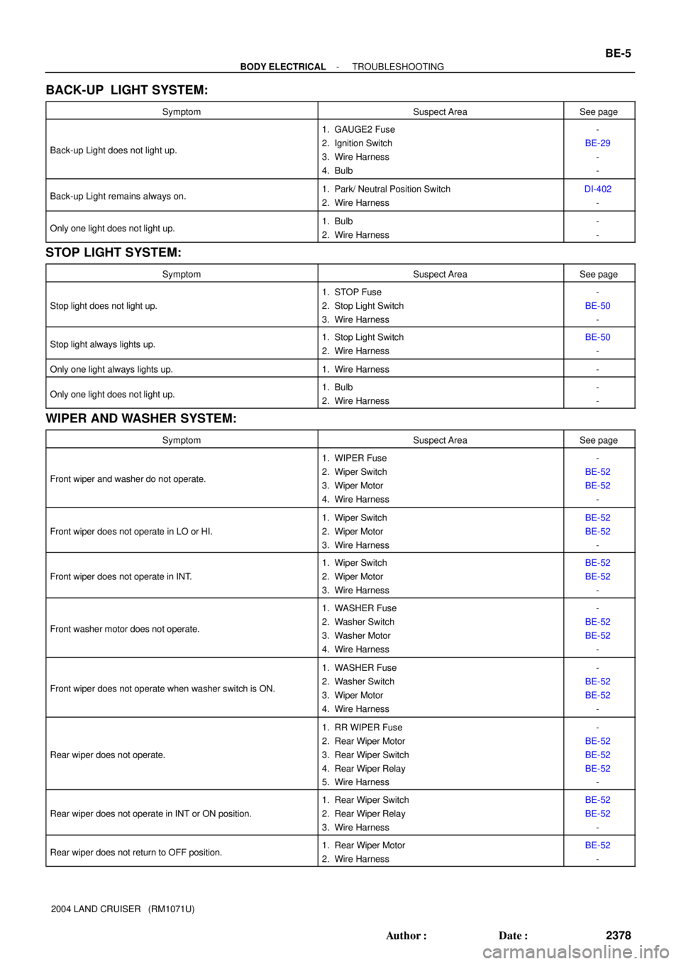
- BODY ELECTRICALTROUBLESHOOTING
BE-5
2378 Author�: Date�:
2004 LAND CRUISER (RM1071U)
BACK-UP LIGHT SYSTEM:
SymptomSuspect AreaSee page
Back-up Light does not light up.
1. GAUGE2 Fuse
2. Ignition Switch
3. Wire Harness
4. Bulb-
BE-29
-
-
Back-up Light remains always on.1. Park/ Neutral Position Switch
2. Wire HarnessDI-402
-
Only one light does not light up.1. Bulb
2. Wire Harness-
-
STOP LIGHT SYSTEM:
SymptomSuspect AreaSee page
Stop light does not light up.
1. STOP Fuse
2. Stop Light Switch
3. Wire Harness-
BE-50
-
Stop light always lights up.1. Stop Light Switch
2. Wire HarnessBE-50
-
Only one light always lights up.1. Wire Harness-
Only one light does not light up.1. Bulb
2. Wire Harness-
-
WIPER AND WASHER SYSTEM:
SymptomSuspect AreaSee page
Front wiper and washer do not operate.
1. WIPER Fuse
2. Wiper Switch
3. Wiper Motor
4. Wire Harness-
BE-52
BE-52
-
Front wiper does not operate in LO or HI.
1. Wiper Switch
2. Wiper Motor
3. Wire HarnessBE-52
BE-52
-
Front wiper does not operate in INT.
1. Wiper Switch
2. Wiper Motor
3. Wire HarnessBE-52
BE-52
-
Front washer motor does not operate.
1. WASHER Fuse
2. Washer Switch
3. Washer Motor
4. Wire Harness-
BE-52
BE-52
-
Front wiper does not operate when washer switch is ON.
1. WASHER Fuse
2. Washer Switch
3. Wiper Motor
4. Wire Harness-
BE-52
BE-52
-
Rear wiper does not operate.
1. RR WIPER Fuse
2. Rear Wiper Motor
3. Rear Wiper Switch
4. Rear Wiper Relay
5. Wire Harness-
BE-52
BE-52
BE-52
-
Rear wiper does not operate in INT or ON position.
1. Rear Wiper Switch
2. Rear Wiper Relay
3. Wire HarnessBE-52
BE-52
-
Rear wiper does not return to OFF position.1. Rear Wiper Motor
2. Wire HarnessBE-52
-
Page 339 of 3115

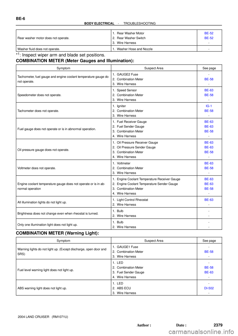
BE-6
- BODY ELECTRICALTROUBLESHOOTING
2379 Author�: Date�:
2004 LAND CRUISER (RM1071U) Rear washer motor does not operate.
1. Rear Washer Motor
2. Rear Washer Switch
3. Wire HarnessBE-52
BE-52
-
Washer fluid does not operate.1. Washer Hose and Nozzle-
*1: Inspect wiper arm and blade set positions.
COMBINATION METER (Meter Gauges and Illumination):
SymptomSuspect AreaSee page
Tachometer, fuel gauge and engine coolant temperature gauge do
not operate.1. GAUGE2 Fuse
2. Combination Meter
3. Wire Harness-
BE-58
-
Speedometer does not operate.
1. Speed Sensor
2. Combination Meter
3. Wire HarnessBE-63
BE-58
-
Tachometer does not operate.
1. Igniter
2. Combination Meter
3. Wire HarnessIG-1
BE-58
-
Fuel gauge does not operate or is in abnormal operation.
1. Fuel Receiver Gauge
2. Fuel Sender Gauge
3. Combination Meter
4. Wire HarnessBE-63
BE-63
BE-58
-
Oil pressure gauge does not operate.
1. Oil Pressure Receiver Gauge
2. Oil Pressure Sender Gauge
3. Combination Meter
4. Wire HarnessBE-63
BE-63
BE-58
-
Voltmeter does not operate.
1. Voltmeter
2. Combination Meter
3. Wire HarnessBE-63
BE-58
-
Engine coolant temperature gauge does not operate or is in ab-
normal operation
1. Engine Coolant Temperature Receiver Gauge
2. Engine Coolant Temperature Sender Gauge
3. Combination Meter
4. Wire HarnessBE-63
BE-63
BE-58
-
All illumination lights do not light up.1. Light Control Rheostat
2. Wire HarnessBE-63
-
Brightness does not change even when rheostat is turned.1. Bulb
2. Wire Harness-
-
Only one illumination light does not light up.1. Bulb
2. Wire Harness-
-
COMBINATION METER (Warning Light):
SymptomSuspect AreaSee page
Warning lights do not light up. (Except discharge, open door and
SRS)1. GAUGE1 Fuse
2. Combination Meter
3. Wire Harness-
BE-58
-
Fuel level warning light does not light up.
1. LED
2. Combination Meter
3. Fuel Sender Gauge
4. Wire Harness-
BE-58
BE-63
-
ABS warning light does not light up.
1. LED
2. ABS ECU
3. Wire Harness-
DI-502
-