Page 67 of 3115

REMOVAL
1. DISCHARGE")
AC1K6-04
I07892
I03838
SST
I03839
SST
SST Push Pull
Release
Lever
I06878
CorrectWrong AC-24
- AIR CONDITIONINGFRONT COOLING UNIT
2749 Author�: Date�:
2004 LAND CRUISER (RM1071U)
REMOVAL
1. DISCHARGE REFRIGERANT FROM REFRIGERATION
SYSTEM
HINT:
At the time of installation, first evacuate air from refrigeration
system.
Then, charge the system with the refrigerant and inspect for
leaks of the refrigerant.
Specified amount: 1,050 ± 50 g (37.03 ± 1.76 oz.)
2. DISCONNECT LIQUID AND SUCTION TUBES
(a) Using SST, remove the 2 piping clamps.
SST 09870-00025 (Liquid tube)
09870-00015 (Suction tube)
(1) Insert SST to piping clamp.
HINT:
Confirm the direction of the piping clamp claw and SST referring
to the illustration on the caution label.
(2) Push down SST and release the clamp lock.
NOTICE:
Be careful not to deform the tubes when pushing SST.
(3) Pull SST slightly and push the release lever, then re-
move the piping clamp with SST.
(4) Remove the piping clamp from SST.
(b) Disconnect the both tubes.
NOTICE:
Cap the open fittings immediately to keep moisture or dirt
out of the system.
HINT:
At the time of installation:
�Lubricate 4 new O-rings with compressor oil and install
them to the tubes.
�After connection, check the fitting for claw of the piping
clamp.
3. REMOVE INSTRUMENT PANEL AND REINFORCE-
MENT (See page BO-84)
Page 131 of 3115
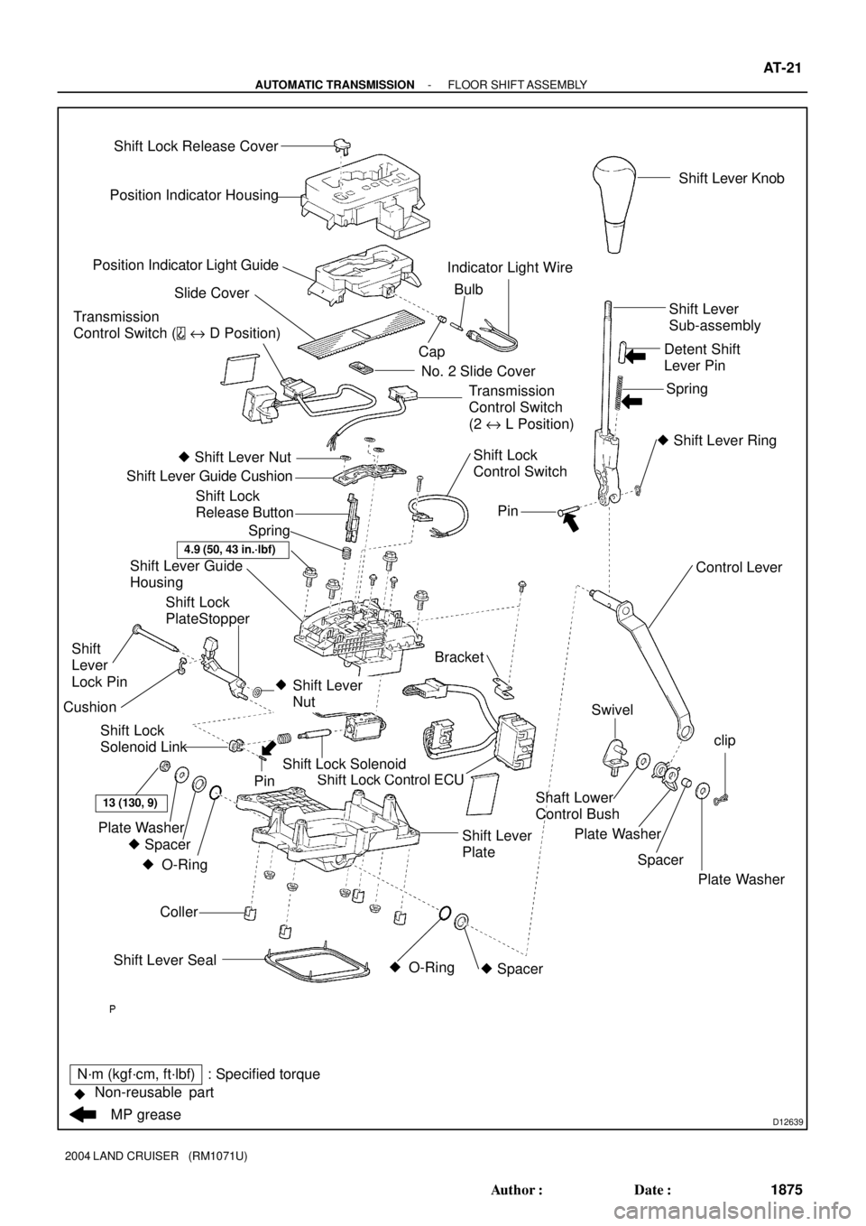
D12639
Position Indicator Housing
Position Indicator Light Guide
Slide Cover
No. 2 Slide Cover
� Shift Lever Nut
Shift Lever Guide Cushion
Shift Lever Guide
Housing
Bracket
Shift Lock Control ECU
Coller
13 (130, 9)
Plate Washer
� Spacer � O-Ring Shift Lever Seal� O-Ring � SpacerSwivel
Plate Washer
Spacer Shaft Lower
Control Bushclip
Plate Washer Control Lever
�
Pin
� Shift Lever Ring Spring Detent Shift
Lever PinShift Lever
Sub-assembly
Shift Lock Solenoid
Shift Lever
NutPinShift Lever Knob
Transmission
Control Switch (
e D Position)
Shift Lock
Control Switch CapBulb Indicator Light Wire
Shift Lock
Release Button
Spring
N´m (kgf´cm, ft´lbf) : Specified torque
�
MP grease Non-reusable partShift Lever
PlateTransmission
Control Switch
(2 e L Position)
Shift Lock
Solenoid Link
Shift
Lever
Lock Pin
4.9 (50, 43 in.´lbf)
Shift Lock Release Cover
Cushion
Shift Lock
PlateStopper
- AUTOMATIC TRANSMISSIONFLOOR SHIFT ASSEMBLY
AT-21
1875 Author�: Date�:
2004 LAND CRUISER (RM1071U)
Page 132 of 3115

DISASSEMBLY
1. REMOVE SHIFT LEVER KNOB
2. REMOVE POSITION INDICATOR HOUSING")
AT114-01
D12642
D12643
- AUTOMATIC TRANSMISSIONFLOOR SHIFT ASSEMBLY
AT-23
1877 Author�: Date�:
2004 LAND CRUISER (RM1071U)
DISASSEMBLY
1. REMOVE SHIFT LEVER KNOB
2. REMOVE POSITION INDICATOR HOUSING
(a) Using a small screwdriver, remove the shift lock release
cover from the position indicator housing.
(b) Remove the position indicator housing assembly.
3. REMOVE POSITION INDICATOR LIGHT GUIDE
(a) Disconnect the indicator lamp wire from the position indi-
cator light guide.
(b) Remove the position indicator light guide.
4. REMOVE SLIDE COVER AND NO. 2 SLIDE COVER
5. REMOVE SHIFT LEVER GUIDE HOUSING
(a) Disconnect the shift lock control ECU connector from the
shift lever plate.
(b) Disconnect the 2 transmission control switches and the
shift lock control switch from the shift lever guide housing.
(c) Remove the 4 bolts, nuts and the shift lever guide housing
assembly.
6. DISASSEMBLE SHIFT LEVER GUIDE HOUSING
(a) Using a screwdriver, pry up the 3 shift lever nuts.
(b) Using nippers, cut the 3 shift lever nuts off then.
HINT:
Remove the shift lever lock pin of the shift lever nut in the same
way.
(c) Remove the shift lever guide cushion.
(d) Remove the 3 screws, the shift lock control ECU and the
shift lock solenoid.
(e) Remove the shift lock control ECU bracket from the shift
lock control ECU.
(f) Disconnect the transmission control switch connector
from the shift lever guide housing.
(g) Remove the shift lock release button and the spring.
Page 137 of 3115

4. CONNECT SHIFT LOCK CONTROL ECU, SHIFT LOCK
SOLENOID, SHIFT LOCK CONTROL SWITCH, INDI-
CA")
D12642
- AUTOMATIC TRANSMISSIONFLOOR SHIFT ASSEMBLY
AT-27
1881 Author�: Date�:
2004 LAND CRUISER (RM1071U)
4. CONNECT SHIFT LOCK CONTROL ECU, SHIFT LOCK
SOLENOID, SHIFT LOCK CONTROL SWITCH, INDI-
CATOR LAMP WIRE AND 2 TRANSMISSION CON-
TROL SWITCH
5. REASSEMBLE SHIFT LEVER GUIDE HOUSING
(a) Apply MP grease to the shift lever lock pin.
(b) Install the shift lever lock pin, the shift lock plate stopper
and the cushion to the shift lever guide housing.
(c) Install a new shift lever nut to the shift lever lock pin by
knocking them lightly via the 10 mm seated nut.
HINT:
Install the shift lever guide cushion of the shift lever nut in the
same way.
(d) Apply MP grease to the shift lock release button.
(e) Install the spring and the shift lock release button.
(f) Connect the transmission control switch connector to the
shift lever guide housing.
(g) Install the shift lock control ECU bracket to the shift lock
control ECU.
(h) Install the shift lock control ECU and the shift lock sole-
noid with the 3 screws to the shift lever guide housing.
(i) Install the shift lever guide cushion with 3 new shift lever
nuts.
6. INSTALL SHIFT LEVER GUIDE HOUSING
(a) Install the shift lever guide housing assembly with the 4
bolts and nuts to the shift lever plate.
Torque: 4.9 N´m (50 kgf´cm, 43 in.´lbf)
(b) Install the 2 transmission control switches and the shift
lock control switch to the shift lever guide housing.
(c) Connect the shift lock control ECU connector to the shift
lever plate.
7. INSTALL SLIDE COVER AND NO. 2 SLIDE COVER
8. INSTALL POSITION INDICATOR LIGHT GUIDE
(a) Install the position indicator light guide.
(b) Connect the indicator lamp wire to the position indicator
light guide.
9. INSTALL POSITION INDICATOR HOUSING
(a) Install the position indicator housing.
(b) Install the shift lock release cover to the position indicator
housing.
10. INSTALL SHIFT LEVER KNOB
Page 143 of 3115
AT07Q-03
D12729
Key Interlock Solenoid
Stop Light Switch
Shift Lock Control ECU
Shift Lock Solenoid Bracket
- AUTOMATIC TRANSMISSIONSHIFT LOCK SYSTEM
AT-13
1867 Author�: Date�:
2004 LAND CRUISER (RM1071U)
SHIFT LOCK SYSTEM
LOCATION
Page 165 of 3115

BE2E9-01
I25054
ºTUNE DOWNº
Switchº4chº Switchº5chº Switch
º6chº Switch
ºTUNE UPº
Switch º1chº Switch
º2chº Switchº3chº Switch
ºDISCº Switch
- BODY ELECTRICALAUDIO SYSTEM
BE-129
2502 Author�: Date�:
2004 LAND CRUISER (RM1071U)
TROUBLESHOOTING
1. DIAGNOSIS FUNCTION (Main AVC-LAN)
(a) Diagnosis start-up
For shifting to diagnosis mode, turn the ignition switch ON and push the ºDISCº switch 3 times while
pressing ºch1º and ºch6º switches.
HINT:
To exit the diagnosis mode, push the ºDISCº switch for 1.7 sec. or turn the ignition switch to ACC or OFF.
(b) Element check mode
After the diagnosis start-up, the system enters the element check mode. Check that the all elements
light up.
HINT:
By pressing the ºTUNE UPº switch, the system enters the ºService Check Modeº.
(c) Switch check mode
(1) Element check mode is started at the same time with the switch check mode.
(2) Check that there is a beep sound when any switch is pressed.
HINT:
By pressing ºTUNE UPº switch, the system enters the ºService Check Modeº.
Page 171 of 3115
I25241
ºTUNE DOWNº Switch
ºTUNE UPº Switch
- BODY ELECTRICALAUDIO SYSTEM
BE-135
2508 Author�: Date�:
2004 LAND CRUISER (RM1071U)
2. DIAGNOSIS FUNCTION (Sub AVC-LAN)
HINT:
As starting Main AVC-LAN to operate the diagnosis mode, Sub AVC-LAN is automatically to the mode. Per-
form the diagnosis mode operation on the RSA panel.
(a) Element check mode
After the diagnosis start-up, the system enters the element check mode. Check that the all elements
light up.
HINT:
By pressing the ºTUNE UPº switch, the system enters the ºService Check Modeº.
(b) Switch check mode
(1) Element check mode is started at the same time with the switch check mode.
(2) Check that there is a beep sound when any switch is pressed.
HINT:
By pressing ºTUNE UPº switch, the system enters the ºService Check Modeº.
Page 204 of 3115

27 Noise NOISE PRODUCED BY VIBRATION OR SHOCK WHILE DRIVING
No
Ye s Is radio assembly properly installed?
Noise is produced from static eletricity accumulating in the vehicle body. With vehicles stationary lightly tap each system.
Is noise produced?Install properly.
Each system faulty. Is speaker properly installed?
No
No Ye s
Ye s
28 Noise NOISE PRODUCED WHEN ENGINE STARTS
NoYe s Whistling noise which becomes high-pitched when
accelerator strongly depressed, disappears shortly
after engine stops.Generator noise.
A/C noise.
Fuel gauge noise.
Horn noise.
Ignition noise.
Turn signal noise.
Washer noise.
Engine coolant temp. gauge noise.
Wiper noise. Whining noise occurs when A/C is operating.
Scratching noise occurs during sudden acceleration, driving on rough
roads or when ignition switch is turned ON.
Clicking sound is heard when horn button is pressed, then
released. Whirring/grating sound is heard when pushed
continuously.
Murmuring sound stops when engine stops.
Tick-tack noise occurs in co-ordination with blinking
offlasher.
Noise occurs during window washer operation.
Scratching noise occurs while engine is running,
and continues a while even after engine stops.
Scraping noise in line with wiper beat.
Other type of noiseYe s
Ye s
Ye s
Ye s
Ye s
Ye s
Ye s
Ye s No
No
No
No
No
No
No
No
BE-168
- BODY ELECTRICALAUDIO SYSTEM
2541 Author�: Date�:
2004 LAND CRUISER (RM1071U)