Page 1044 of 2389
Check wiring between ECU terminal T (T1) and check
connector terminal TE 1, and ECU
terminal E 1 and check connector terminal El. Is there diagnostic code output when check
connector terminals TE 1 and E 1 and short
circuited? Does ºCHECKº engine warning light come on when
ECU terminal W is grounded to the body?
Does ºCHECKº engine warning tight come
on when ignition switch is at ON?
Check bulb, fuse and wiring between ECU and
ignition switch.
Does ºCHECKº engine warning light go out after
repair according to malfunction code? Does ºCHECKº engine warning light go off when
the engine is started?
Check wiring between ECU and ºCHECKº
engine warning light.Check wiring between
ECU terminal El and body
ground.
Cancel out diagnostic code. Further repair required.Try another
ECU.Try another
ECU.
Repair or replace.Repair or replace.
System Normal
System Normal
System OKRepair.
BAD
BAD
BAD
YES YES
YESYES
YES
± EFI SYSTEMDiagnosis SystemFI±30
Page 1047 of 2389
ON±VEHICLE INSPECTION
1. CHECK FUEL PUMP OPERATION
(a) Turn the ignition switch ON.
NOTICE: Do not start the engine.
(b) Using SST, connect terminals +B and FP of the check con-
nector.
SST 09843±18020
(e) Turn the ignition switch OFF.
If there is no pressure, check the following
parts:
wFusible links
wFuses (ER 15 A, IGN 7.5 A)
wER main relay
wFuel pump
wECU
wWiring connections (e) Check that there is pressure in the hose from the fuel
filter.
HINT: At this time, you will hear fuel return noise.
(d) Remove SST.
SST 09843±18020
± EFI SYSTEMFuel System (Fuel Pump)FI±70
Page 1056 of 2389

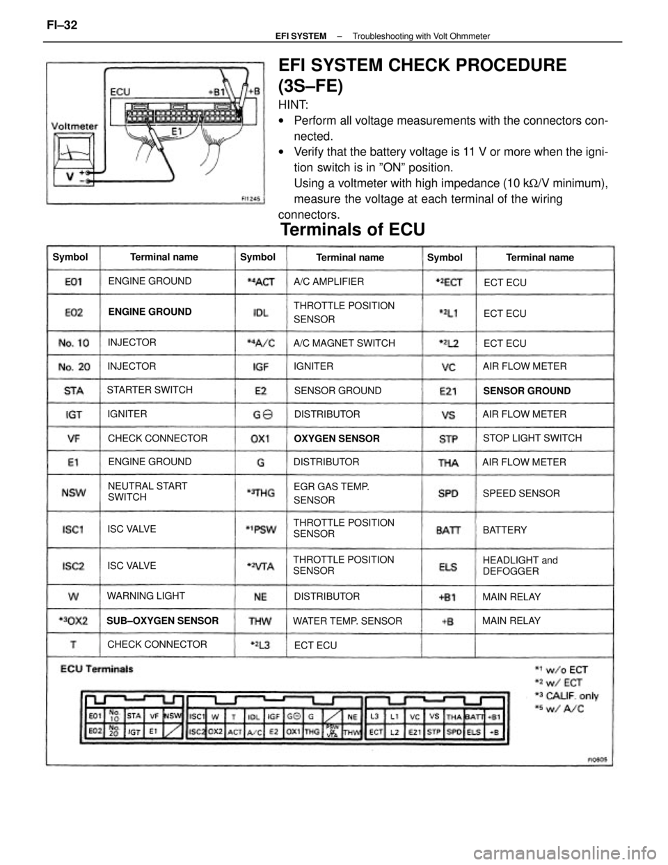
EFI SYSTEM CHECK PROCEDURE
(3S±FE)
HINT:
wPerform all voltage measurements with the connectors con-
nected.
wVerify that the battery voltage is 11 V or more when the igni-
tion switch is in ºONº position.
Using a voltmeter with high impedance (10 kW/V minimum),
measure the voltage at each terminal of the wiring
connectors.
THROTTLE POSITION
SENSORTHROTTLE POSITION
SENSOR
THROTTLE POSITION
SENSOR
Terminals of ECU
NEUTRAL START
SWITCH
HEADLIGHT and
DEFOGGER EGR GAS TEMP.
SENSOR
WATER TEMP. SENSOR SUB±OXYGEN SENSORA/C MAGNET SWITCH
STOP LIGHT SWITCH
CHECK CONNECTORCHECK CONNECTORAIR FLOW METER
AIR FLOW METER
AIR FLOW METER STARTER SWITCH
SENSOR GROUND SENSOR GROUND ENGINE GROUND
ENGINE GROUND ENGINE GROUND
OXYGEN SENSOR
WARNING LIGHTA/C AMPLIFIER
SPEED SENSORTerminal name Terminal name Terminal name
DISTRIBUTORDISTRIBUTOR
DISTRIBUTOR
MAIN RELAYMAIN RELAY ISC VALVE
ISC VALVE INJECTORINJECTOR Symbol
BATTERY Symbol
Symbol
IGNITERECT ECUECT ECU
ECT ECU
IGNITER
ECT ECU
± EFI SYSTEMTroubleshooting with Volt OhmmeterFI±32
Page 1057 of 2389
No trouble (ºCHECKº engine warning light off) and
engine running
Voltage at ECU Wiring Connectors (3S±FE)
Measuring plate fully closed
Intake air temp. 20°C (68°F)
Coolant temp. 80°C (1765F) Measuring plate fully open Throttle valve fully closed Throttle valve fully closed
Throttle valve open
Air conditioning ONThrottle valve open Throttle valve open
Cranking or idlingSTD voltage (V)
Terminals
3,000 rpmSee page Condition
IG SW ONIG SW ON
IG SW ON
IG
SW ONIG SW ON
IG SW ONCrankingIdling
FI±40
FI±44
FI±46FI±45FI±34
FI±43 FI±42
FI±47FI±35
FI±36
FI±37
FI±39
FI±41 No.
± EFI SYSTEMTroubleshooting with Volt OhmmeterFI±33
Page 1058 of 2389
Check that there is voltage between ECU terminal +B or +B1 and
body ground. (IG SW ON) No voltage between ECU terminals +B or +B1 and El.
(IG SW ON)
Check wiring between ECU terminal E1 and body
ground.
Check wiring between ER main
relay and battery.Check fuse, fusible link and
ignition switch.
Check ER main relay.Try another ECU.
Repair or replace. Repair or replace.
Repair or replace.
Ignition SW ON
STD voltageTerminals
Condition
Replace.
Trouble
BAD BADBAD
BAD No.
± EFI SYSTEMTroubleshooting with Volt OhmmeterFI±34
Page 1059 of 2389
Check that there is voltage between ECU terminal BATT and
body ground.
Check wiring between ECU terminal El and body
ground. No voltage between ECU terminals BATT and E1.
Check wiring between ECU
terminal and battery.Check fuse and fusible link.
Repair or replace.Repair or replace.
Try another ECU.STD voltage
No voltageCondition
Terminals
Replace. Trouble
BAD
BADBAD No.
± EFI SYSTEMTroubleshooting with Volt OhmmeterFI±35
Page 1060 of 2389
Check that there is voltage between ECU terminal + B or + B1 and body
ground. (IG SW ON) No voltage between ECU terminal 1D1. or PSW and E1.
(IG SW ON)
Check wiring between ECU terminal El and body
ground.
Check wiring between ECU and
throttle position sensor. Check throttle position sensor.
(See page FI±106)
Replace or repair throttle
position sensor. Refer to No. 1.
(See page FI±34) Throttle valve fully closedThrottle valve open
Repair or replace.
Repair or replace.
Try another ECU.STD voltage
No voltageIG SW ONCondition
TerminalsTrouble
BAD
BAD
BAD
BAD No.
± EFI SYSTEMTroubleshooting with Volt OhmmeterFI±36
Page 1061 of 2389
Check that there is voltage between ECU terminal +B or +B1 and body
ground. (IG SW 4111)
Check wiring between ECU terminal El and body
ground. No voltage between ECU terminals IDL and E2.
OG SW ON) (Throttle valve open)
Check wiring between ECU and
throttle position sensor. Check throttle position sensor.
(See page FI±110)
Repair or replace throttle
position sensor.Refer to No. 1.
(See page FI±34) Throttle valve fully closed
Throttle valve fully open
Try another ECU. Throttle valve open
Repair or replace.Repair or replace.
wIDL ± E2
STD voltage
No voltage
IG SW ON
Condition Terminals Trouble
BAD
BAD
BAD
BAD
No.
± EFI SYSTEMTroubleshooting with Volt OhmmeterFI±37