Page 793 of 2389

Heater Blower Switch
(Lever Type)
INSPECTION OF SWITCH
INSPECT SWITCH CONTINUITY
Inspect the heater blower switch continuity.
Control cables broken or binding
Servo motor faulty
Heater hoses leaking or clogged
Water valve faulty
Air dampers broken
Air ducts clogged
Heater radiator leaking or clogged
Heater control unit faulty Heater circuit breaker OFF
GAUGE fuse blown
Heater relay faulty
Blower speed control relay faulty
Heater blower switch faulty
Heater blower resistor faulty
Heater blower motor faulty wiring or
ground faultyReset breaker and check for short
Replace fuse and check for short
Check relay
Check control relay
Check switch
Check resistor
Check motor
Repair as necessary
Check cables
Check servo motor
Replace hoses
Replace water valve
Repair air dampers
Repair air ducts
Repair heater radiator
Repair control unit
*For illumination light
If continuity is not as specified, replace the switch.
Troubleshooting
BE±3
BE±3
BE±48
BE±50
BE±49
BE±48 Bolwer does not
work when fan
switch is on
Incorrect temperature
outputBE±3
BE±3
BE±48
Switch position Possible cause
BE±47
BE±48
Terminal Problem
Remedy
Lever
BE±52
Page
BE±54 Push
OFF
± BODY ELECTRICAL SYSTEMHeaterBE±47
Page 803 of 2389
DOOR LOCK CONTROL SYSTEM
Wiring and Connector Diagrams
Door Lock Manual Switch
(Driver's: in Master Switch)
Door Lock Motor Door Courtesy SwitchDoor Lock Control
Relay Door Key Lock and
Unlock SwitchKey Unlock
Warning Switch
(Front Passenger's)
± BODY ELECTRICAL SYSTEMDoor Lock Control SystemBE±57
Page 811 of 2389
AUTOMATIC SHOULDER BELT
Wiring Diagram
± BODY ELECTRICAL SYSTEMAutomatic Shoulder BeltBE±65
Page 827 of 2389
CRUISE CONTROL SYSTEM
Wiring Diagram
± BODY ELECTRICAL SYSTEMCruise Control SystemBE±69
Page 914 of 2389
WIRING DIAGRAM (2WD)
± BRAKE SYSTEMAnti±lock Brake System (A.B.S.)BR±63
Page 915 of 2389
WIRING DIAGRAM (4WD)
± BRAKE SYSTEMAnti±lock Brake System (A.B.S.)BR±64
Page 954 of 2389

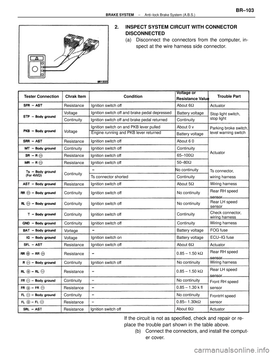
2. INSPECT SYSTEM CIRCUIT WITH CONNECTOR
DISCONNECTED
(a) Disconnect the connectors from the computer, in-
spect at the wire harness side connector.
If the circuit is not as specified, check and repair or re-
place the trouble part shown in the table above.
(b) Connect the connectors, and install the comput-
er cover.
Ignition switch off and brake pedal depressed
Engine running and PKB lever returned Ignition switch off and brake pedal returned
Ignition switch on and PKB lever pulled
Parking broke switch,
level warning switchStop light switch,
stop light Voltage or
Resistance Value
Check connector,
wiring harness
Front RH speed
sensor
FrontrH speed
sensor Ts connector,
wiring harness
Rear RH speed
sensor
Rear RH speed
sensor
Rear LH speed
sensorRear LH speed
sensor Ts connector shorted
Ignition switch offIgnition switch off
Ignition switch off
Ignition switch off Ignition switch off Tester Connection
Ignition switch offIgnition switch off
Ignition switch off
Ignition switch off Ignition switch off Ignition switch off
Ignition switch offIgnition switch off
Ignition switch onBattery voltage
No continuity
Battery voltage
0.85 ± 1.30 k fl
0.85± 1.30k� Battery voltage
Wiring harnessWiring harness
Wiring harness Battery voltage
0.85 ± 1.50 k� 0.85 ± 1.50 k�
No continuityNo continuity
No continuityNo continuityNo continuityTrouble Part
65±100�
ECU±IG fuse Chrak Item
50±80�
About 6� ContinuityResistance
Resistance
About 5� ResistanceAbout 6 0
Resistance
ResistanceAbout 6�
ResistanceContinuity Resistance
Resistance
ResistanceContinuity
ResistanceAbout 6�
ResistanceContinuity
Continuity
Continuity
ContinuityContinuity Continuity
Continuity Continuity
About 0 v
Continuity Continuity
Continuity
Continuity
FOG fuse Condition
ActuatorActuator
Actuator Voltage
VoltageVortege
Actuator Voltage
± BRAKE SYSTEMAnti±lock Brake System (A.B.S.)BR±103
Page 958 of 2389

PRECAUTIONS
1. Check that the battery cables are connected to the correct
terminals.
2. Disconnect the battery cables when the battery is given a
quick charge.
3. Do not perform tests with a high voltage insulation
resistance tester.
4. Never disconnect the battery when the engine is running.
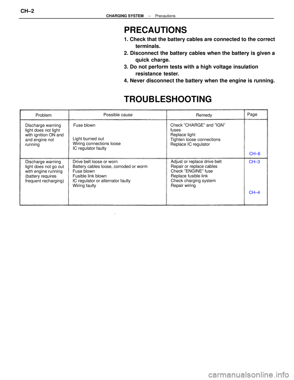
TROUBLESHOOTING
Drive belt loose or worn
Battery cables loose, corroded or worm
Fuse blown
Fusible link blown
IC regulator or alternator faulty
Wiring faultyAdjust or replace drive belt
Repair or replace cables
Check ºENGINEº fuse
Replace fusible link
Check charging system
Repair wiring Check ºCHARGEº and ºIGNº
fuses
Replace light
Tighten loose connections
Replace IC regulator
Discharge warning
light does not go out
with engine running
(battery requires
frequent recharging) Discharge warning
light does not light
with ignition ON and
and engine not
runningLight burned out
Wiring connections loose
IC regulator faultyPossible cause
Fuse blownRemedy
Problem
CH±6
CH±4 CH±3 Page
± CHARGING SYSTEMPrecautionsCH±2