Page 1842 of 2389

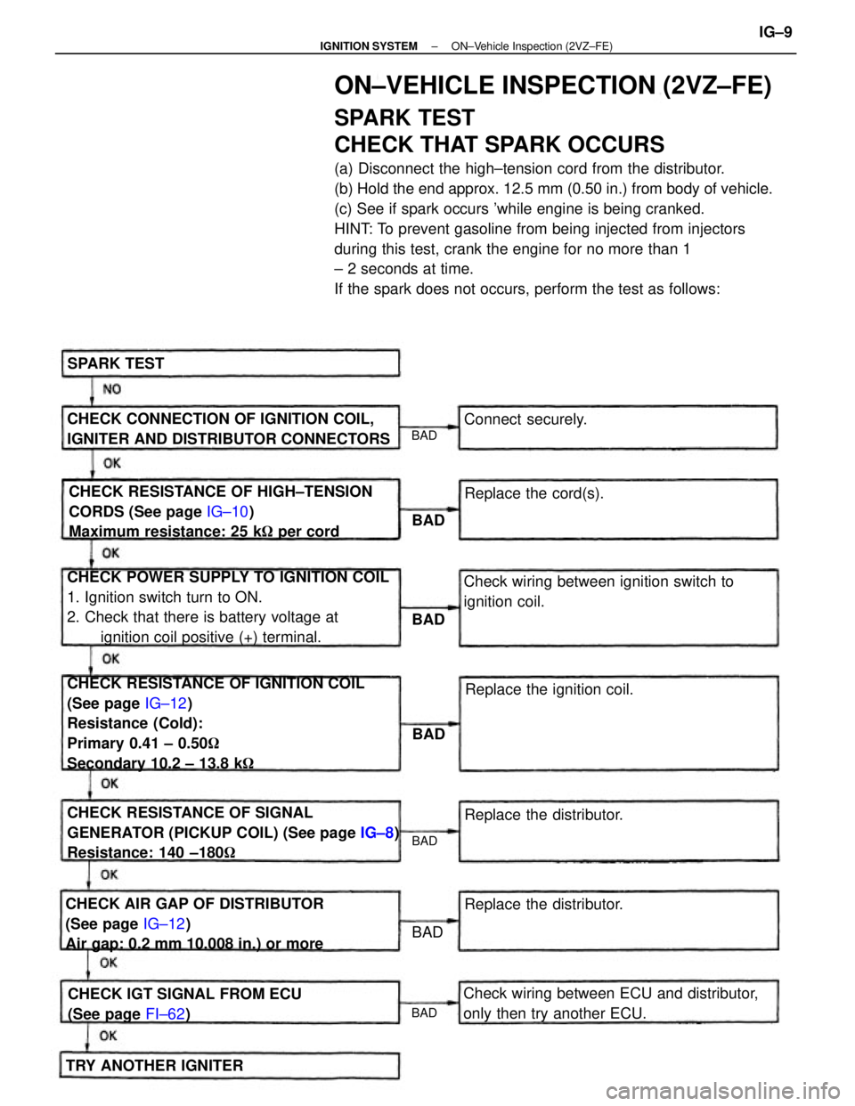
ON±VEHICLE INSPECTION (2VZ±FE)
SPARK TEST
CHECK THAT SPARK OCCURS
(a) Disconnect the high±tension cord from the distributor.
(b) Hold the end approx. 12.5 mm (0.50 in.) from body of vehicle.
(c) See if spark occurs 'while engine is being cranked.
HINT: To prevent gasoline from being injected from injectors
during this test, crank the engine for no more than 1
± 2 seconds at time.
If the spark does not occurs, perform the test as follows:
CHECK RESISTANCE OF IGNITION COIL
(See page IG±12)
Resistance (Cold):
Primary 0.41 ± 0.50�
Secondary 10.2 ± 13.8 k� CHECK POWER SUPPLY TO IGNITION COIL
1. Ignition switch turn to ON.
2. Check that there is battery voltage at
ignition coil positive (+) terminal.
CHECK RESISTANCE OF SIGNAL
GENERATOR (PICKUP COIL) (See page IG±8)
Resistance: 140 ±180� CHECK RESISTANCE OF HIGH±TENSION
CORDS (See page IG±10)
Maximum resistance: 25 k� per cord
CHECK AIR GAP OF DISTRIBUTOR
(See page IG±12)
Air gap: 0.2 mm 10.008 in.) or moreCHECK CONNECTION OF IGNITION COIL,
IGNITER AND DISTRIBUTOR CONNECTORS
Check wiring between ECU and distributor,
only then try another ECU.Check wiring between ignition switch to
ignition coil.
CHECK IGT SIGNAL FROM ECU
(See page FI±62)Replace the ignition coil.
Replace the distributor.
TRY ANOTHER IGNITERReplace the distributor. Replace the cord(s). Connect securely. SPARK TEST
BAD
BAD
BAD
BAD BAD
BAD
BAD
± IGNITION SYSTEMON±Vehicle Inspection (2VZ±FE)IG±9
Page 1858 of 2389

GENERAL REPAIR INSTRUCTIONS
1. Use fender seat and floor covers to keep the vehicle clean
and prevent damage.
2. During disassembly, keep parts in the appropriate order to
facilitate reassembly.
3. Observe the following:
(a) Before performing electrical work, disconnect the neg-
ative cable from the battery terminal.
(b) If it is necessary to disconnect the battery for inspection
or repair, always disconnect the cable from the nega-
tive H terminal which is grounded to the vehicle body.
(c) To prevent damage to the battery terminal post, loosen
the terminal nut and raise the cable straight up
without twisting or prying it.
(d) Clean the battery terminal posts and cable terminals
with a shop rag.
o not scrape them with a file or other
abrasive objects.
(e) Install the cable terminal to the battery post with
the nut loose, and tighten the nut after installation. Do
not use a hammer to tap the terminal onto the post.
(f) Be sure the cover for the positive (+) terminal is properly
in place.
4. Check hose and wiring connectors to make sure that they are
secure and correct.
5. Non±reusable parts
(a) Always replace cotter pins, gaskets, 0±rings and oil
seals etc. with new ones.
(b) Non±reusable parts are indicated in the component il-
lustrations by the ºrº symbol.
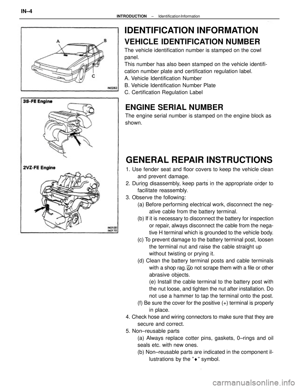
IDENTIFICATION INFORMATION
VEHICLE IDENTIFICATION NUMBER
The vehicle identification number is stamped on the cowl
panel.
This number has also been stamped on the vehicle identifi-
cation number plate and certification regulation label.
A. Vehicle Identification Number
B. Vehicle Identification Number Plate
C. Certification Regulation Label
ENGINE SERIAL NUMBER
The engine serial number is stamped on the engine block as
shown.
± INTRODUCTIONIdentification InformationIN±4
Page 1859 of 2389

GENERAL REPAIR INSTRUCTIONS
1. Use fender seat and floor covers to keep the vehicle clean
and prevent damage.
2. During disassembly, keep parts in the appropriate order to
facilitate reassembly.
3. Observe the following:
(a) Before performing electrical work, disconnect the neg-
ative cable from the battery terminal.
(b) If it is necessary to disconnect the battery for inspection
or repair, always disconnect the cable from the nega-
tive H terminal which is grounded to the vehicle body.
(c) To prevent damage to the battery terminal post, loosen
the terminal nut and raise the cable straight up
without twisting or prying it.
(d) Clean the battery terminal posts and cable terminals
with a shop rag.
o not scrape them with a file or other
abrasive objects.
(e) Install the cable terminal to the battery post with
the nut loose, and tighten the nut after installation. Do
not use a hammer to tap the terminal onto the post.
(f) Be sure the cover for the positive (+) terminal is properly
in place.
4. Check hose and wiring connectors to make sure that they are
secure and correct.
5. Non±reusable parts
(a) Always replace cotter pins, gaskets, 0±rings and oil
seals etc. with new ones.
(b) Non±reusable parts are indicated in the component il-
lustrations by the ºrº symbol.
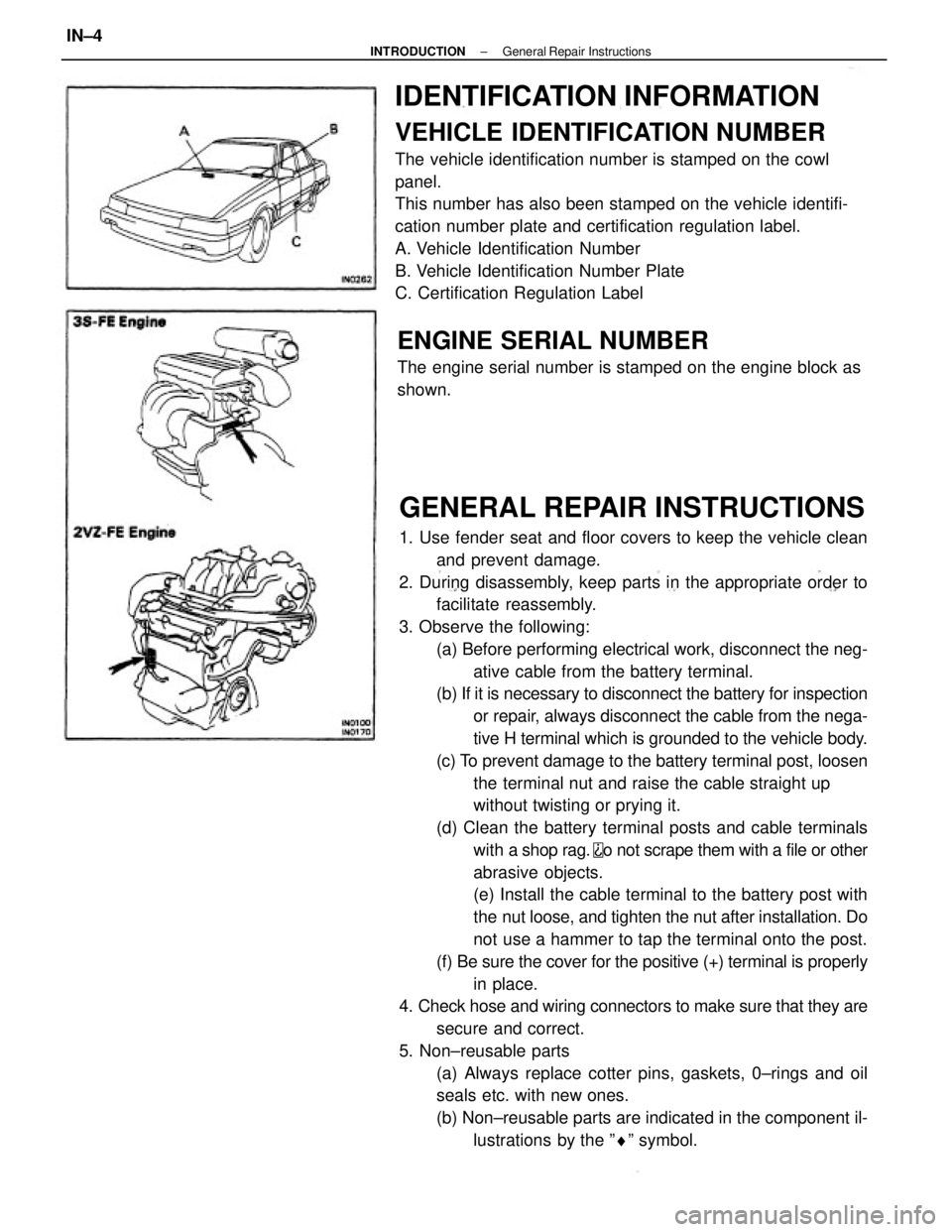
IDENTIFICATION INFORMATION
VEHICLE IDENTIFICATION NUMBER
The vehicle identification number is stamped on the cowl
panel.
This number has also been stamped on the vehicle identifi-
cation number plate and certification regulation label.
A. Vehicle Identification Number
B. Vehicle Identification Number Plate
C. Certification Regulation Label
ENGINE SERIAL NUMBER
The engine serial number is stamped on the engine block as
shown.
± INTRODUCTIONGeneral Repair InstructionsIN±4
Page 2043 of 2389
CENTER DIFFERENTIAL LOCK
CONTROL (E56F5)
SYSTEM DIAGRAM AND WIRING DIAGRAM
± MANUAL TRANSAXLECenter Differential Lock Control (E56F5)MT±113
Page 2299 of 2389
SST (SPECIAL SERVICE TOOLS) (Cont'd)
Remarks:
* 1 2VZ±FE only
* 2 E52 and E56F5
* 3 E56F5 only
* 4 Speedometer driven gear oil seal
* 5 FWD/VZV21 and 4WD Windshield Moulding
Remover
Altemator Pulley Set
Nut Wrench Set
Diagnosis Check
WiringAlternator Rear
Bearing PullerDoor Hinge Set
Bolt Wrench
Wiring º'Aº EFI
Inspection
Hexagon 8 mm
WrenchOil Pressure
Switch Socket
Back±up Light
Switch Tool
Wiring ªFº
EFI Inspection
Spring Tension Tool
IllustrationPart Name Section
Part No.
Puller Set
EM
RA
BO
± SST AND SSMSST (Special Service Tools)C±19
Page 2310 of 2389

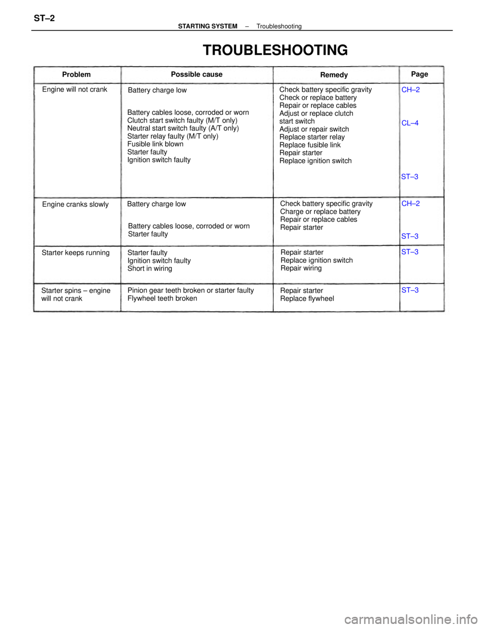
Check battery specific gravity
Check or replace battery
Repair or replace cables
Adjust or replace clutch
start switch
Adjust or repair switch
Replace starter relay
Replace fusible link
Repair starter
Replace ignition switch Battery cables loose, corroded or worn
Clutch start switch faulty (M/T only)
Neutral start switch faulty (A/T only)
Starter relay faulty (M/T only)
Fusible link blown
Starter faulty
Ignition switch faulty
Check battery specific gravity
Charge or replace battery
Repair or replace cables
Repair starter
Pinion gear teeth broken or starter faulty
Flywheel teeth brokenBattery cables loose, corroded or worn
Starter faulty
Repair starter
Replace ignition switch
Repair wiring Starter faulty
Ignition switch faulty
Short in wiring
TROUBLESHOOTING
Starter spins ± engine
will not crankRepair starter
Replace flywheel Engine will not crank
Starter keeps runningBattery charge low
Engine cranks slowlyBattery charge lowPossible cause
Remedy ProblemPage
CH±2
CH±2
ST±3 ST±3
ST±3
ST±3 CL±4
± STARTING SYSTEMTroubleshootingST±2