Page 1019 of 2389
PRECAUTIONS
1. Before working the fuel system, disconnect the cable
from negative (±) terminal of the battery.
HINT: Any diagnostic code retained by the computer will be erased
when the battery terminal is removed. Therefore, if necessary, read
the diagnosis before removing the battery terminal.
2. Do not smoke or work open flame when working the fuel system.
3. Keep gasoline off rubber or leather parts.
INSPECTION PRECAUTIONS
MAINTENANCE PRECAUTIONS
1. CHECK CORRECT ENGINE TUNE±UP
(See page EM±8)
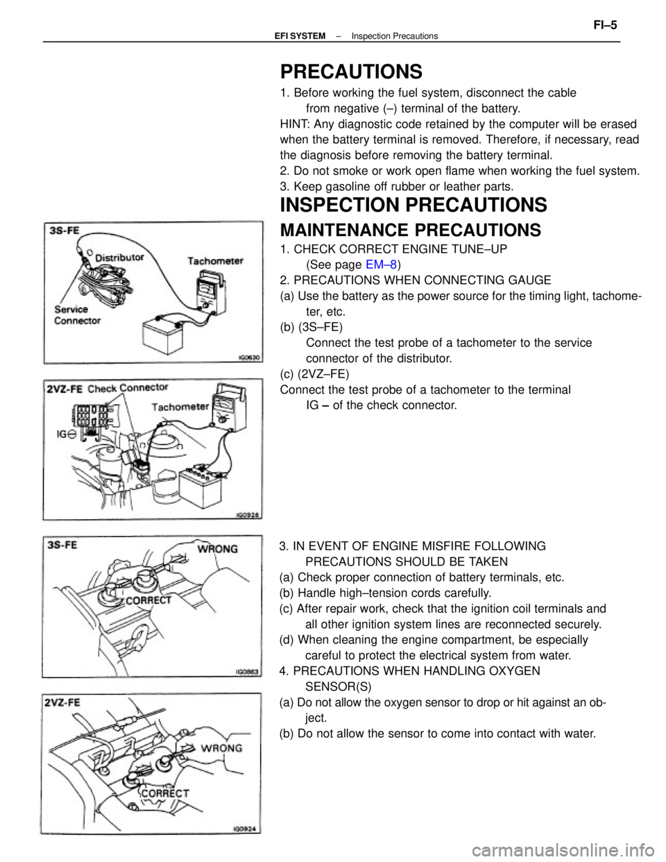
2. PRECAUTIONS WHEN CONNECTING GAUGE
(a) Use the battery as the power source for the timing light, tachome-
ter, etc.
(b) (3S±FE)
Connect the test probe of a tachometer to the service
connector of the distributor.
(c) (2VZ±FE)
Connect the test probe of a tachometer to the terminal
IG ± of the check connector.
3. IN EVENT OF ENGINE MISFIRE FOLLOWING
PRECAUTIONS SHOULD BE TAKEN
(a) Check proper connection of battery terminals, etc.
(b) Handle high±tension cords carefully.
(c) After repair work, check that the ignition coil terminals and
all other ignition system lines are reconnected securely.
(d) When cleaning the engine compartment, be especially
careful to protect the electrical system from water.
4. PRECAUTIONS WHEN HANDLING OXYGEN
SENSOR(S)
(a) Do not allow the oxygen sensor to drop or hit against an ob-
ject.
(b) Do not allow the sensor to come into contact with water.
± EFI SYSTEMInspection PrecautionsFI±5
Page 1020 of 2389
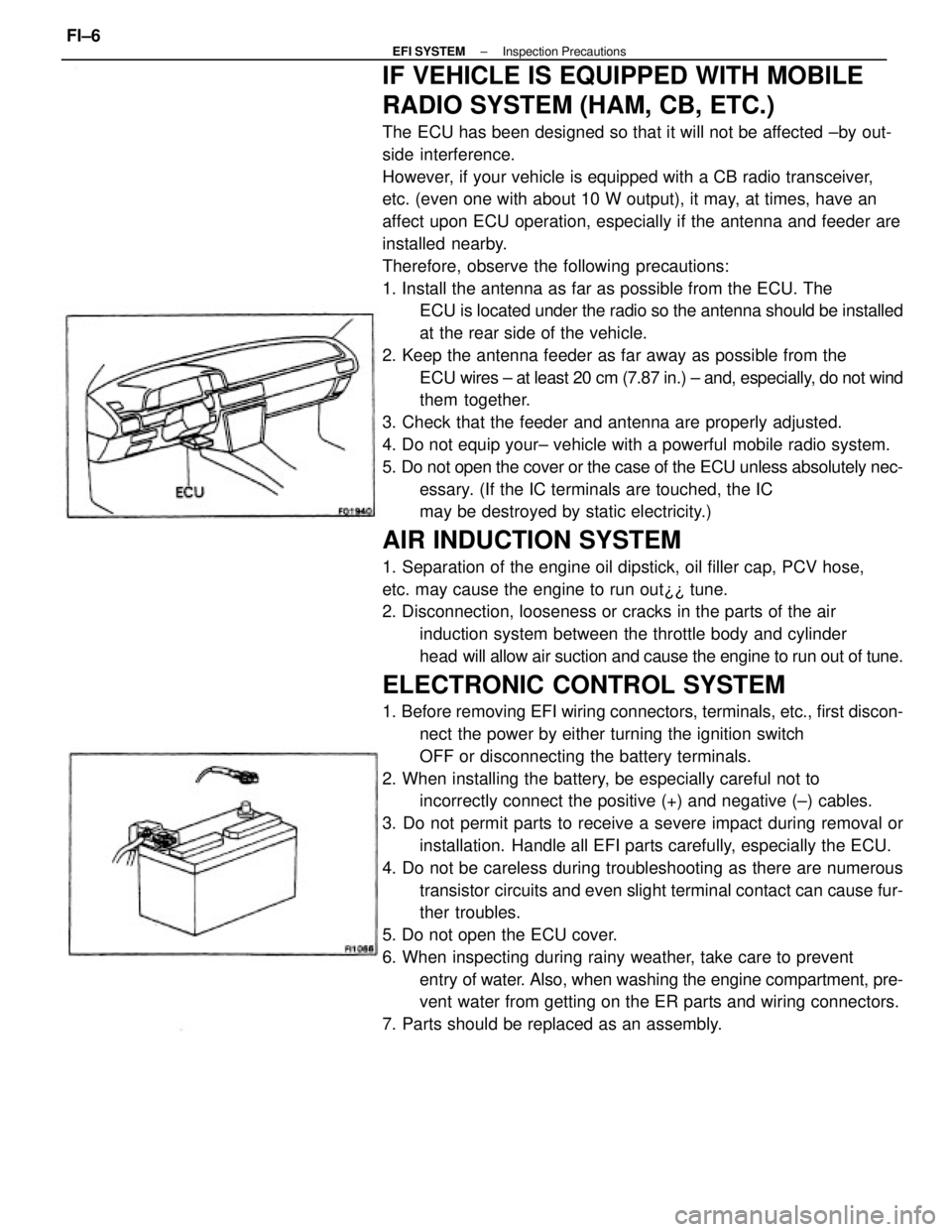
IF VEHICLE IS EQUIPPED WITH MOBILE
RADIO SYSTEM (HAM, CB, ETC.)
The ECU has been designed so that it will not be affected ±by out-
side interference.
However, if your vehicle is equipped with a CB radio transceiver,
etc. (even one with about 10 W output), it may, at times, have an
affect upon ECU operation, especially if the antenna and feeder are
installed nearby.
Therefore, observe the following precautions:
1. Install the antenna as far as possible from the ECU. The
ECU is located under the radio so the antenna should be installed
at the rear side of the vehicle.
2. Keep the antenna feeder as far away as possible from the
ECU wires ± at least 20 cm (7.87 in.) ± and, especially, do not wind
them together.
3. Check that the feeder and antenna are properly adjusted.
4. Do not equip your± vehicle with a powerful mobile radio system.
5. Do not open the cover or the case of the ECU unless absolutely nec-
essary. (If the IC terminals are touched, the IC
may be destroyed by static electricity.)
AIR INDUCTION SYSTEM
1. Separation of the engine oil dipstick, oil filler cap, PCV hose,
etc. may cause the engine to run out¿¿ tune.
2. Disconnection, looseness or cracks in the parts of the air
induction system between the throttle body and cylinder
head will allow air suction and cause the engine to run out of tune.
ELECTRONIC CONTROL SYSTEM
1. Before removing EFI wiring connectors, terminals, etc., first discon-
nect the power by either turning the ignition switch
OFF or disconnecting the battery terminals.
2. When installing the battery, be especially careful not to
incorrectly connect the positive (+) and negative (±) cables.
3. Do not permit parts to receive a severe impact during removal or
installation. Handle all EFI parts carefully, especially the ECU.
4. Do not be careless during troubleshooting as there are numerous
transistor circuits and even slight terminal contact can cause fur-
ther troubles.
5. Do not open the ECU cover.
6. When inspecting during rainy weather, take care to prevent
entry of water. Also, when washing the engine compartment, pre-
vent water from getting on the ER parts and wiring connectors.
7. Parts should be replaced as an assembly.
± EFI SYSTEMInspection PrecautionsFI±6
Page 1024 of 2389
TROUBLESHOOTING
TROUBLESHOOTING HINTS
1. Engine troubles is usually not caused by the EFI system.
When troubleshooting, always first check the condition of
the other systems.
(a) Electronic source
wBattery
wFusible links
wFuses
(b) Body ground
(e) Fuel supply
wFuel leakage
wFuel filter
wFuel pump
(d) Ignition system
wSpark plugs
wHigh±tension cords
wDistributor
wIgnition coil
wIgniter
(e) Air induction system
wVacuum leaks
(f) Emission control system
wPCV system
wEGR system
(g) Others
wIgnition timing (ESA system)
wdle speed (ISC system)
wetc.
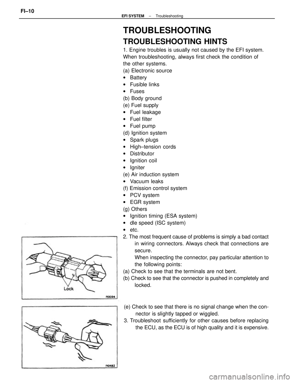
2. The most frequent cause of problems is simply a bad contact
in wiring connectors. Always check that connections are
secure.
When inspecting the connector, pay particular attention to
the following points:
(a) Check to see that the terminals are not bent.
(b) Check to see that the connector is pushed in completely and
locked.
(e) Check to see that there is no signal change when the con-
nector is slightly tapped or wiggled.
3. Troubleshoot sufficiently for other causes before replacing
the ECU, as the ECU is of high quality and it is expensive.
± EFI SYSTEMTroubleshootingFI±10
Page 1029 of 2389
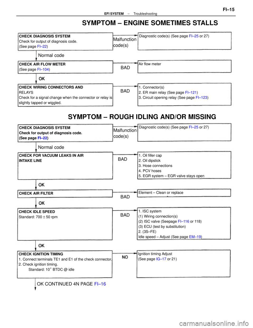
1. ISC system
(1) Wiring connection(s)
(2) ISC valve (Seepage FI±116 or 118)
(3) ECU (test by substitution)
2. (3S±FE)
Idle speed ± Adjust (See page EM±19)
CHECK IGNITION TIMING
1. Connect terminals TE1 and E1 of the check connector.
2. Check ignition timing.
Standard: 10° BTDC @ idle CHECK WIRING CONNECTORS AND
RELAYS
Check for a signal change when the connector or relay is
slightly tapped or wiggled.
1. Oil filler cap
2. Oil dipstick
3. Hose connections
4. PCV hoses
5. EGR system ± EGR valve stays open1. Connector(s)
2. ER main relay (See page FI±121)
3. Circuit opening relay (See page FI±123) CHECK DIAGNOSIS SYSTEM
Check for output of diagnosis code.
(See page FI±22)
CHECK DIAGNOSIS SYSTEM
Check for output of diagnosis code.
(See page FI±22)
SYMPTOM ± ENGINE SOMETIMES STALLS
SYMPTOM ± ROUGH IDLING AND/OR MISSING
CHECK FOR VACUUM LEAKS IN AIR
INTAKE LINE
Ignition timing Adjust
(See page IG±17 or 21) CHECK AIR FLOW METER
(See page FI±104)
CHECK IDLE SPEED
Standard: 700 + 50 rpmDiagnostic code(s) (See page FI±25 or 27)
Diagnostic code(s) (See page FI±25 or 27)
OK CONTINUED 4N PAGE FI±16
Element ± Clean or replace
CHECK AIR FILTER
Malfunction
code(s)
Malfunction
code(s)
Air flow meter
Normal code
Normal code
BAD
BADBAD
BAD BAD
± EFI SYSTEMTroubleshootingFI±15
Page 1036 of 2389
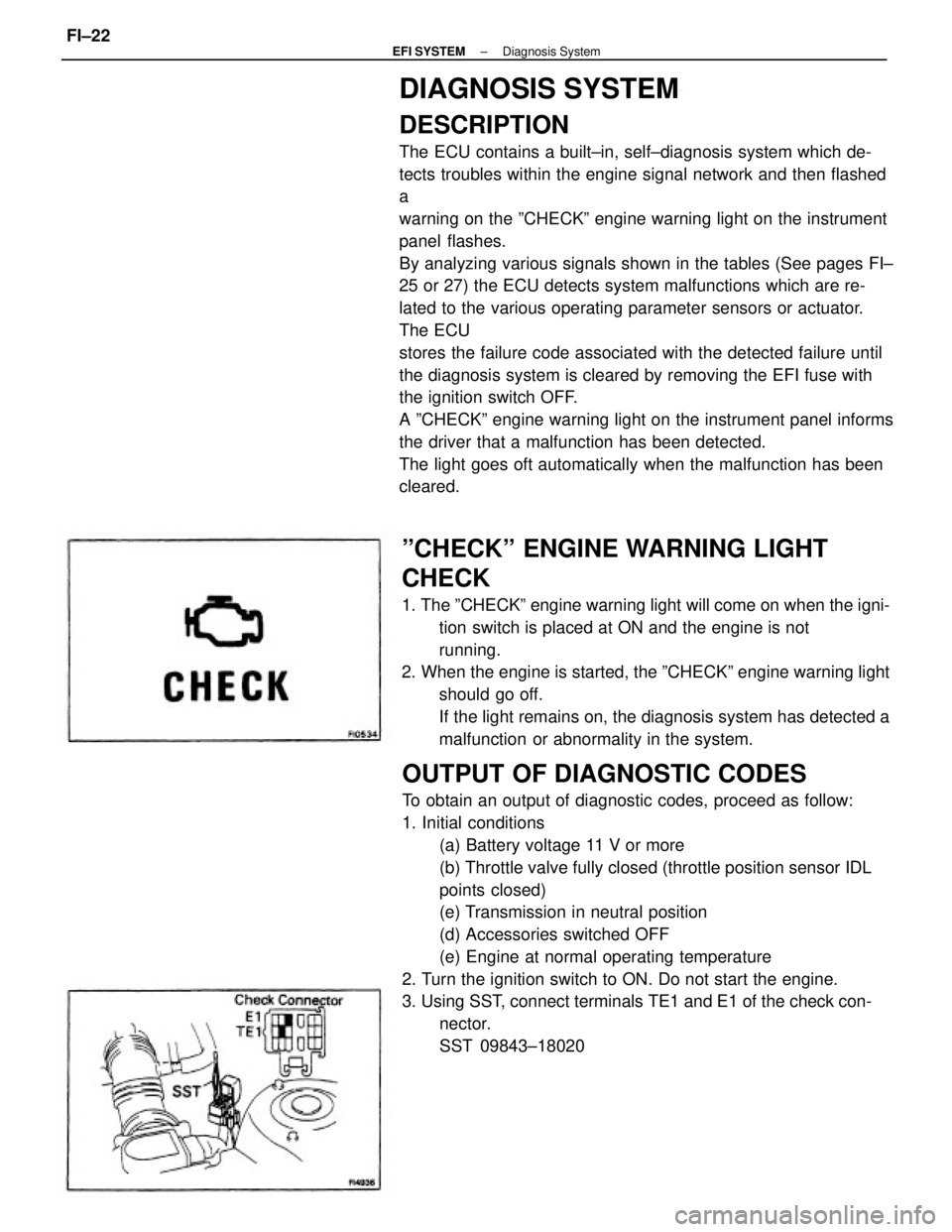
DIAGNOSIS SYSTEM
DESCRIPTION
The ECU contains a built±in, self±diagnosis system which de-
tects troubles within the engine signal network and then flashed
a
warning on the ºCHECKº engine warning light on the instrument
panel flashes.
By analyzing various signals shown in the tables (See pages FI±
25 or 27) the ECU detects system malfunctions which are re-
lated to the various operating parameter sensors or actuator.
The ECU
stores the failure code associated with the detected failure until
the diagnosis system is cleared by removing the EFI fuse with
the ignition switch OFF.
A ºCHECKº engine warning light on the instrument panel informs
the driver that a malfunction has been detected.
The light goes oft automatically when the malfunction has been
cleared.
OUTPUT OF DIAGNOSTIC CODES
To obtain an output of diagnostic codes, proceed as follow:
1. Initial conditions
(a) Battery voltage 11 V or more
(b) Throttle valve fully closed (throttle position sensor IDL
points closed)
(e) Transmission in neutral position
(d) Accessories switched OFF
(e) Engine at normal operating temperature
2. Turn the ignition switch to ON. Do not start the engine.
3. Using SST, connect terminals TE1 and E1 of the check con-
nector.
SST 09843±18020
ºCHECKº ENGINE WARNING LIGHT
CHECK
1. The ºCHECKº engine warning light will come on when the igni-
tion switch is placed at ON and the engine is not
running.
2. When the engine is started, the ºCHECKº engine warning light
should go off.
If the light remains on, the diagnosis system has detected a
malfunction or abnormality in the system.
± EFI SYSTEMDiagnosis SystemFI±22
Page 1037 of 2389
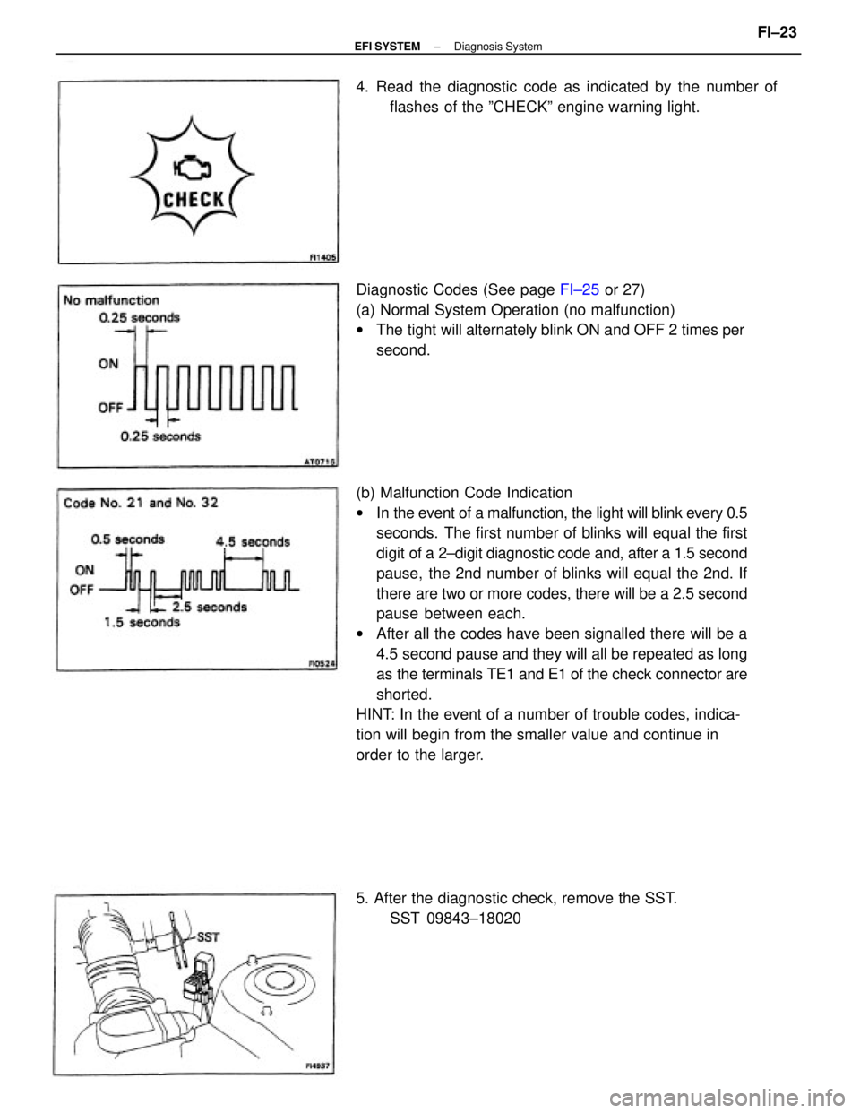
(b) Malfunction Code Indication
wIn the event of a malfunction, the light will blink every 0.5
seconds. The first number of blinks will equal the first
digit of a 2±digit diagnostic code and, after a 1.5 second
pause, the 2nd number of blinks will equal the 2nd. If
there are two or more codes, there will be a 2.5 second
pause between each.
wAfter all the codes have been signalled there will be a
4.5 second pause and they will all be repeated as long
as the terminals TE1 and E1 of the check connector are
shorted.
HINT: In the event of a number of trouble codes, indica-
tion will begin from the smaller value and continue in
order to the larger. Diagnostic Codes (See page FI±25 or 27)
(a) Normal System Operation (no malfunction)
wThe tight will alternately blink ON and OFF 2 times per
second. 4. Read the diagnostic code as indicated by the number of
flashes of the ºCHECKº engine warning light.
5. After the diagnostic check, remove the SST.
SST 09843±18020
± EFI SYSTEMDiagnosis SystemFI±23
Page 1038 of 2389
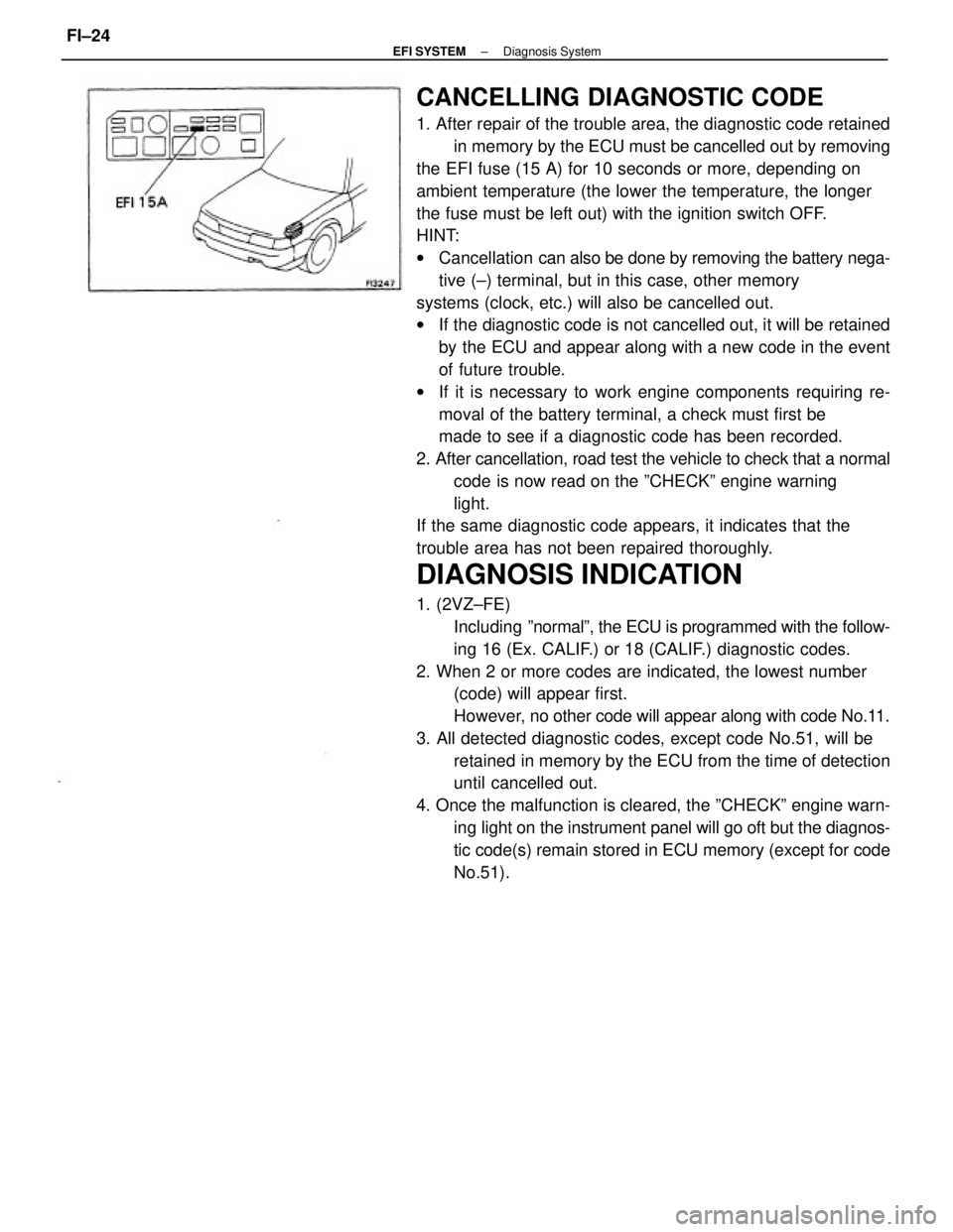
CANCELLING DIAGNOSTIC CODE
1. After repair of the trouble area, the diagnostic code retained
in memory by the ECU must be cancelled out by removing
the EFI fuse (15 A) for 10 seconds or more, depending on
ambient temperature (the lower the temperature, the longer
the fuse must be left out) with the ignition switch OFF.
HINT:
wCancellation can also be done by removing the battery nega-
tive (±) terminal, but in this case, other memory
systems (clock, etc.) will also be cancelled out.
wIf the diagnostic code is not cancelled out, it will be retained
by the ECU and appear along with a new code in the event
of future trouble.
wIf it is necessary to work engine components requiring re-
moval of the battery terminal, a check must first be
made to see if a diagnostic code has been recorded.
2. After cancellation, road test the vehicle to check that a normal
code is now read on the ºCHECKº engine warning
light.
If the same diagnostic code appears, it indicates that the
trouble area has not been repaired thoroughly.
DIAGNOSIS INDICATION
1. (2VZ±FE)
Including ºnormalº, the ECU is programmed with the follow-
ing 16 (Ex. CALIF.) or 18 (CALIF.) diagnostic codes.
2. When 2 or more codes are indicated, the lowest number
(code) will appear first.
However, no other code will appear along with code No.11.
3. All detected diagnostic codes, except code No.51, will be
retained in memory by the ECU from the time of detection
until cancelled out.
4. Once the malfunction is cleared, the ºCHECKº engine warn-
ing light on the instrument panel will go oft but the diagnos-
tic code(s) remain stored in ECU memory (except for code
No.51).
± EFI SYSTEMDiagnosis SystemFI±24
Page 1044 of 2389
Check wiring between ECU terminal T (T1) and check
connector terminal TE 1, and ECU
terminal E 1 and check connector terminal El. Is there diagnostic code output when check
connector terminals TE 1 and E 1 and short
circuited? Does ºCHECKº engine warning light come on when
ECU terminal W is grounded to the body?
Does ºCHECKº engine warning tight come
on when ignition switch is at ON?
Check bulb, fuse and wiring between ECU and
ignition switch.
Does ºCHECKº engine warning light go out after
repair according to malfunction code? Does ºCHECKº engine warning light go off when
the engine is started?
Check wiring between ECU and ºCHECKº
engine warning light.Check wiring between
ECU terminal El and body
ground.
Cancel out diagnostic code. Further repair required.Try another
ECU.Try another
ECU.
Repair or replace.Repair or replace.
System Normal
System Normal
System OKRepair.
BAD
BAD
BAD
YES YES
YESYES
YES
± EFI SYSTEMDiagnosis SystemFI±30