Page 741 of 2389

BODY DIMENSIONS
General Information
1. BASIC DIMENSIONS
(a) There are two types of dimensions in the diagram.
wStraight±line distance between the center of two
measuring points.
HINT:
1. The height of the left and right pointers must be equal.
2. Always calibrate the tracking gauge before measuring
or after adjusting the pointer height.
3. Take care not to drop the tracking gauge or otherwise
shock it.
4. Confirm that the pointers are securely in the holes. 2. MEASURING
(a) Basically, all measurements are to be done with a
tracking gauge. For portion where it is not possible to
use a tracking gauge, a tape measure should be
used.
(b) Use only a tracking gauge that has no looseness in
the body, measuring plate, or pointers. wThe height from an imaginary standard line.
(b) In cases i n which only one dimension is given, left
and right are symmetrical.
(c) The dimensions in the following drawing indicate ac-
tual distance. Therefore, please use the dimensions
as a reference.
(e) When using a tape measure, avoid twists and bends
in the tape.
(d) When tracking a diagonal measurement from the front
spring support inner hole to the suspension member
upper rear installation hole, measure along the front
spring support panel surface.
± BODYBody DimensionsBO±75
Page 742 of 2389
BODY DIMENSIONS
ENGINE COMPARTMENT
Front crossmember bumper installation nut Front side member bumper installation hole
Front side member standard hole Front spring support inner hole
Cowl top panel standard hole Cowl top panel center mark
Tube clamp installation nut Front fender installation nut
Headlight installation hole Front fender installation nut
Fender installation nut
Name
± BODYBody DimensionsBO±76
Page 757 of 2389
Fuses
1. GAUGE
2. ±
3. STOP
4. TAIL
5. CIG
6. RADIO
7. TURN
8. DEF±I/UP
9. ±
10. ENGINE
11. WIPER
12. ECU±IG
13. ±
14. IGN
15. ECU±B FUSE AND RELAY BLOCK No±1 (LOCATION: Driver's Side Kick Panel)7.5A
20A
15A
15A
7.5A
7.5A
10A
10A
20A
15A
7.5A
1 0A
FUSE AND RELAY BLOCKS
± BODY ELECTRICAL SYSTEMLocation of Switches and RelaysBE±11
Page 857 of 2389

CHECKS AND ADJUSTMENTS
CHECK AND ADJUSTMENT OF BRAKE
PEDAL
1. CHECK THAT PEDAL HEIGHT IS CORRECT
Pedal height from asphalt sheet:
177.5 ± 187.5 mm (6.988 ± 7.382 in.)
If incorrect, adjust the pedal height.
2. IF NECESSARY, ADJUST PEDAL HEIGHT
(a) If necessary, remove the instrument lower finish pan-
el and air duct.
(b) Loosen the stop light switch lock nut.
(e) Sufficiently loosen the stop light switch.
(d) Loosen the push rod lock nut.
(e) Adjust the pedal height by turning the pedal push
rod.
(f) Return the stop light switch until it lightly contacts the
pedal stopper.
(g) Tighten the two lock nuts.
(h) Check that the stop lights light when the brake pedal
depressed.
(i) After adjusting the pedal height, check and adjust
the pedal freeplay.
3. CHECK THAT PEDAL FREEPLAY IS CORRECT
(a) Stop the engine and depress the brake pedal sever-
al times until there is no more vacuum left in the
booster.
(b) Push in the pedal until the beginning of resistance
is felt. Measure the distance, as shown.
Pedal freeplay: 3 ±6 mm (0.12 ± 0.24 in.)
HINT: The freeplay to the first resistance is due to the play
between the clevis and pin. And it is 1 3 mm (0.04±
0.12 in.) on the pedal.
4. IF NECESSARY, ADJUST PEDAL FREEPLAY
(a) If incorrect, adjust the pedal freeplay by turning the
pedal push rod.
(b) Start the engine and confirm that pedal freepiay ex-
ists.
(e) After adjusting the pedal freeplay, check the pedal
height.
(d) Install the air duct and instrument lower finish panel.
± BRAKE SYSTEMChecks and AdjustmentsBR±6
Page 867 of 2389
INSTALLATION OF BRAKE BOOSTER
(See page BR±15)
1. ADJUST LENGTH OF BOOSTER PUSH ROD
(a) Set the SST on the master cylinder with the gasket,
and then lower the pin until its slightly touches the
piston.
SST 09737±00010
3. CONNECT CLEVIS TO BRAKE PEDAL
Insert the clevis pin into the clevis and brake pedal, and
install the clip to the clevis pin.
4. INSTALL PEDAL RETURN SPRING
5. INSTALL INSTRUMENT LOWER FINISH PANEL(b) Turn the SST upside down and set it on the booster.
SST 49737±00010
(c) Measure the clearance between the booster push
rod and pin head (SST).
Clearance: 0 mm (0 in.)
2. INSTALL BRAKE BOOSTER, GASKET AND CLEVIS
(a) Install the clevis lock nut and clevis to the brake
booster.
(b) Install the brake booster and gasket.
(c) Install and torque the booster mounting nuts.
Torque: 130 kg±cm (9 ft±Ib, 13 N¿ m)
(d) Adjust the booster push rod length until the push rod
lightly touches the pin head.
± BRAKE SYSTEMBrake BoosterBR±16
Page 976 of 2389

CHECK AND ADJUSTMENT OF
CLUTCH PEDAL
1. CHECK THAT PEDAL HEIGHT IS CORRECT
Pedal height from asphalt shaft 181 ± 191 mm
(7:13 ± 7.52 in.)
2. IF NECESSARY, ADJUST PEDAL HEIGHT
(a) Remove the instrument lower finish panel and discon-
nect the air duct.
(b) Loosen the lock nut and turn the stopper bolt (w/o
Cruise control system) or clutch switch (w/ Cruise
control system) until the height is correct. Tighten the
lock nut.
HINT: Before rotating the clutch switch for pedal height
adjustment, disconnect the clutch switch connector.
3. CHECK THAT PEDAL FREEPLAY AND PUSH ROD
PLAY ARE CORRECT
(Pedal Freeplay)
Push in the pedal until the beginning of clutch resistance
is felt.
Pedal freeplay: 5 ± 15 mm (0.20 ± 0.59 in.)
Push rod play at pedal top: 1.0 ± 5.0 mm
(0.039 ± 0.197 in.)
4. IF NECESSARY, ADJUST PEDAL FREEPLAY AND
PUSH ROD PLAY
(a) Loosen the lock nut and turn the push rod until the free-
play and push rod play are correct.
(b) Tighten the lock nut.
(e) After adjusting the pedal freeplay, check the pedal
height.
(d) Connect the air duct and install the lower finish panel.
5. INSPECT CLUTCH RELEASE POINT
(a) Pull the parking brake lever and install wheel stopper.
(b) Start the engine and idle the engine.
(e) Without depressing the clutch pedal, slowly shift the
shift lever into reverse position until the gears contact.
(d) Gradually depress the clutch pedal and measure the
stroke distance from the point the gear noise stops
(release point) up to the full stroke end position.
Standard distance: 25 mm (0.98 in.) or more
(From pedal stroke end position to release point)
If the distance is not as specified, perform the following
operation.
wInspect pedal height.
wInspect push rod play and pedal free play.
wBleed the clutch line.
wInspect the clutch cover and disc.
± CLUTCHCheck and Adjustment of Clutch PedalCL±3
Page 979 of 2389
REMOVAL OF MASTER CYLINDER
1. DRAW OUT FLUID WITH SYRINGE
2. DISCONNECT CLUTCH LINE TUBE
3. REMOVE INSTRUMENT LOWER FINISH PANEL
Remove the lower instrument lower finish panel and disconnect
the air duct from the instrument lower finish panel.
4. REMOVE CLEVIS PIN AND CLIP WITH SPRING
WASHER
Remove the clip and clevis pin with the spring washer.
5. REMOVE MOUNTING NUTS AND PULL OUT MASTER
CYLINDER
DISASSEMBLY OF MASTER CYLINDER
1. REMOVE RESERVOIR TANK
2. REMOVE PUSH ROD AND PISTON
(a) Pull back the boot and, using snap ring pliers, remove the snap
ring.
(b) Pull out the push rod.
CLUTCH MASTER CYLINDER
COMPONENTS
± CLUTCHClutch Master CylinderCL±5
Page 980 of 2389
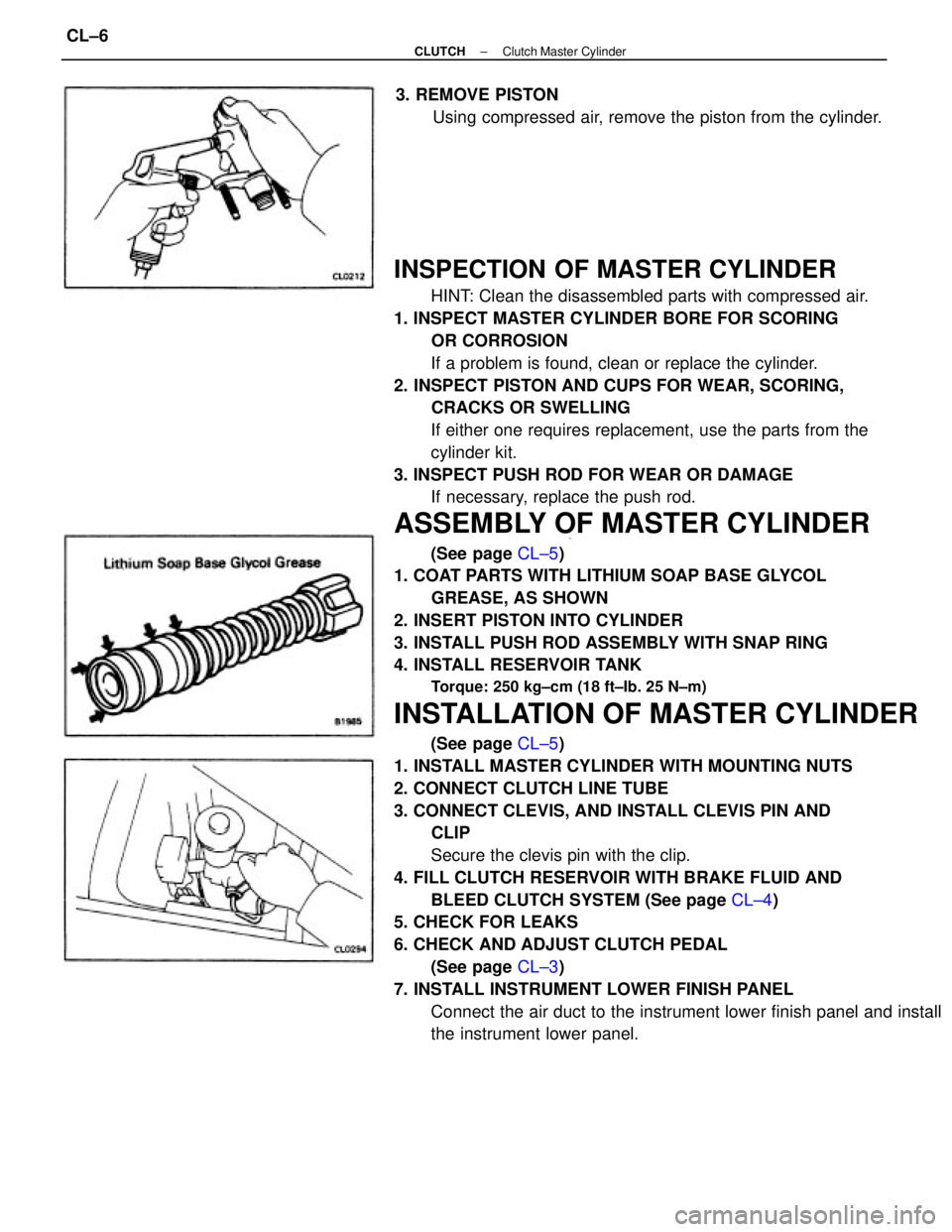
INSPECTION OF MASTER CYLINDER
HINT: Clean the disassembled parts with compressed air.
1. INSPECT MASTER CYLINDER BORE FOR SCORING
OR CORROSION
If a problem is found, clean or replace the cylinder.
2. INSPECT PISTON AND CUPS FOR WEAR, SCORING,
CRACKS OR SWELLING
If either one requires replacement, use the parts from the
cylinder kit.
3. INSPECT PUSH ROD FOR WEAR OR DAMAGE
If necessary, replace the push rod.
ASSEMBLY OF MASTER CYLINDER
(See page CL±5)
1. COAT PARTS WITH LITHIUM SOAP BASE GLYCOL
GREASE, AS SHOWN
2. INSERT PISTON INTO CYLINDER
3. INSTALL PUSH ROD ASSEMBLY WITH SNAP RING
4. INSTALL RESERVOIR TANK
Torque: 250 kg±cm (18 ft±Ib. 25 N±m)
INSTALLATION OF MASTER CYLINDER
(See page CL±5)
1. INSTALL MASTER CYLINDER WITH MOUNTING NUTS
2. CONNECT CLUTCH LINE TUBE
3. CONNECT CLEVIS, AND INSTALL CLEVIS PIN AND
CLIP
Secure the clevis pin with the clip.
4. FILL CLUTCH RESERVOIR WITH BRAKE FLUID AND
BLEED CLUTCH SYSTEM (See page CL±4)
5. CHECK FOR LEAKS
6. CHECK AND ADJUST CLUTCH PEDAL
(See page CL±3)
7. INSTALL INSTRUMENT LOWER FINISH PANEL
Connect the air duct to the instrument lower finish panel and install
the instrument lower panel. 3. REMOVE PISTON
Using compressed air, remove the piston from the cylinder.
± CLUTCHClutch Master CylinderCL±6


