Page 1006 of 2389
6. CHECK FOR WATER LEAKS
(a) Tighten the drain plug.
(b) Plug the inlet and outlet pipes of the radiator with SST.
SST 09230=00010
(c) Using a radiator cap tester, apply pressure to the radiator.
Test pressure: 1.8 kg/cm
2 (26 psi, 177 kPa) HINT:
wStake with just enough pressure to leave a mark on the
claw. The staked plate height (H) should be as follows:
Plate height (H):
9.0±9.4 mm (0.354±0.370in.)
NOTICE: If the bottom of the core plate is staked with
the SST on the guide block stopper, it may result in
water leakage.
wThe points shown i n the illustration cannot be staked
with the SST. Use pliers and be careful not to damage
the core plates. wDo not stake the areas protruding around the pipes,
brackets or tank ribs.
± COOLING SYSTEMRadiatorCO±19
Page 1240 of 2389

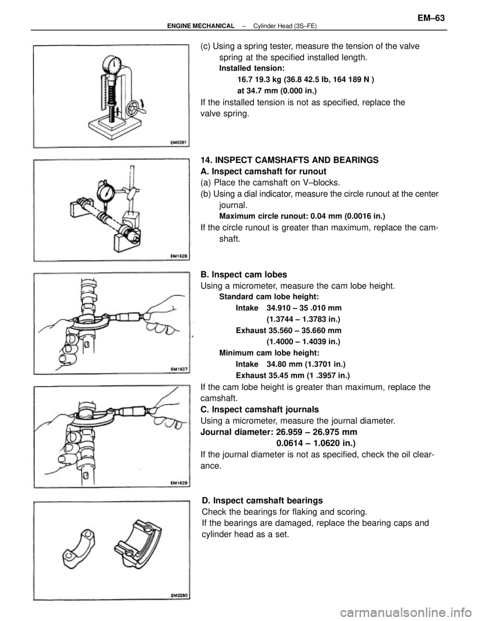
B. Inspect cam lobes
Using a micrometer, measure the cam lobe height.
Standard cam lobe height:
Intake 34.910 ± 35 .010 mm
(1.3744 ± 1.3783 in.)
Exhaust 35.560 ± 35.660 mm
(1.4000 ± 1.4039 in.)
Minimum cam lobe height:
Intake 34.80 mm (1.3701 in.)
Exhaust 35.45 mm (1 .3957 in.)
If the cam lobe height is greater than maximum, replace the
camshaft.
C. Inspect camshaft journals
Using a micrometer, measure the journal diameter.
Journal diameter: 26.959 ± 26.975 mm
0.0614 ± 1.0620 in.)
If the journal diameter is not as specified, check the oil clear-
ance. 14. INSPECT CAMSHAFTS AND BEARINGS
A. Inspect camshaft for runout
(a) Place the camshaft on V±blocks.
(b) Using a dial indicator, measure the circle runout at the center
journal.
Maximum circle runout: 0.04 mm (0.0016 in.)
If the circle runout is greater than maximum, replace the cam-
shaft. (c) Using a spring tester, measure the tension of the valve
spring at the specified installed length.
Installed tension:
16.7 19.3 kg (36.8 42.5 Ib, 164 189 N )
at 34.7 mm (0.000 in.)
If the installed tension is not as specified, replace the
valve spring.
D. Inspect camshaft bearings
Check the bearings for flaking and scoring.
If the bearings are damaged, replace the bearing caps and
cylinder head as a set.
± ENGINE MECHANICALCylinder Head (3S±FE)EM±63
Page 1268 of 2389

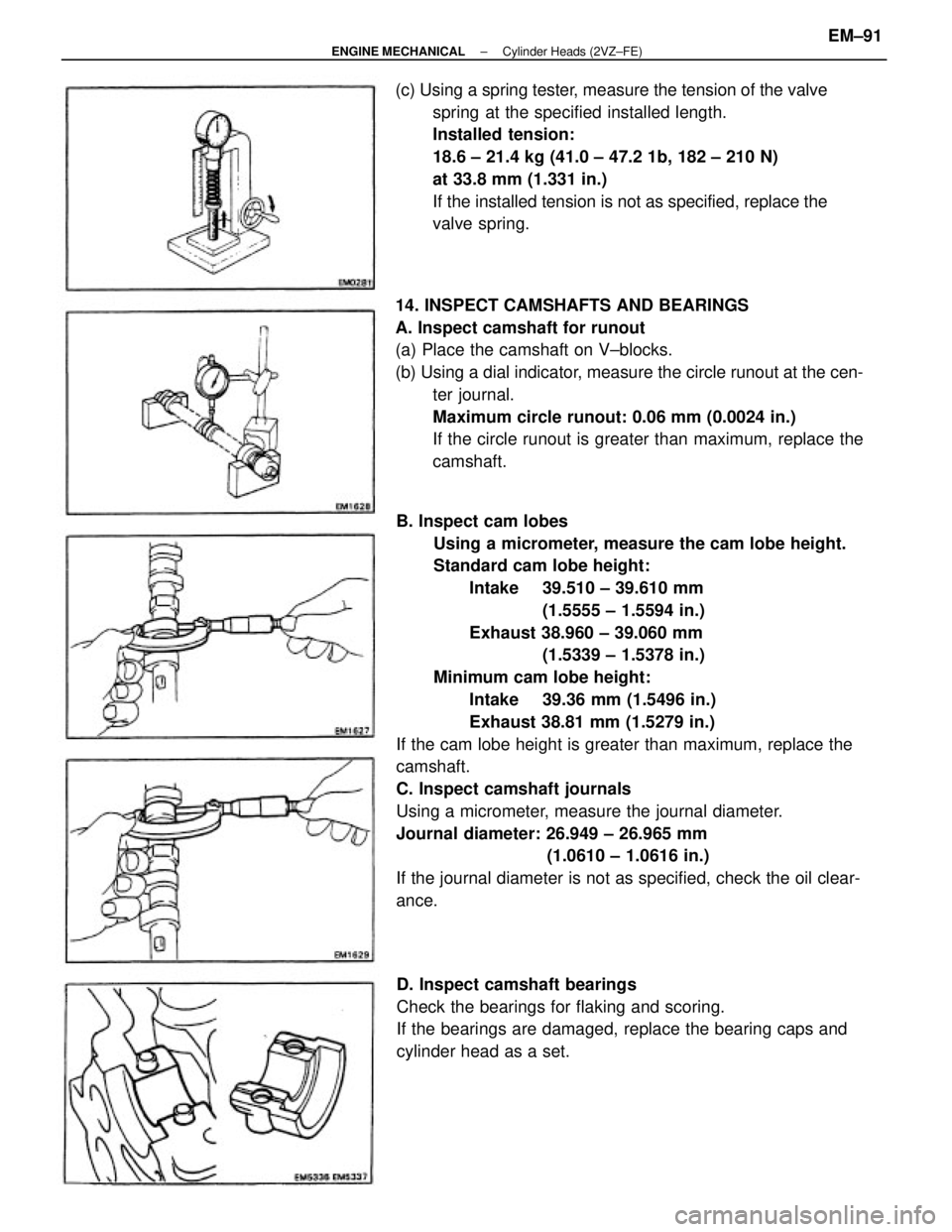
B. Inspect cam lobes
Using a micrometer, measure the cam lobe height.
Standard cam lobe height:
Intake 39.510 ± 39.610 mm
(1.5555 ± 1.5594 in.)
Exhaust 38.960 ± 39.060 mm
(1.5339 ± 1.5378 in.)
Minimum cam lobe height:
Intake 39.36 mm (1.5496 in.)
Exhaust 38.81 mm (1.5279 in.)
If the cam lobe height is greater than maximum, replace the
camshaft.
C. Inspect camshaft journals
Using a micrometer, measure the journal diameter.
Journal diameter: 26.949 ± 26.965 mm
(1.0610 ± 1.0616 in.)
If the journal diameter is not as specified, check the oil clear-
ance. 14. INSPECT CAMSHAFTS AND BEARINGS
A. Inspect camshaft for runout
(a) Place the camshaft on V±blocks.
(b) Using a dial indicator, measure the circle runout at the cen-
ter journal.
Maximum circle runout: 0.06 mm (0.0024 in.)
If the circle runout is greater than maximum, replace the
camshaft. (c) Using a spring tester, measure the tension of the valve
spring at the specified installed length.
Installed tension:
18.6 ± 21.4 kg (41.0 ± 47.2 1b, 182 ± 210 N)
at 33.8 mm (1.331 in.)
If the installed tension is not as specified, replace the
valve spring.
D. Inspect camshaft bearings
Check the bearings for flaking and scoring.
If the bearings are damaged, replace the bearing caps and
cylinder head as a set.
± ENGINE MECHANICALCylinder Heads (2VZ±FE)EM±91
Page 1362 of 2389
HINT:
wCaster changes 30' with each spacer.
wDo not install more than two spacers.
8. INSPECT TOE±IN
Measure toe±in with a toe±in gauge in the following
procedure.
(a) Bounce the vehicle up and down to stabilize the sus-
pension.
(b) Move the vehicle forward about 5 m (16.4 ft ) with the
front wheel in the straight±ahead position on a level
place.
(c) Mark the center of each rear tread and measure the
distance between the marks of the right and left tires.
(e) Measure the distance between the marks on the
front of the tires.
Inspection standard: 1
+ 2 mm (0.04 + 0.08 in.)
If necessary, adjust the toe±in.(d) Advance the vehicle until the marks on the rear
sides of the tires come to the measuring heights
of the gauge on the front side.
HINT: If the tire rolls too far, repeat from step (b).
9. ADJUST TOE±!N
(a) Remove the boot clips.
(b) Loosen the tie rod end lock nut.
± FRONT AXLE AND SUSPENSIONFront Wheel AlignmentFA ± 5
Page 1413 of 2389
Ball Joints
INSPECTION OF BALL JOINTS
1. INSPECT BALL JOINTS FOR EXCESSIVE LOOSENESS
(a) Jack up the front of the vehicle and place a wooden
block with the height of 180 ± 200 mm (7.09 ± 7.87
in.) under one front tire.
(b) Lower the jack until there is about half a load on one
front of coil spring. Place stands under the vehicle
for safety.
(e) Make sure the front wheels are in a straight forward
position and block the wheel with chocks.
(d) Move the lower arm up and down and check that the
ball joint has no excessive play.
Ball joint vertical play: 0 mm (0 in.)
FRONT SUSPENSION
COMPONENTS
± FRONT AXLE AND SUSPENSIONFront SuspensionFA±56
Page 1921 of 2389

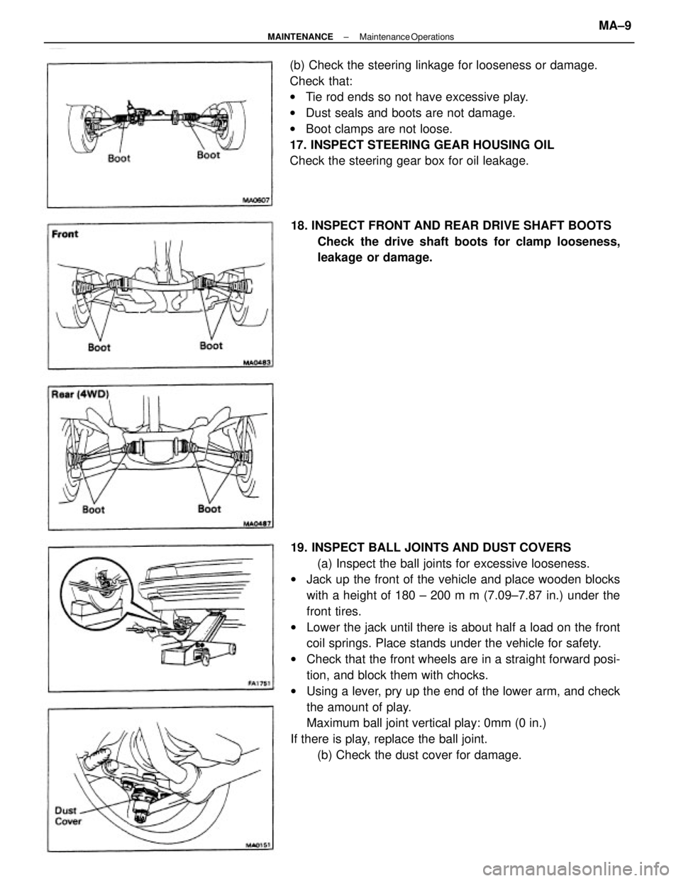
19. INSPECT BALL JOINTS AND DUST COVERS
(a) Inspect the ball joints for excessive looseness.
wJack up the front of the vehicle and place wooden blocks
with a height of 180 ± 200 m m (7.09±7.87 in.) under the
front tires.
wLower the jack until there is about half a load on the front
coil springs. Place stands under the vehicle for safety.
wCheck that the front wheels are in a straight forward posi-
tion, and block them with chocks.
wUsing a lever, pry up the end of the lower arm, and check
the amount of play.
Maximum ball joint vertical play: 0mm (0 in.)
If there is play, replace the ball joint.
(b) Check the dust cover for damage. (b) Check the steering linkage for looseness or damage.
Check that:
wTie rod ends so not have excessive play.
wDust seals and boots are not damage.
wBoot clamps are not loose.
17. INSPECT STEERING GEAR HOUSING OIL
Check the steering gear box for oil leakage.
18. INSPECT FRONT AND REAR DRIVE SHAFT BOOTS
Check the drive shaft boots for clamp looseness,
leakage or damage.
± MAINTENANCEMaintenance OperationsMA±9
Page 2089 of 2389

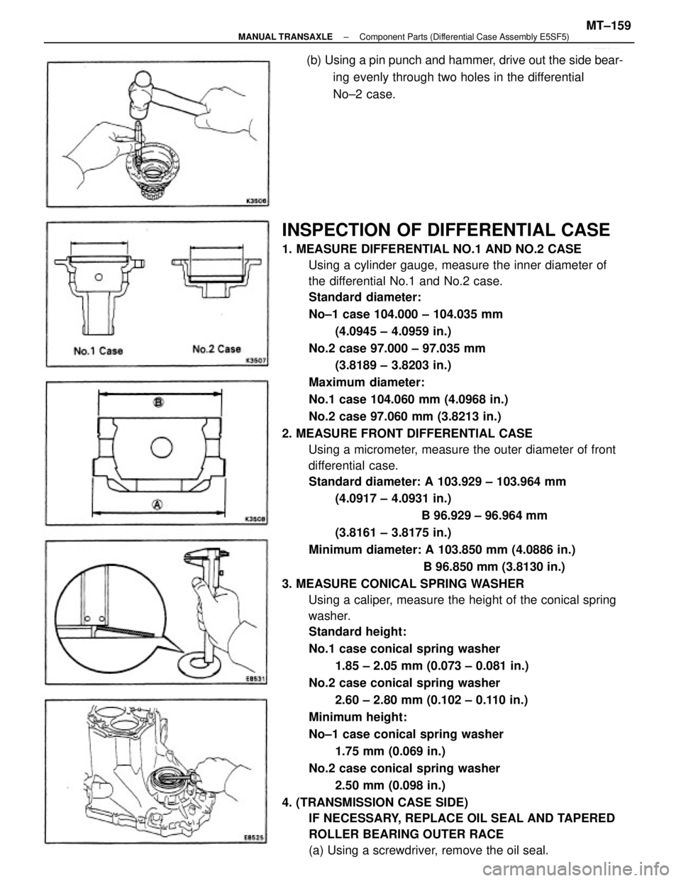
INSPECTION OF DIFFERENTIAL CASE
1. MEASURE DIFFERENTIAL NO.1 AND NO.2 CASE
Using a cylinder gauge, measure the inner diameter of
the differential No.1 and No.2 case.
Standard diameter:
No±1 case 104.000 ± 104.035 mm
(4.0945 ± 4.0959 in.)
No.2 case 97.000 ± 97.035 mm
(3.8189 ± 3.8203 in.)
Maximum diameter:
No.1 case 104.060 mm (4.0968 in.)
No.2 case 97.060 mm (3.8213 in.)
2. MEASURE FRONT DIFFERENTIAL CASE
Using a micrometer, measure the outer diameter of front
differential case.
Standard diameter: A 103.929 ± 103.964 mm
(4.0917 ± 4.0931 in.)
B 96.929 ± 96.964 mm
(3.8161 ± 3.8175 in.)
Minimum diameter: A 103.850 mm (4.0886 in.)
B 96.850 mm (3.8130 in.)
3. MEASURE CONICAL SPRING WASHER
Using a caliper, measure the height of the conical spring
washer.
Standard height:
No.1 case conical spring washer
1.85 ± 2.05 mm (0.073 ± 0.081 in.)
No.2 case conical spring washer
2.60 ± 2.80 mm (0.102 ± 0.110 in.)
Minimum height:
No±1 case conical spring washer
1.75 mm (0.069 in.)
No.2 case conical spring washer
2.50 mm (0.098 in.)
4. (TRANSMISSION CASE SIDE)
IF NECESSARY, REPLACE OIL SEAL AND TAPERED
ROLLER BEARING OUTER RACE
(a) Using a screwdriver, remove the oil seal. (b) Using a pin punch and hammer, drive out the side bear-
ing evenly through two holes in the differential
No±2 case.
± MANUAL TRANSAXLEComponent Parts (Differential Case Assembly E5SF5)MT±159
Page 2119 of 2389
(b) Coat the lip of oil seal with MP grease.
(c) Using a socket wrench and hammer, drive in a
new oil seal as shown.
Oil seal height: 7.5 ± 8.5 mm (0.295 ± 0.335
in.) 16. IF NECESSARY, REPLACE SHIFT FORK
SHAFT OIL SEAL
(a) Using a screwdriver and hammer, remove the oil seal.
17. IF NECESSARY, REPLACE SIDE GEAR SHAFT HOLDER
BEARING
(a) Using snap ring pliers, remove the snap ring.
(c) Using SST and a press, install a new bearing as
shown.
SST 09316±60010 (09316±00010) (b) Using a press, remove the bearing from the
side gear shaft holder.
± MANUAL TRANSAXLEComponent Parts (Transfer Assembly E56F5)MT±174