1986 TOYOTA CAMRY V20 height
[x] Cancel search: heightPage 708 of 2389

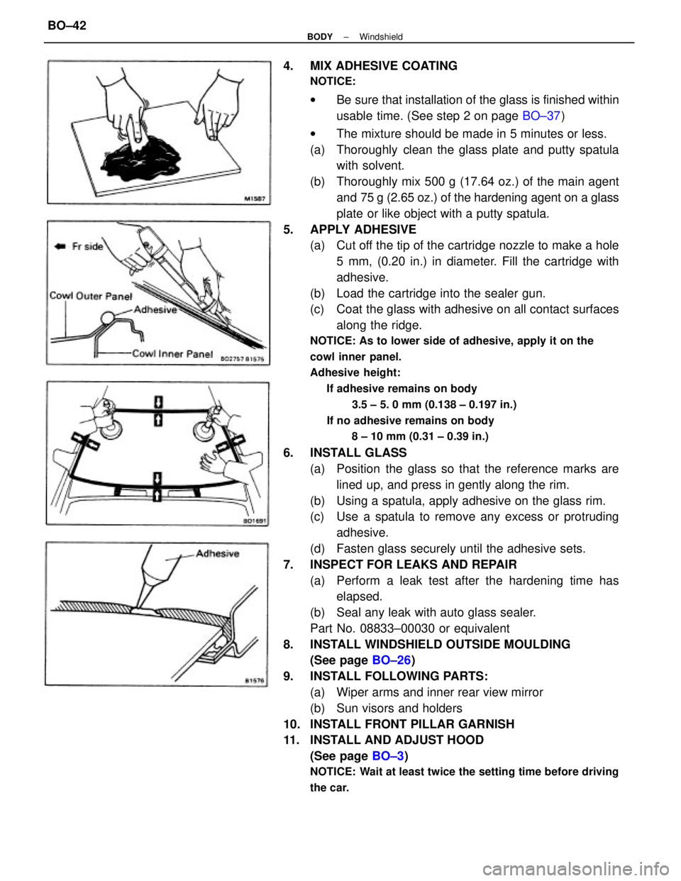
4. MIX ADHESIVE COATING
NOTICE:
wBe sure that installation of the glass is finished within
usable time. (See step 2 on page BO±37)
wThe mixture should be made in 5 minutes or less.
(a) Thoroughly clean the glass plate and putty spatula
with solvent.
(b) Thoroughly mix 500 g (17.64 oz.) of the main agent
and 75 g (2.65 oz.) of the hardening agent on a glass
plate or like object with a putty spatula.
5. APPLY ADHESIVE
(a) Cut off the tip of the cartridge nozzle to make a hole
5 mm, (0.20 in.) in diameter. Fill the cartridge with
adhesive.
(b) Load the cartridge into the sealer gun.
(c) Coat the glass with adhesive on all contact surfaces
along the ridge.
NOTICE: As to lower side of adhesive, apply it on the
cowl inner panel.
Adhesive height:
If adhesive remains on body
3.5 ± 5. 0 mm (0.138 ± 0.197 in.)
If no adhesive remains on body
8 ± 10 mm (0.31 ± 0.39 in.)
6. INSTALL GLASS
(a) Position the glass so that the reference marks are
lined up, and press in gently along the rim.
(b) Using a spatula, apply adhesive on the glass rim.
(c) Use a spatula to remove any excess or protruding
adhesive.
(d) Fasten glass securely until the adhesive sets.
7. INSPECT FOR LEAKS AND REPAIR
(a) Perform a leak test after the hardening time has
elapsed.
(b) Seal any leak with auto glass sealer.
Part No. 08833±00030 or equivalent
8. INSTALL WINDSHIELD OUTSIDE MOULDING
(See page BO±26)
9. INSTALL FOLLOWING PARTS:
(a) Wiper arms and inner rear view mirror
(b) Sun visors and holders
10. INSTALL FRONT PILLAR GARNISH
11. INSTALL AND ADJUST HOOD
(See page BO±3)
NOTICE: Wait at least twice the setting time before driving
the car.
± BODYWindshieldBO±42
Page 741 of 2389

BODY DIMENSIONS
General Information
1. BASIC DIMENSIONS
(a) There are two types of dimensions in the diagram.
wStraight±line distance between the center of two
measuring points.
HINT:
1. The height of the left and right pointers must be equal.
2. Always calibrate the tracking gauge before measuring
or after adjusting the pointer height.
3. Take care not to drop the tracking gauge or otherwise
shock it.
4. Confirm that the pointers are securely in the holes. 2. MEASURING
(a) Basically, all measurements are to be done with a
tracking gauge. For portion where it is not possible to
use a tracking gauge, a tape measure should be
used.
(b) Use only a tracking gauge that has no looseness in
the body, measuring plate, or pointers. wThe height from an imaginary standard line.
(b) In cases i n which only one dimension is given, left
and right are symmetrical.
(c) The dimensions in the following drawing indicate ac-
tual distance. Therefore, please use the dimensions
as a reference.
(e) When using a tape measure, avoid twists and bends
in the tape.
(d) When tracking a diagonal measurement from the front
spring support inner hole to the suspension member
upper rear installation hole, measure along the front
spring support panel surface.
± BODYBody DimensionsBO±75
Page 857 of 2389

CHECKS AND ADJUSTMENTS
CHECK AND ADJUSTMENT OF BRAKE
PEDAL
1. CHECK THAT PEDAL HEIGHT IS CORRECT
Pedal height from asphalt sheet:
177.5 ± 187.5 mm (6.988 ± 7.382 in.)
If incorrect, adjust the pedal height.
2. IF NECESSARY, ADJUST PEDAL HEIGHT
(a) If necessary, remove the instrument lower finish pan-
el and air duct.
(b) Loosen the stop light switch lock nut.
(e) Sufficiently loosen the stop light switch.
(d) Loosen the push rod lock nut.
(e) Adjust the pedal height by turning the pedal push
rod.
(f) Return the stop light switch until it lightly contacts the
pedal stopper.
(g) Tighten the two lock nuts.
(h) Check that the stop lights light when the brake pedal
depressed.
(i) After adjusting the pedal height, check and adjust
the pedal freeplay.
3. CHECK THAT PEDAL FREEPLAY IS CORRECT
(a) Stop the engine and depress the brake pedal sever-
al times until there is no more vacuum left in the
booster.
(b) Push in the pedal until the beginning of resistance
is felt. Measure the distance, as shown.
Pedal freeplay: 3 ±6 mm (0.12 ± 0.24 in.)
HINT: The freeplay to the first resistance is due to the play
between the clevis and pin. And it is 1 3 mm (0.04±
0.12 in.) on the pedal.
4. IF NECESSARY, ADJUST PEDAL FREEPLAY
(a) If incorrect, adjust the pedal freeplay by turning the
pedal push rod.
(b) Start the engine and confirm that pedal freepiay ex-
ists.
(e) After adjusting the pedal freeplay, check the pedal
height.
(d) Install the air duct and instrument lower finish panel.
± BRAKE SYSTEMChecks and AdjustmentsBR±6
Page 933 of 2389

Deceleration Sensor Operation
Diagnosis System (For 4WD)
PRECAUTION
While checking the deceleration sensor diagnosis
system, A.B.S. does not work and brake system works as
normal brake system.
INSPECTION OF DIAGNOSIS SYSTEM
1. INSPECT BATTERY VOLTAGE
Inspect that the battery voltage is about 12 V.
2. CHECK THAT WARNING LIGHT TURNS ON
(a) Turn the ignition switch on.
(b) Check that the ºANTILOCKº warning light turns on for
3 seconds.
If not, inspect and repair or replace the fuse, bulb and wire
harness.
(e) Check that the ºANTILOCKº warning light turns off.
(d) Turn the ignition switch off.
3. PERFORM FOLLOWING STEPS
(a) Remove the rubber cap from the Ts connector lo-
cated in front of the actuator.
(b) Connect the terminals of Ts connector.
(c) Pull the parking brake lever up and depress the brake
pedal, and start the engine.
4. INSPECT SENSOR DETECTION POINT
(a) Jack up the rear side of the vehicle slowly as shown.
HINT: When measuring the height, measure at the center
of the rear bumper lower edge.
(b) Check that the warning light does not turn on.
(c) Jack down the vehicle and check that the warning
light blinking. (d) Check that the warning light blinks about 1 time every
1 second as shown.
If the warning light does not blink, inspect the parking brake
switch, stop light switch, Ts connector, deceleration sensor
installation and computer.
± BRAKE SYSTEMAnti±lock Brake System (A.B.S.)BR±82
Page 934 of 2389

(d) Jack up the front side of the vehicle slowly as shown.
HINT: When measuring the height, measure at the center
of the lower body or spoiler edge of the vehicle.
(e) Check that the warning light does not turn on.
(f) Jack down the vehicle and check that the warning
light blinking.
If the warning light turns on, inspect the deceleration se
sor installation. And if the sensor installation is ±OK, r
place the deceleration sensor.
(e) Drive the vehicle straight ahead at about 20 km/h
(12.4 mph) or more, depress the brake pedal strong±
ly.
(f) Check that the warning light light pattern changes af-
ter braking as shown.
If the operation is not as specified, inspect the deceleration
sensor installation. And if the sensor installation is OK, r
place the deceleration sensor. 5. INSPECT SENSOR OPERATION
(a) Drive the vehicle straight ahead at about 10 km/h l6.2
mph) or more, lightly depress the brake pedal.
(b) Check that there is no change in the warning light
light pattern.
(c) Drive the vehicle straight ahead at about 20 km/h
(12.4 mph) or more, depress the brake pedal a little
strong.
(d) Check that the warning light turns on while braking.
6. REMOVE SHORT PIN
(a) Stop the engine.
(b) Remove the short pin or wire from the Ts connector.
(c) Install the rubber cap to the Ts connector.
± BRAKE SYSTEMAnti±lock Brake System (A.B.S.)BR±83
Page 976 of 2389

CHECK AND ADJUSTMENT OF
CLUTCH PEDAL
1. CHECK THAT PEDAL HEIGHT IS CORRECT
Pedal height from asphalt shaft 181 ± 191 mm
(7:13 ± 7.52 in.)
2. IF NECESSARY, ADJUST PEDAL HEIGHT
(a) Remove the instrument lower finish panel and discon-
nect the air duct.
(b) Loosen the lock nut and turn the stopper bolt (w/o
Cruise control system) or clutch switch (w/ Cruise
control system) until the height is correct. Tighten the
lock nut.
HINT: Before rotating the clutch switch for pedal height
adjustment, disconnect the clutch switch connector.
3. CHECK THAT PEDAL FREEPLAY AND PUSH ROD
PLAY ARE CORRECT
(Pedal Freeplay)
Push in the pedal until the beginning of clutch resistance
is felt.
Pedal freeplay: 5 ± 15 mm (0.20 ± 0.59 in.)
Push rod play at pedal top: 1.0 ± 5.0 mm
(0.039 ± 0.197 in.)
4. IF NECESSARY, ADJUST PEDAL FREEPLAY AND
PUSH ROD PLAY
(a) Loosen the lock nut and turn the push rod until the free-
play and push rod play are correct.
(b) Tighten the lock nut.
(e) After adjusting the pedal freeplay, check the pedal
height.
(d) Connect the air duct and install the lower finish panel.
5. INSPECT CLUTCH RELEASE POINT
(a) Pull the parking brake lever and install wheel stopper.
(b) Start the engine and idle the engine.
(e) Without depressing the clutch pedal, slowly shift the
shift lever into reverse position until the gears contact.
(d) Gradually depress the clutch pedal and measure the
stroke distance from the point the gear noise stops
(release point) up to the full stroke end position.
Standard distance: 25 mm (0.98 in.) or more
(From pedal stroke end position to release point)
If the distance is not as specified, perform the following
operation.
wInspect pedal height.
wInspect push rod play and pedal free play.
wBleed the clutch line.
wInspect the clutch cover and disc.
± CLUTCHCheck and Adjustment of Clutch PedalCL±3
Page 977 of 2389

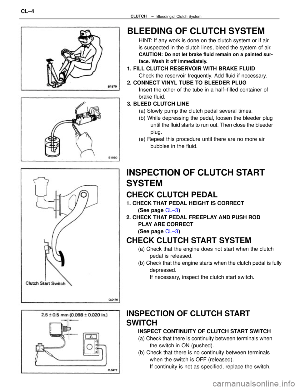
BLEEDING OF CLUTCH SYSTEM
HINT: If any work is done on the clutch system or if air
is suspected in the clutch lines, bleed the system of air.
CAUTION: Do not let brake fluid remain on a painted sur-
face. Wash it off immediately.
1. FILL CLUTCH RESERVOIR WITH BRAKE FLUID
Check the reservoir frequently. Add fluid if necessary.
2. CONNECT VINYL TUBE TO BLEEDER PLUG
Insert the other of the tube in a half±filled container of
brake fluid.
3. BLEED CLUTCH LINE
(a) Slowly pump the clutch pedal several times.
(b) While depressing the pedal, loosen the bleeder plug
until the fluid starts to run out. Then close the bleeder
plug.
(e) Repeat this procedure until there are no more air
bubbles in the fluid.
INSPECTION OF CLUTCH START
SYSTEM
CHECK CLUTCH PEDAL
1. CHECK THAT PEDAL HEIGHT IS CORRECT
(See page CL±3)
2. CHECK THAT PEDAL FREEPLAY AND PUSH ROD
PLAY ARE CORRECT
(See page CL±3)
CHECK CLUTCH START SYSTEM
(a) Check that the engine does not start when the clutch
pedal is released.
(b) Check that the engine starts when the clutch pedal is fully
depressed.
If necessary, inspect the clutch start switch.
INSPECTION OF CLUTCH START
SWITCH
INSPECT CONTINUITY OF CLUTCH START SWITCH
(a) Check that there is continuity between terminals when
the switch in ON (pushed).
(b) Check that there is no continuity between terminals
when the switch is OFF (released).
If continuity is not as specified, replace the switch.
± CLUTCH
Bleeding of Clutch SystemCL±4
Page 978 of 2389

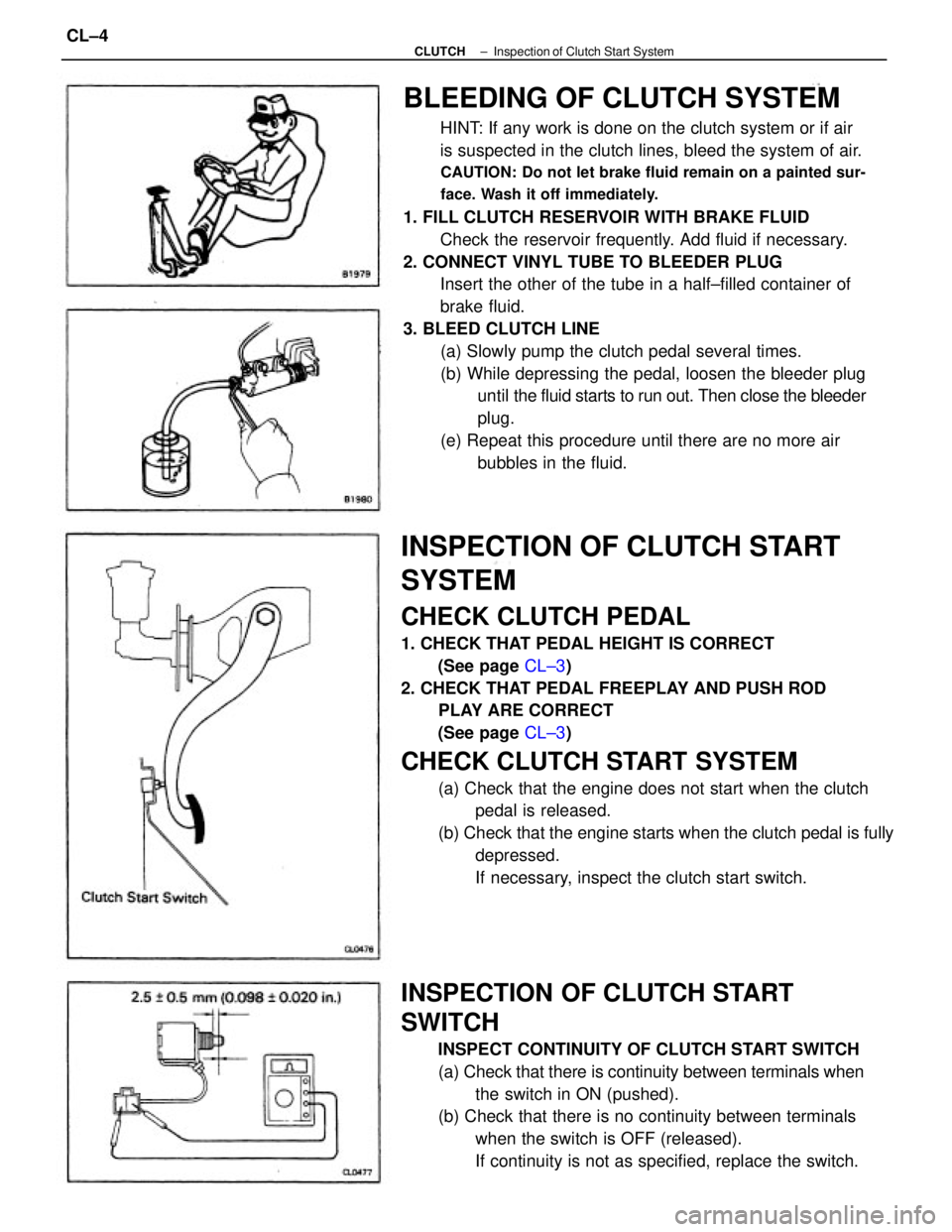
BLEEDING OF CLUTCH SYSTEM
HINT: If any work is done on the clutch system or if air
is suspected in the clutch lines, bleed the system of air.
CAUTION: Do not let brake fluid remain on a painted sur-
face. Wash it off immediately.
1. FILL CLUTCH RESERVOIR WITH BRAKE FLUID
Check the reservoir frequently. Add fluid if necessary.
2. CONNECT VINYL TUBE TO BLEEDER PLUG
Insert the other of the tube in a half±filled container of
brake fluid.
3. BLEED CLUTCH LINE
(a) Slowly pump the clutch pedal several times.
(b) While depressing the pedal, loosen the bleeder plug
until the fluid starts to run out. Then close the bleeder
plug.
(e) Repeat this procedure until there are no more air
bubbles in the fluid.
INSPECTION OF CLUTCH START
SYSTEM
CHECK CLUTCH PEDAL
1. CHECK THAT PEDAL HEIGHT IS CORRECT
(See page CL±3)
2. CHECK THAT PEDAL FREEPLAY AND PUSH ROD
PLAY ARE CORRECT
(See page CL±3)
CHECK CLUTCH START SYSTEM
(a) Check that the engine does not start when the clutch
pedal is released.
(b) Check that the engine starts when the clutch pedal is fully
depressed.
If necessary, inspect the clutch start switch.
INSPECTION OF CLUTCH START
SWITCH
INSPECT CONTINUITY OF CLUTCH START SWITCH
(a) Check that there is continuity between terminals when
the switch in ON (pushed).
(b) Check that there is no continuity between terminals
when the switch is OFF (released).
If continuity is not as specified, replace the switch.
± CLUTCHInspection of Clutch Start SystemCL±4