Page 1142 of 2389
(b) Apply battery voltage across the terminals
(c) Check that air flows from pipe E to filter.
If operation is not as specified, replace the VSV. C. Inspect VSV operation
(a) Check that air flow from pipes E to G.
± EFI SYSTEMElectronic Control System (Fuel Pressure Control System))FI±128
Page 1158 of 2389
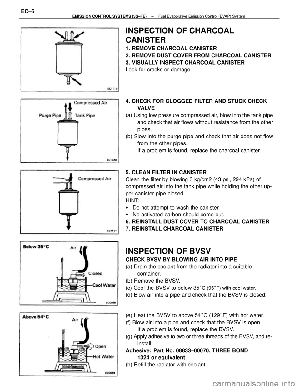
5. CLEAN FILTER IN CANISTER
Clean the filter by blowing 3 kg/cm2 (43 psi, 294 kPa) of
compressed air into the tank pipe while holding the other up-
per canister pipe closed.
HINT:
wDo not attempt to wash the canister.
wNo activated carbon should come out.
6. REINSTALL DUST COVER TO CHARCOAL CANISTER
7. REINSTALL CHARCOAL CANISTER
INSPECTION OF BVSV
CHECK BVSV BY BLOWING AIR INTO PIPE
(a) Drain the coolant from the radiator into a suitable
container.
(b) Remove the BVSV.
(c) Cool the BVSV to below 35
°C (95°F) with cool water.
(d) Blow air into a pipe and check that the BVSV is closed. 4. CHECK FOR CLOGGED FILTER AND STUCK CHECK
VA LV E
(a) Using low pressure compressed air, blow into the tank pipe
and check that air flows without resistance from the other
pipes.
(b) Slow into the purge pipe and check that air does not flow
from the other pipes.
If a problem is found, replace the charcoal canister.
(e) Heat the BVSV to above 54°C (129°F) with hot water.
(f) Blow air into a pipe and check that the BVSV is open.
If a problem is found, replace the BVSV.
(g) Apply adhesive to two or three threads of the BVSV, and re-
install.
Adhesive: Part No. 08833±00070, THREE BOND
1324 or equivalent
(h) Refill the radiator with coolant.
INSPECTION OF CHARCOAL
CANISTER
1. REMOVE CHARCOAL CANISTER
2. REMOVE DUST COVER FROM CHARCOAL CANISTER
3. VISUALLY INSPECT CHARCOAL CANISTER
Look for cracks or damage.
± EMISSION CONTROL SYSTEMS (3S±FE)Fuel Evaporative Emission Control (EVAP) SystemEC±6
Page 1170 of 2389
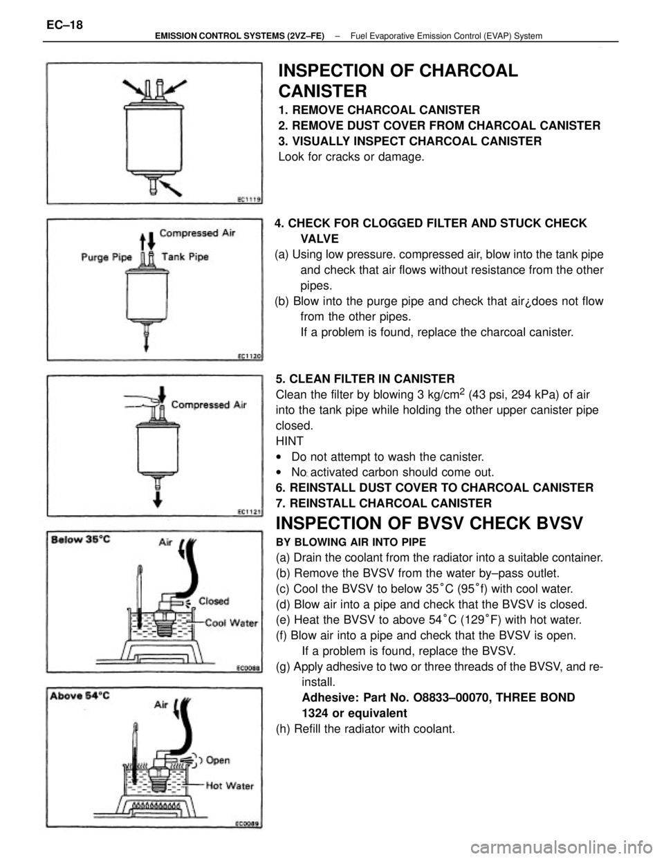
5. CLEAN FILTER IN CANISTER
Clean the filter by blowing 3 kg/cm
2 (43 psi, 294 kPa) of air
into the tank pipe while holding the other upper canister pipe
closed.
HINT
wDo not attempt to wash the canister.
wNo activated carbon should come out.
6. REINSTALL DUST COVER TO CHARCOAL CANISTER
7. REINSTALL CHARCOAL CANISTER
INSPECTION OF BVSV CHECK BVSV
BY BLOWING AIR INTO PIPE
(a) Drain the coolant from the radiator into a suitable container.
(b) Remove the BVSV from the water by±pass outlet.
(c) Cool the BVSV to below 35°C (95°f) with cool water.
(d) Blow air into a pipe and check that the BVSV is closed.
(e) Heat the BVSV to above 54°C (129°F) with hot water.
(f) Blow air into a pipe and check that the BVSV is open.
If a problem is found, replace the BVSV.
(g) Apply adhesive to two or three threads of the BVSV, and re-
install.
Adhesive: Part No. O8833±00070, THREE BOND
1324 or equivalent
(h) Refill the radiator with coolant.
INSPECTION OF CHARCOAL
CANISTER
1. REMOVE CHARCOAL CANISTER
2. REMOVE DUST COVER FROM CHARCOAL CANISTER
3. VISUALLY INSPECT CHARCOAL CANISTER
Look for cracks or damage.
4. CHECK FOR CLOGGED FILTER AND STUCK CHECK
VA LV E
(a) Using low pressure. compressed air, blow into the tank pipe
and check that air flows without resistance from the other
pipes.
(b) Blow into the purge pipe and check that air¿does not flow
from the other pipes.
If a problem is found, replace the charcoal canister.
± EMISSION CONTROL SYSTEMS (2VZ±FE)Fuel Evaporative Emission Control (EVAP) SystemEC±18
Page 1183 of 2389
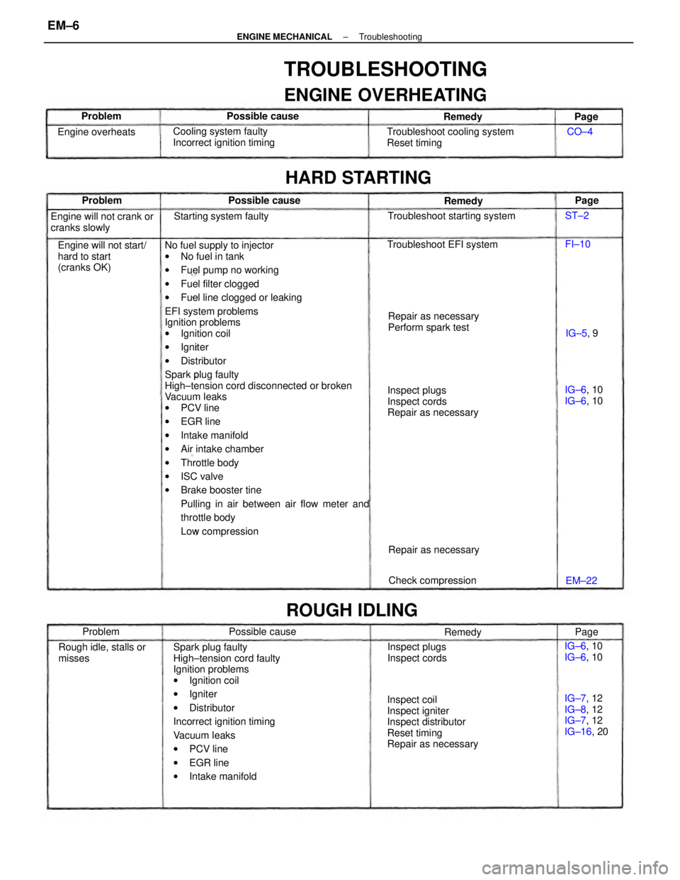
No fuel supply to injector
wNo fuel in tank
wFuel pump no working
wFuel filter clogged
wFuel line clogged or leaking
EFI system problems
Ignition problems
wIgnition coil
wIgniter
wDistributor
Spark plug faulty
High±tension cord disconnected or broken
Vacuum leaks
wPCV line
wEGR line
wIntake manifold
wAir intake chamber
wThrottle body
wISC valve
wBrake booster tine
Pulling in air between air flow meter and
throttle body
Low compression
Spark plug faulty
High±tension cord faulty
Ignition problems
wIgnition coil
wIgniter
wDistributor
Incorrect ignition timing
Vacuum leaks
wPCV line
wEGR line
wIntake manifold
TROUBLESHOOTING
ENGINE OVERHEATING
Inspect coil
Inspect igniter
Inspect distributor
Reset timing
Repair as necessaryInspect plugs
Inspect cords
Repair as necessary Troubleshoot cooling system
Reset timing
Engine will not start/
hard to start
(cranks OK)Cooling system faulty
Incorrect ignition timing
Repair as necessary
Perform spark test Engine will not crank or
cranks slowly
IG±7, 12
IG±8, 12
IG±7, 12
IG±16, 20 Rough idle, stalls or
misses
HARD STARTING
Troubleshoot starting system
Inspect plugs
Inspect cords Troubleshoot EFI system
ROUGH IDLING
Starting system faulty
Check compression Repair as necessary Engine overheats
IG±6, 10
IG±6, 10 IG±6, 10
IG±6, 10 Possible cause
Possible cause Possible cause
Remedy Remedy
Problem
Remedy Problem Problem
IG±5, 9
EM±22Page
Page
Page CO±4
FI±10 ST±2
± ENGINE MECHANICALTroubleshootingEM±6
Page 1198 of 2389
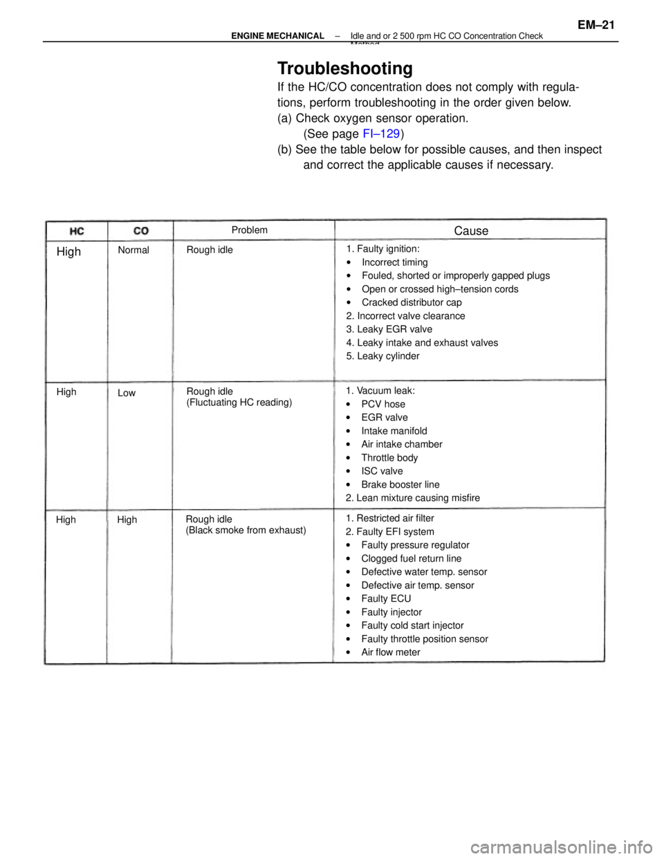
Troubleshooting
If the HC/CO concentration does not comply with regula-
tions, perform troubleshooting in the order given below.
(a) Check oxygen sensor operation.
(See page FI±129)
(b) See the table below for possible causes, and then inspect
and correct the applicable causes if necessary.
1. Faulty ignition:
wIncorrect timing
wFouled, shorted or improperly gapped plugs
wOpen or crossed high±tension cords
wCracked distributor cap
2. Incorrect valve clearance
3. Leaky EGR valve
4. Leaky intake and exhaust valves
5. Leaky cylinder
1. Restricted air filter
2. Faulty EFI system
wFaulty pressure regulator
wClogged fuel return line
wDefective water temp. sensor
wDefective air temp. sensor
wFaulty ECU
wFaulty injector
wFaulty cold start injector
wFaulty throttle position sensor
wAir flow meter 1. Vacuum leak:
wPCV hose
wEGR valve
wIntake manifold
wAir intake chamber
wThrottle body
wISC valve
wBrake booster line
2. Lean mixture causing misfire
Rough idle
(Black smoke from exhaust)Rough idle
(Fluctuating HC reading) Rough idleProblem
Normal
Cause
High
High
HighHigh
Low
± ENGINE MECHANICALIdle and or 2 500 rpm HC CO Concentration CheckMethod
EM±21
Page 1861 of 2389
PRECAUTIONS FOR VEHICLES EQUIPPED WITH A
CATALYTIC CONVERTER
CAUTION: If large amounts of unburned gasoline flow into the converter, it may overheat
and create a fire hazard. To prevent this, observe the following precautions and
explain them to your customer.
1. Use only unleaded gasoline.
2. Avoid prolonged idling.
Avoid running the engine at idle speed for more than 20
minutes.
3. Avoid spark jump test.
(a) Spark jump test only when absolutely necessary. Perform this test as rapidly as pos-
sible.
(b) While testing, never race the engine.
4. Avoid prolonged engine compression measurement.
Engine compression tests must be made as rapidly as possible.
5. Do not run engine when fuel tank is nearly empty.
This may cause the engine to misfire and create an extra
load on the converter.
6. Avoid coasting with ignition turned off and prolonged braking.
7. Do not dispose of used catalyst along with parts contaminated with gasoline or oil.(f) When steam cleaning an engine, protect the distribu-
tor, air filter and VCV from water.
(g) Never use an impact wrench to remove or install tem-
perature switches or temperature sensors.
(h) When checking continuity at the wire connector, insert
the tester probe carefully to prevent terminals from
bending.
(i) When using a vacuum gauge, never force the hose
onto a connector that is too large. Use a step±down
adapter instead. Once the hose has been stretched,
it may leak.
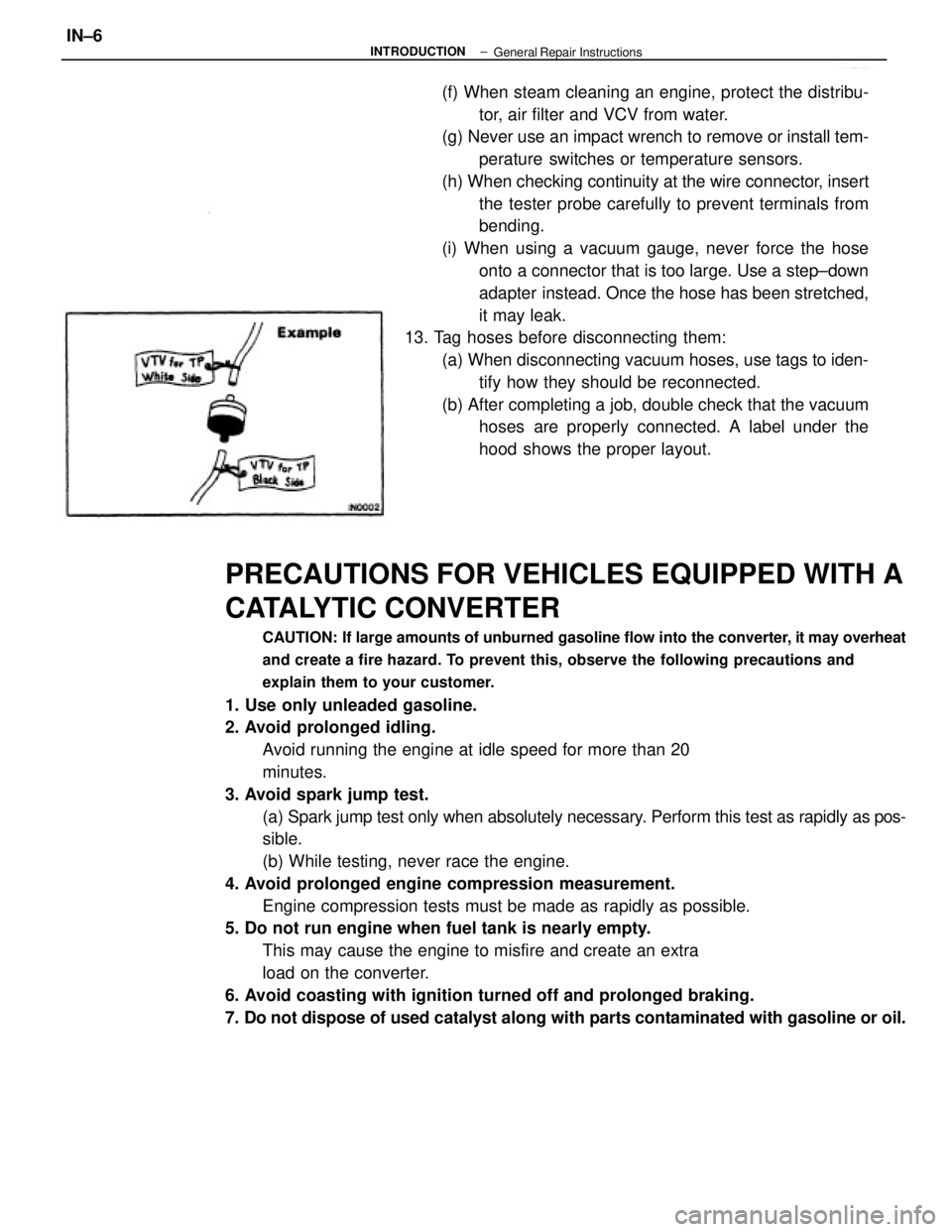
13. Tag hoses before disconnecting them:
(a) When disconnecting vacuum hoses, use tags to iden-
tify how they should be reconnected.
(b) After completing a job, double check that the vacuum
hoses are properly connected. A label under the
hood shows the proper layout.
± INTRODUCTIONIN±6General Repair Instructions
Page 1862 of 2389
PRECAUTIONS FOR VEHICLES EQUIPPED WITH A
CATALYTIC CONVERTER
CAUTION: If large amounts of unburned gasoline flow into the converter, it may overheat
and create a fire hazard. To prevent this, observe the following precautions and
explain them to your customer.
1. Use only unleaded gasoline.
2. Avoid prolonged idling.
Avoid running the engine at idle speed for more than 20
minutes.
3. Avoid spark jump test.
(a) Spark jump test only when absolutely necessary. Perform this test as rapidly as pos-
sible.
(b) While testing, never race the engine.
4. Avoid prolonged engine compression measurement.
Engine compression tests must be made as rapidly as possible.
5. Do not run engine when fuel tank is nearly empty.
This may cause the engine to misfire and create an extra
load on the converter.
6. Avoid coasting with ignition turned off and prolonged braking.
7. Do not dispose of used catalyst along with parts contaminated with gasoline or oil.(f) When steam cleaning an engine, protect the distribu-
tor, air filter and VCV from water.
(g) Never use an impact wrench to remove or install tem-
perature switches or temperature sensors.
(h) When checking continuity at the wire connector, insert
the tester probe carefully to prevent terminals from
bending.
(i) When using a vacuum gauge, never force the hose
onto a connector that is too large. Use a step±down
adapter instead. Once the hose has been stretched,
it may leak.
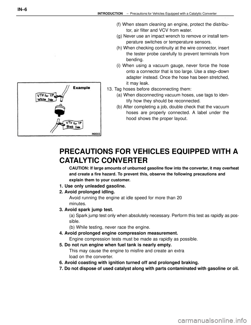
13. Tag hoses before disconnecting them:
(a) When disconnecting vacuum hoses, use tags to iden-
tify how they should be reconnected.
(b) After completing a job, double check that the vacuum
hoses are properly connected. A label under the
hood shows the proper layout.
± INTRODUCTIONPrecautions for Vehicles Equipped with a Catalytic ConverterIN±6
Page 1893 of 2389
3. FILL WITH ENGINE OIL
(a) Clean and install the oil drain plug with a new gasket.
Torque: 2VZ±FE 3S±FE 400 kg±cm (29 ft±lb, 39 N±m)
(b) Fill with new engine oil (API grade SG muitigrade,
fuel±efficient and recommended viscosity oil).
Capacity (3S±FE):
Drain and refill
w/ Oil filter change
4.1 liters (4.3 U S qts, 3.6 Imp. qts)
w/o Oil filter change
3.7 liters (3.9 US qts, 3.3 Imp. qts)
Dry fill 4.5 liters (4.8 U S qts, 4.4 Imp. qts)
Capacity (2VZ±FE):
Drain and refill
w/ Oil filter change
3.9 liters (4.1 US qts, 3.4 Imp. qts)
w/o Oil filter change
3.7 liters (3.9 US qts, 3.3 Imp. qts)
Dry fill 4.6 liters (4.8 US qts, 4.4 Imp. qts)
(c) Install the oil filler cap.
4. START ENGINE AND CHECK FOR LEAKS
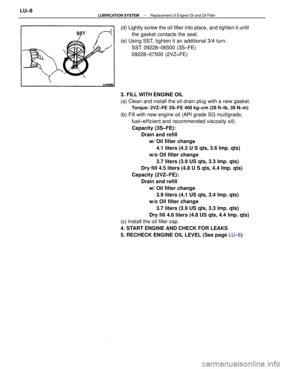
5. RECHECK ENGINE OIL LEVEL (See page LU±6) (d) Lightly screw the oil filter into place, and tighten it until
the gasket contacts the seat.
(e) Using SST, tighten it an additional 3/4 turn.
SST 09228±06500 (3S±FE)
09228±07500 (2VZ=FE)
± LUBRICATION SYSTEMReplacement of Engine Oil and Oil FilterLU±8