Page 1047 of 2389
ON±VEHICLE INSPECTION
1. CHECK FUEL PUMP OPERATION
(a) Turn the ignition switch ON.
NOTICE: Do not start the engine.
(b) Using SST, connect terminals +B and FP of the check con-
nector.
SST 09843±18020
(e) Turn the ignition switch OFF.
If there is no pressure, check the following
parts:
wFusible links
wFuses (ER 15 A, IGN 7.5 A)
wER main relay
wFuel pump
wECU
wWiring connections (e) Check that there is pressure in the hose from the fuel
filter.
HINT: At this time, you will hear fuel return noise.
(d) Remove SST.
SST 09843±18020
± EFI SYSTEMFuel System (Fuel Pump)FI±70
Page 1049 of 2389
(j) Turn the ignition switch ON.
(k) Measure the fuel pressure.
Fuel pressure: 2.7 ± 3.1 kg/cm
2
(38 ± 44 pst, 265 ± 304 kPa)
If pressure is high, replace the fuel pressure regulator.
If pressure is low, check the following parts:
wFuel hoses and connection
wFuel pump
wFuel filter
wFuel pressure regulator
(m) Start the engine. .
(n) Disconnect the vacuum sensing hose from the fuel
pressure regulator, and plug the hose end.
(o) Measure the fuel pressure at idling.
Fuel pressure: 2.7 ± 3.1 kg/cm
2
(38 ± 44 psi, 265 ± 304 kPa) (i) Using SST, connect terminals +B and FP of the check
connector.
SST 09843±18020
(l) Remove SST.
SST 09843±18020
± EFI SYSTEMFuel System (Fuel PumpFI±72
Page 1052 of 2389
4. INSTALL FUEL TANK
When installing the fuel tank, refer to FI±65 for the installation
position of the cushion and the tightening torque.
5. CONNECT CABLE TO NEGATIVE TERMINAL OF
BATTERY 2. INSTALL FUEL PUMP TO FUEL PUMP BRACKET
(a) Connect the fuel hose to the outlet port of the fuel pump.
(b) Connect the wires to the fuel pump with the two nuts.
(e) Push the lower side of the fuel pump, and install the fuel
pump.
3. INSTALL FUEL PUMP BRACKET TO FUEL TANK
(a) Install a new gasket and the pump bracket with the seven
screws.
Torque: 40 kg±cm (35 in.±lb, 3.9 N±m)
(b) Install the bolt of the bracket.
INSTALLATION OF FUEL PUMP
(See page FI±74)
1. INSTALL FUEL PUMP FILTER TO FUEL PUMP
(a) Install the pump filter with a new clip.
(b) Install the rubber cushion.5. REMOVE FUEL PUMP FILTER FROM FUEL PUMP
(a) Remove the rubber cushion.
(b) Using a small screwdriver, remove the clip.
(c) Pull out the pump filter.
± EFI SYSTEMFuel System (Fuel Pump)_FI±75
Page 1054 of 2389
2. INSTALL FUEL PUMP TO FUEL PUMP BRACKET
(a) Connect the fuel hose to the outlet port of the fuel pump.
(b) Connect the wires to the fuel pump with the two nuts.
(c) Push the lower side of the fuel pump, and install the fuel
pump.
4. INSTALL FUEL TANK
When installing the fuel tank, refer to FI±65 for the installation
position of the cushion and the tightening torque.
5. CONNECT CABLE TO NEGATIVE TERMINAL OF
BATTERY INSTALLATION OF FUEL PUMP
(See page FI±76)
1. INSTALL FUEL PUMP FILTER TO FUEL PUMP
(a) Install the pump filter with a new clip.
(b) Install the rubber cushion.
3. INSTALL FUEL PUMP BRACKET TO FUEL TANK
Install a new gasket and the pump bracket with the seven
bolts.
Torque: 30 kg±cm (26 in.±lb, 2.9 N±m)
5. REMOVE FUEL PUMP FILTER FROM FUEL PUMP
(a) Remove the rubber cushion.
(b) Using a small screwdriver, remove the clip.
(e) Pull out the pump filter.
± EFI SYSTEMFuel System (Fuel Pump)FI±77
Page 1103 of 2389

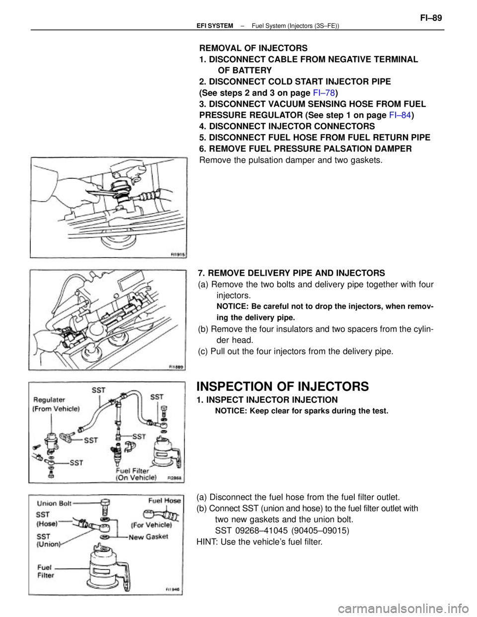
REMOVAL OF INJECTORS
1. DISCONNECT CABLE FROM NEGATIVE TERMINAL
OF BATTERY
2. DISCONNECT COLD START INJECTOR PIPE
(See steps 2 and 3 on page FI±78)
3. DISCONNECT VACUUM SENSING HOSE FROM FUEL
PRESSURE REGULATOR (See step 1 on page FI±84)
4. DISCONNECT INJECTOR CONNECTORS
5. DISCONNECT FUEL HOSE FROM FUEL RETURN PIPE
6. REMOVE FUEL PRESSURE PALSATION DAMPER
Remove the pulsation damper and two gaskets.
7. REMOVE DELIVERY PIPE AND INJECTORS
(a) Remove the two bolts and delivery pipe together with four
injectors.
NOTICE: Be careful not to drop the injectors, when remov-
ing the delivery pipe.
(b) Remove the four insulators and two spacers from the cylin-
der head.
(c) Pull out the four injectors from the delivery pipe.
(a) Disconnect the fuel hose from the fuel filter outlet.
(b) Connect SST (union and hose) to the fuel filter outlet with
two new gaskets and the union bolt.
SST 09268±41045 (90405±09015)
HINT: Use the vehicle's fuel filter.
INSPECTION OF INJECTORS
1. INSPECT INJECTOR INJECTION
NOTICE: Keep clear for sparks during the test.
± EFI SYSTEMFuel System (Injectors (3S±FE))FI±89
Page 1109 of 2389

10. DISCONNECT HOSES AND PARTS
(a) Brake booster vacuum hose
(b) PS vacuum and air hoses
(c) Cruise control vacuum hose
(d) Ground strap connector
(e) Wire harness clamp
Remove the nut, and disconnect the wire harness clamp.
(f) Fuel pressure control VSV hose.
11. DISCONNECT WIRE HARNESS CLAMP
Remove the nut and disconnect the wire harness.
12. DISCONNECT EGR PIPE
13. REMOVE NO.1 ENGINE HANGER AND AIR INTAKE
CHAMBER STAY
(a) Remove the two bolts and No.1 engine hanger.
(b) Remove the bolt, and disconnect the air intake chamber
stay from air intake chamber.
14. REMOVE AIR INTAKE CHAMBER
Remove the two bolts, nuts, air intake chamber and gasket.
15. DISCONNECT CONNECTORS
(a) Cold start injector connector
(b) Water temperature sensor connector
(c) Six injector connectors
16. DISCONNECT WIRE HARNESS CLAMPS FROM LH
DELIVERY PIPE
Disconnect the three wire harness clamp.
17. DISCONNECT FUEL INLET AND TWO RETURN
HOSES
(a) Disconnect the fuel return hoses from the fuel pressure reg-
ulator and No.1 fuel pipe.
(b) Disconnect the fuel inlet hose from the fuel filter.
18. REMOVE NO.2 FUEL PIPE
Remove the two union bolts, four gaskets and No.2 fuel
pipe.
± EFI SYSTEMFuel System (Injectors (2VZ±FE))FI±95
Page 1110 of 2389

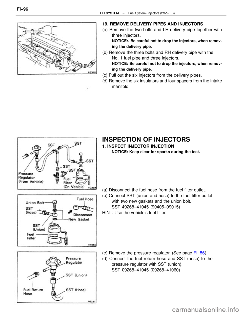
19. REMOVE DELIVERY PIPES AND INJECTORS
(a) Remove the two bolts and LH delivery pipe together with
three injectors.
NOTICE:. Be careful not to drop the injectors, when remov-
ing the delivery pipe.
(b) Remove the three bolts and RH delivery pipe with the
No. 1 fuel pipe and three injectors.
NOTICE: Be careful not to drop the injectors, when remov-
ing the delivery pipe.
(c) Pull out the six injectors from the delivery pipes.
(d) Remove the six insulators and four spacers from the intake
manifold.
(a) Disconnect the fuel hose from the fuel filter outlet.
(b) Connect SST (union and hose) to the fuel fitter outlet
with two new gaskets and the union bolt.
SST 49268±41045 (90405±09015)
HINT: Use the vehicle's fuel filter.
(e) Remove the pressure regulator. (See page FI±86)
(d) Connect the fuel return hose and SST (hose) to the
pressure regulator with SST (union).
SST 09268±41045 (09268±41060)
INSPECTION OF INJECTORS
1. INSPECT INJECTOR INJECTION
NOTICE: Keep clear for sparks during the test.
± EFI SYSTEMFuel System (Injectors (2VZ±FE))FI±96
Page 1113 of 2389

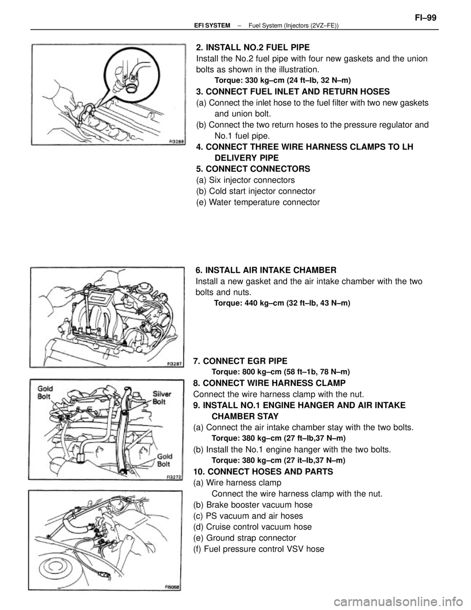
7. CONNECT EGR PIPE
Torque: 800 kg±cm (58 ft±1b, 78 N±m)
8. CONNECT WIRE HARNESS CLAMP
Connect the wire harness clamp with the nut.
9. INSTALL NO.1 ENGINE HANGER AND AIR INTAKE
CHAMBER STAY
(a) Connect the air intake chamber stay with the two bolts.
Torque: 380 kg±cm (27 ft±Ib,37 N±m)
(b) Install the No.1 engine hanger with the two bolts.
Torque: 380 kg±cm (27 it±Ib,37 N±m)
10. CONNECT HOSES AND PARTS
(a) Wire harness clamp
Connect the wire harness clamp with the nut.
(b) Brake booster vacuum hose
(c) PS vacuum and air hoses
(d) Cruise control vacuum hose
(e) Ground strap connector
(f) Fuel pressure control VSV hose2. INSTALL NO.2 FUEL PIPE
Install the No.2 fuel pipe with four new gaskets and the union
bolts as shown in the illustration.
Torque: 330 kg±cm (24 ft±Ib, 32 N±m)
3. CONNECT FUEL INLET AND RETURN HOSES
(a) Connect the inlet hose to the fuel filter with two new gaskets
and union bolt.
(b) Connect the two return hoses to the pressure regulator and
No.1 fuel pipe.
4. CONNECT THREE WIRE HARNESS CLAMPS TO LH
DELIVERY PIPE
5. CONNECT CONNECTORS
(a) Six injector connectors
(b) Cold start injector connector
(e) Water temperature connector
6. INSTALL AIR INTAKE CHAMBER
Install a new gasket and the air intake chamber with the two
bolts and nuts.
Torque: 440 kg±cm (32 ft±lb, 43 N±m)
± EFI SYSTEMFuel System (Injectors (2VZ±FE))FI±99