Page 462 of 2389

MEASURE CENTER DIFFERENTIAL CONTROL PRESSURE (A540H Only)
(a) Warm up the transaxle fluid (122 ± 176°F or 50 ± 80°C)
(b) Measure the line pressure. (See page AT±224)
(e) Remove the transfer case test plug and mount the oil pressure gauge (SST).
SST 09992±00094
(d) Check the parking brake to see that it is fully applied chock the four wheels.
(e) Disconnect the connector from ECT ECU.
(f) Start the engine.
(g) Apply battery voltage to terminal SD1, or SD2 of the wire harness side connector and turn the No. .1
and No. 2 center differential control solenoid valves to either ON or OFF.
(h) Shift into the L range, step down strongly on the brake pedal with your left foot and while manipulating the
accelerator pedal with the right foot, measure the pressure at the engine speeds specified in the table.
kg/cm2 (psi, kPa)
HINT: After inspecting the center differential control pressure, erase the diagnosis codes (No. 73 and 74)
from the memory.
Condition of
Solenoid
ValvesNo. 1 Solenoid
Valve
No. 2 Solenoid
Valve
Engine
RPML range
Range
Idling
Stall
± AUTOMATIC TRANSAXLETroubleshooting (Mechanical System Tests) (A540E and
A540H)AT±226
Page 491 of 2389

COMPONENT PARTS
General Notes
The instructions here are organized so that you work on only one component group at a time.
This will help avoid confusion from similar±looking parts of different subassemblies being on your
workbench at the same time.
The component groups are inspected and repaired from the converter housing side.
As much as possible, complete the inspection, repair and assembly before proceeding to the next
component group. If a component group can not be assembled because parts are being ordered,
be sure to
keep all parts of that group in a separate container while proceeding with disassembly, inspection,
repair and assembly of other component groups.
Recommended fluid for the automatic transaxle: A540E ATF DEXRON�II
A540H ATF Type T or equivalent
Recommended oil for the transfer: Transaxle oil E50, API GL5, SAE 75W±90 or equivalent
GENERAL CLEANING NOTES:
1. All disassembled parts should be washed clean, with any fluid passages and holes blown through with
compressed air.
2. When using compressed air to dry parts, always aim away from yourself to prevent accidentally spraying
automatic transaxle fluid or kerosene in your face.
3. The recommended automatic transaxle fluid or kerosene should be used for cleaning.
PARTS ARRANGEMENT:
1. After cleaning, the parts should be arranged in proper order to allow efficient inspection, repairs, and reas-
sembly.
2. When disassembling a valve body, be sure to keep each valve together with the corresponding spring.
3. New brakes and clutches that are to be used for replacement must be soaked in transaxle fluid for at least
fifteen minutes before assembly.
GENERAL ASSEMBLY:
1. All oil seal rings, clutch discs, clutch plates, rotating parts, and sliding surfaces should be coated with
transmission fluid prior to reassembly.
2. All gaskets and rubber O±rings should be replaced.
3. Make sure that the ends of a snap ring are not aligned with one of the cutouts and are installed in the
groove correctly.
4. If a worn bushing is to be replaced, the subassembly containing that bushing must be replaced.
5. Check thrust bearings and races for wear or damage. Replace if necessary.
6. Use petroleum jelly to keep parts in place.
± AUTOMATIC TRANSAXLEComponent Parts (General Notes) (A540E and A540H)AT±262
Page 777 of 2389
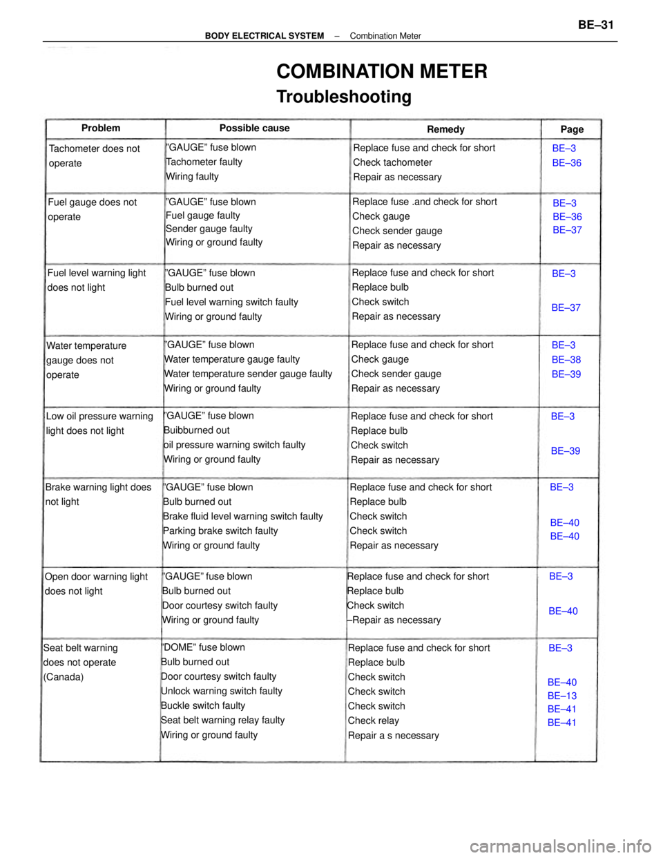
Replace fuse and check for short
Replace bulb
Check switch
Check switch
Check switch
Check relay
Repair a s necessary ºDOMEº fuse blown
Bulb burned out
Door courtesy switch faulty
Unlock warning switch faulty
Buckle switch faulty
Seat belt warning relay faulty
Wiring or ground faultyºGAUGEº fuse blown
Bulb burned out
Brake fluid level warning switch faulty
Parking brake switch faulty
Wiring or ground faultyReplace fuse and check for short
Replace bulb
Check switch
Check switch
Repair as necessary ºGAUGEº fuse blown
Water temperature gauge faulty
Water temperature sender gauge faulty
Wiring or ground faulty
ºGAUGEº fuse blown
Buibburned out
oil pressure warning switch faulty
Wiring or ground faultyºGAUGEº fuse blown
Bulb burned out
Fuel level warning switch faulty
Wiring or ground faulty
Replace fuse and check for short
Replace bulb
Check switch
±Repair as necessaryReplace fuse and check for short
Replace bulb
Check switch
Repair as necessary
Replace fuse and check for short
Replace bulb
Check switch
Repair as necessaryReplace fuse and check for short
Check gauge
Check sender gauge
Repair as necessaryReplace fuse .and check for short
Check gauge
Check sender gauge
Repair as necessary
COMBINATION METER
Troubleshooting
ºGAUGEº fuse blown
Bulb burned out
Door courtesy switch faulty
Wiring or ground faultyReplace fuse and check for short
Check tachometer
Repair as necessary
ºGAUGEº fuse blown
Fuel gauge faulty
Sender gauge faulty
Wiring or ground faultyºGAUGEº fuse blown
Tachometer faulty
Wiring faulty
Low oil pressure warning
light does not lightWater temperature
gauge does not
operate
Seat belt warning
does not operate
(Canada)Tachometer does not
operate
Brake warning light does
not lightFuel gauge does not
operate
Open door warning light
does not lightFuel level warning light
does not light
BE±40
BE±13
BE±41
BE±41BE±3
BE±38
BE±39BE±3
BE±36
BE±37 Possible cause
BE±3
BE±36
BE±40
BE±40 Problem
Remedy
BE±40BE±39BE±37Page
BE±3BE±3
BE±3
BE±3
BE±3
± BODY ELECTRICAL SYSTEMCombination MeterBE±31
Page 778 of 2389
Light Control Rheostat
TAIL Fuse
IGN Fuse
Water Temperature Sender Gauge
Ground
Seat Beh Warning Relay
Brake Fluid Level Warning Switch and Parking
Brake Switch
CHARGE Fuse
TCCS ECU
A.B.S. ECU
Cruise Control ECU and ECT ECU
Ground
Fuel Sender Gauge Terminal 3
Fuel Sender Gauge Terminal 2
GAUGE Fuse
DOME Fuse
Door Courtesy Switch
Low Oil Pressure Switch
Light Failure Sensor
Combination Meter and Gauges
(w/o Tachometer)
Turn Signal Switch Terminal 28
Ground
Turn Signal Switch Terminal 25
Turn Signal Switch Terminal 23 (USA)
HEAD±HI (RH) Fuse (CANADA)
A/T Oil Temperature Switch
COMBINATION METER CIRCUIT
Wiring Connector Side
No.
± BODY ELECTRICAL SYSTEMCombination MeterBE±32
Page 779 of 2389
Light Control Rheostat
TAIL Fuse
IGN Fuse
Water Temperature Sender Gauge
Ground
Seat Belt Warning Relay
Brake Fluid Level Warning Switch and Parking
Brake Switch
CHARGE Fuse
TCCS ECU ,
A. B. S. ECU
Cruise Control ECU and ECT ECU
Ground
Fuel Sender Gauge Terminal 3
Fuel Sender Gauge Terminal 2
. GAUGE Fuse
DOME Fuse
Door Courtesy Switch
Low Oil Pressure Switch
Light Failure Sensor
Turn Signal Switch Terminal 28
Ground
Turn Signal Switch Terminal 25
Turn Signal Switch Terminal 23 (USA)
HEAD±HI (RH) Fuse (CANADA)
A/T Oil Temperature Switch
Igniter
Combination Meter and Gauges
(w/ Tachometer)
COMBINATION METER CIRCUIT
Wiring Connector Side
No.
± BODY ELECTRICAL SYSTEMCombination MeterBE±33
Page 828 of 2389
Vacuum Switch
(w/ A.B.S.) (w/o A.B.S.)ECT Computer
Wire Harness Side
Alternator
Wire Harness SideBrake Fluid Level
Warning Switch
Connectors
Cruise Control Computer
Neutral Start SwitchStop Light Switch
Parking Brake SW
Vacuum PumpSpeed SensorControl SW
Clutch SW Main SW
Actuator
± BODY ELECTRICAL SYSTEMCruise Control SystemBE±70
Page 840 of 2389

INSPECT PARKING BRAKE SWITCH OPERATION
Disconnect connector from parking brake switch.
Is parking brake switch operation normal? (See page
BE±90) INSPECT GROUND CONNECTION
Disconnect connector from brake level warning switch.
Is there continuity between terminal 2 of wire harness side
connector and body gronud?
Short circuit in wire harness between terminal 12 of
computer and terminal 1 of parking brake switch,
terminal 1 of brake fluid level warning switch or terminal
2 of alternator. INSPECT BRAKE WARNING SWITCH
Is brake fluid level warning switch operation nomal?
(See page BE±38)
wOpen circuit in wire harness between terminal 2
and body ground.
wBody ground faulty.
INSPECTION OF PARKING BRAKE SWITCH CIRCUIT
Is there no voltage between terminal 12 and body ground
with parking brake pulled up?
!s there battery voltage between terminal 12 and body
ground with parking brake released? Disconnect connector from computer and inspect connector
on wire harness side as follows.
Open circuit in wire harness between terminal 12 of
computer and terminal of parking brake switch. INSPECT ALTERNATOR OPERATION
is alternator operation normal? (See page CH±4)
Remove CHARGE fuse and ignition switch tuned on. Connect the connector to brake warning switch.
Connect connector to parking brake switch.
BRAKE FLUID LEVEL
WARNING SWITCH
Replace brake warning switch.
Replace parking brake switch.
PARKING BRAKE SWITCH
Turn ignition switch off.
Replace computer.Replace alternator.
ALTERNATOR
COMPUTER
Ye s
Ye s Ye s
Ye s Ye sYe s
± BODY ELECTRICAL SYSTEMCruise Control SystemBE±82
Page 858 of 2389

OPERATIONAL TEST OF BRAKE
BOOSTER
HINT: If there is leakage or lack of vacuum, repair before
testing. If available, use a brake booster tester to check the
booster operating condition.
1. OPERATING CHECK
(a) Depress the brake pedal several times with the en-
gine stopped, and check that is no change in the ped-
al reserve distance.
(b) Depress the brake pedal and start the engine. If the
pedal goes down slightly, operation is normal.
2. AIR TIGHTNESS CHECK
(a) Start the engine and stop it after one or two minutes.
Depress the brake pedal several times slowly. If the
pedal goes down furtherest the first time, but gradual-
ly rises after the second or third time, the booster is air
tight.
(b) Depress the brake pedal while the engine is running,
and stop it with the pedal depressed. If there is no
change in pedal reserve travel after holding the pedal
for thirty seconds, the booster is air tight.
BLEEDING OF BRAKE SYSTEM
HINT: If any work is done on the brake system or if air is sus-
pected in the brake lines, bleed the system of air.
NOTICE: Do not let brake fluid remain on a painted surface.
Wash it off immediately.
1. FILL BRAKE RESERVOIR WITH BRAKE FLUID
Check the fluid level in the reservoir. If necessary, add
brake fluid. 5. CHECK THAT PEDAL RESERVE DISTANCE IS
CORRECT
Release the parking brake. With engine running, depress
the pedal and measure the pedal reserve distance, as
shown.
Pedal reserve distance from asphalt sheet at 50 kg
(110.2 1b): More than 85 mm, (3.35 in.)
If incorrect, troubleshoot the brake system.
2. BLEED MASTER CYLINDER
HINT: If the master cylinder was disassembled or if the res-
ervoir becomes empty, bleed the air from the master cylin-
der.
(a) Disconnect the brake tubes from the master cylinder.
(b) Depress the brake pedal and hold it.
± BRAKE SYSTEMChecks and AdjustmentsBR±7


