1985 FORD GRANADA warning
[x] Cancel search: warningPage 135 of 255
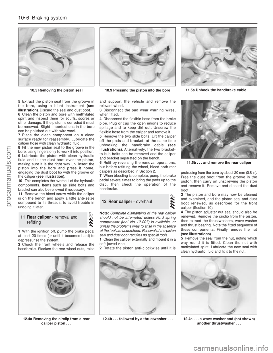
5Extract the piston seal from the groove in
the bore, using a blunt instrument (see
illustration). Discard the seal and dust boot.
6Clean the piston and bore with methylated
spirit and inspect them for scuffs, scores or
other damage. If the piston is corroded it must
be renewed. Slight imperfections in the bore
can be polished out with wire wool.
7Place the clean component on a clean
surface ready for reassembly. Lubricate the
caliper hose with clean hydraulic fluid.
8Fit the new piston seal to the groove in the
bore, using fingers only to work it into position.
9Lubricate the piston with clean hydraulic
fluid and fit the dust boot over the piston,
making sure it is the right way up. Insert the
piston into the bore and press it home,
engaging the dust boot lip with the groove on
the caliper (see illustration).
10This completes the overhaul of the hydraulic
components. Items such as slide bolts and
bracket can also be renewed if necessary.
11Remove the bleed screw while the caliper
is on the bench and apply a little anti-seize
compound to its threads, to avoid trouble in
undoing it later.
1With the ignition off, pump the brake pedal
at least 20 times (or until it becomes hard) to
depressurise the system.
2Chock the front wheels and release the
handbrake. Slacken the rear wheel nuts, raiseand support the vehicle and remove the
relevant wheel.
3Disconnect the pad wear warning wires,
when fitted.
4Disconnect the flexible hose from the brake
pipe. Plug or cap the open unions to reduce
spillage and to keep dirt out. Unscrew the
flexible hose from the caliper and remove it.
5Remove the two slide bolts. Lift the caliper
off the pads and bracket, at the same time
unhooking the handbrake cable (see
illustrations). Alternatively, the two bracket-
to-hub bolts can be removed and the caliper
and bracket separated on the bench.
6Refit by reversing the removal operations,
but before refitting the wheel, bleed both rear
calipers as described in Section 2.
7When bleeding is complete, pump the brake
pedal several times to bring the pads up to the
disc, then check the operation of the
handbrake.
Note: Complete dismantling of the rear caliper
should not be attempted unless Ford spring
compressor (tool No 12-007) is available. or
unless the problems likely to arise in the absence
of the tool are understood. Renewal of the piston
seal and dust boot requires no special tools.
1Clean the caliper externally and mount it in a
soft-jawed vice.
2Rotate the piston anti-clockwise until it isprotruding from the bore by about 20 mm (0.8 in).
Free the dust boot from the groove in the
piston, then carry on unscrewing the piston
and remove it. Remove and discard the dust
boot.
3The piston and bore may now be cleaned
and examined, and the piston seal and dust
boot renewed, as described for the front
caliper (Section 10).
4The piston adjuster nut seal should also be
renewed. Remove the circlip from the piston,
then extract the thrustwashers, wave washer
and thrust bearing. Note the fitted sequence of
these components. Finally remove the nut
(see illustrations).
5Remove the seal from the nut, noting which
way round it is fitted. Clean the nut with
methylated spirit. Lubricate the new seal with
clean hydraulic fluid and fit it to the nut.
12Rear caliper - overhaul
11Rear caliper - removal and
refitting
10•6Braking system
10.5 Removing the piston seal
12.4a Removing the circlip from a rear
caliper piston . . .12.4b . . . followed by a thrustwasher . . .
11.5b . . . and remove the rear caliper
10.9 Pressing the piston into the bore11.5a Unhook the handbrake cable . . .
12.4c . . . a wave washer and (not shown)
another thrustwasher . . .
procarmanuals.com
Page 140 of 255
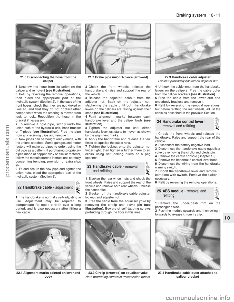
5Unscrew the hose from its union on the
caliper and remove it (see illustration).
6Refit by reversing the removal operations,
then bleed the appropriate part of the
hydraulic system (Section 2). In the case of the
front hoses, check that they are not kinked or
twisted, and that they do not contact other
components when the steering is moved from
lock to lock. Reposition the hose in the
bracket if necessary.
7To remove a rigid pipe, simply undo the
union nuts at the hydraulic unit, hose bracket
or T-piece (see illustration). Free the pipe
from any retaining clips and remove it.
8New pipes can be bought ready-made, with
the unions attached. Some garages and motor
factors will make up pipes to order, using the
old pipe as a pattern. If purchasing proprietary
pipes made of copper alloy or similar material,
follow the manufacturer’s instructions carefully
concerning bending, provision of extra clips
etc.
9Fit and secure the new pipe and tighten the
union nuts, bleed the appropriate part of the
hydraulic system (Section 2).
1The handbrake is normally self-adjusting in
use. Adjustment may be required to
compensate for cable stretch over a long
period, and is also necessary after fitting a
new cable.2Chock the front wheels, release the
handbrake and raise and support the rear of
the vehicle.
3Release the adjuster locknut from the
adjuster nut. Back off the adjuster nut,
slackening the cable until both handbrake
levers on the calipers are resting against their
stops (see illustration).
4Paint alignment marks between each
handbrake lever and the caliper body (see
illustration).
5Tighten the adjuster nut until either
handbrake lever just starts to move - as shown
by the alignment marks.
6Apply the handbrake and release it a few
times to equalise the cable runs.
7Tighten the locknut onto the adjuster nut
finger tight, then tighten a further three to six
clicks using self-locking pliers or a peg
spanner.
1Slacken the rear wheel nuts and chock the
front wheels. Raise and support the rear of the
vehicle and remove both rear wheels. Release
the handbrake.
2Slacken off the handbrake cable adjuster
locknut and adjuster nut.
3Free the cable from the equaliser yoke by
removing the circlip and clevis pin (see
illustration). Beware of self-tapping screws
protruding through the floor in this area.4Unhook the cable inner from the handbrake
levers on the calipers. Free the cable outer
from the caliper brackets (see illustration).
5Free the cable from the lower arm and
underbody brackets and remove it.
6Refit by reversing the removal operations,
but before refitting the rear wheels, adjust the
cable as described in the previous Section.
1Chock the front wheels and release the
handbrake. Raise and support the rear of the
vehicle.
2Disconnect the battery negative lead.
3Disconnect the handbrake cable equaliser
yoke by removing the circlip and clevis pin.
4Remove the centre console (Chapter 12).
5Remove the handbrake control lever boot.
6Disconnect the wiring from the handbrake
warning switch.
7Unbolt the handbrake lever and remove it,
complete with switch. Remove the switch if
necessary.
8Refit by reversing the removal operations.
1Remove the under-dash trim on the
passenger’s side.
2Push the module upwards and then swing it
forwards to release it from its clip.
25ABS module - removal and
refitting
24Handbrake control lever -
removal and refitting
23Handbrake cable - removal
and refitting
22Handbrake cable - adjustment
Braking system 10•11
10
21.5 Disconnecting the hose from the
caliper21.7 Brake pipe union T-piece (arrowed)22.3 Handbrake cable adjuster
Locknut previously backed off adjuster nut
22.4 Alignment marks painted on lever and
body23.3 Circlip (arrowed) on equaliser yoke
Note protruding screws in transmission tunnel23.4 Handbrake cable outer attached to
caliper bracket
procarmanuals.com
Page 153 of 255
1With the strut removed, clamp it in a vice
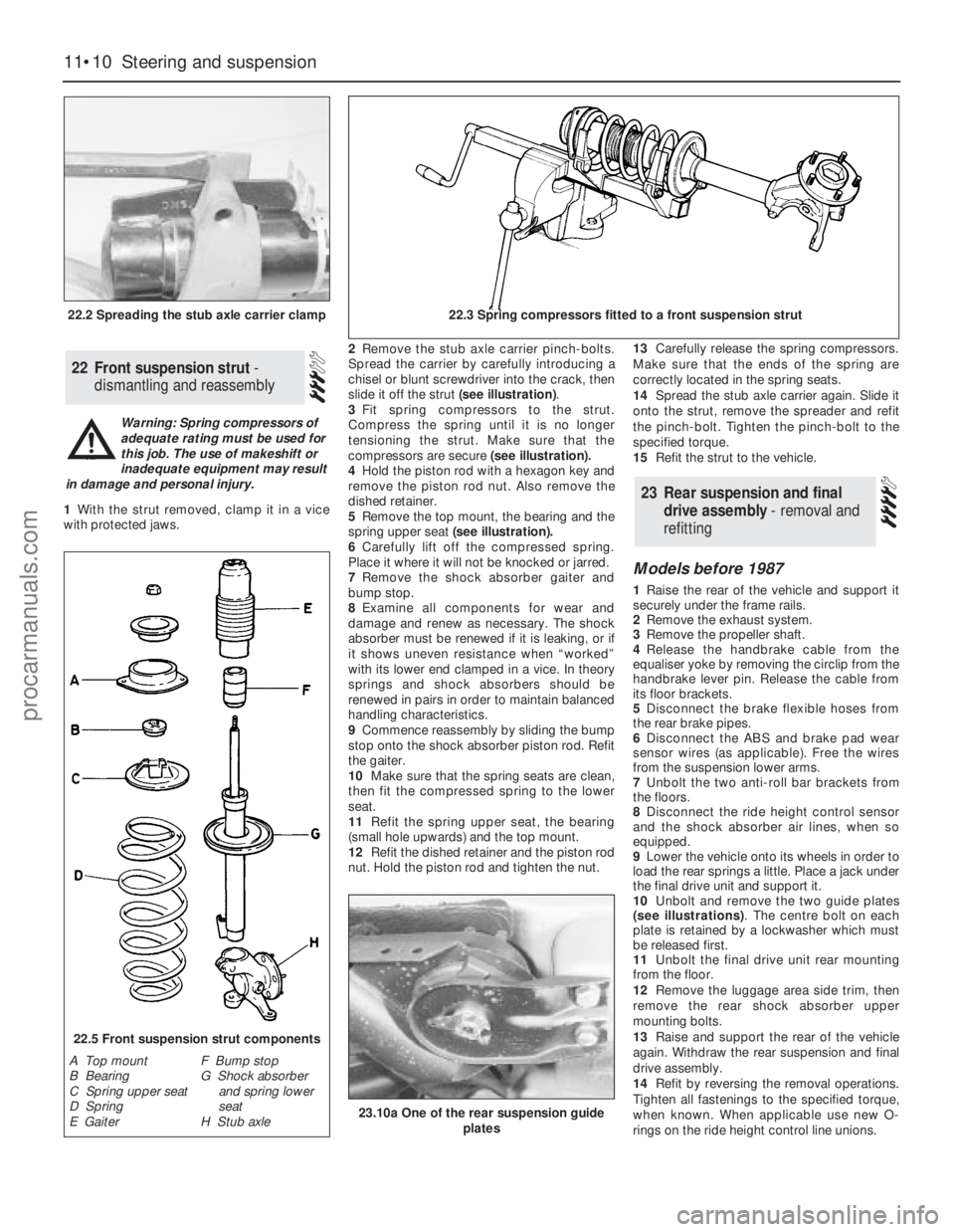
with protected jaws.2Remove the stub axle carrier pinch-bolts.
Spread the carrier by carefully introducing a
chisel or blunt screwdriver into the crack, then
slide it off the strut (see illustration).
3Fit spring compressors to the strut.
Compress the spring until it is no longer
tensioning the strut. Make sure that the
compressors are secure (see illustration).
4Hold the piston rod with a hexagon key and
remove the piston rod nut. Also remove the
dished retainer.
5Remove the top mount, the bearing and the
spring upper seat(see illustration).
6Carefully lift off the compressed spring.
Place it where it will not be knocked or jarred.
7Remove the shock absorber gaiter and
bump stop.
8Examine all components for wear and
damage and renew as necessary. The shock
absorber must be renewed if it is leaking, or if
it shows uneven resistance when “worked”
with its lower end clamped in a vice. In theory
springs and shock absorbers should be
renewed in pairs in order to maintain balanced
handling characteristics.
9Commence reassembly by sliding the bump
stop onto the shock absorber piston rod. Refit
the gaiter.
10Make sure that the spring seats are clean,
then fit the compressed spring to the lower
seat.
11Refit the spring upper seat, the bearing
(small hole upwards) and the top mount.
12Refit the dished retainer and the piston rod
nut. Hold the piston rod and tighten the nut.13Carefully release the spring compressors.
Make sure that the ends of the spring are
correctly located in the spring seats.
14Spread the stub axle carrier again. Slide it
onto the strut, remove the spreader and refit
the pinch-bolt. Tighten the pinch-bolt to the
specified torque.
15Refit the strut to the vehicle.
Models before 1987
1Raise the rear of the vehicle and support it
securely under the frame rails.
2Remove the exhaust system.
3Remove the propeller shaft.
4Release the handbrake cable from the
equaliser yoke by removing the circlip from the
handbrake lever pin. Release the cable from
its floor brackets.
5Disconnect the brake flexible hoses from
the rear brake pipes.
6Disconnect the ABS and brake pad wear
sensor wires (as applicable). Free the wires
from the suspension lower arms.
7Unbolt the two anti-roll bar brackets from
the floors.
8Disconnect the ride height control sensor
and the shock absorber air lines, when so
equipped.
9Lower the vehicle onto its wheels in order to
load the rear springs a little. Place a jack under
the final drive unit and support it.
10Unbolt and remove the two guide plates
(see illustrations). The centre bolt on each
plate is retained by a lockwasher which must
be released first.
11Unbolt the final drive unit rear mounting
from the floor.
12Remove the luggage area side trim, then
remove the rear shock absorber upper
mounting bolts.
13Raise and support the rear of the vehicle
again. Withdraw the rear suspension and final
drive assembly.
14Refit by reversing the removal operations.
Tighten all fastenings to the specified torque,
when known. When applicable use new O-
rings on the ride height control line unions.
23Rear suspension and final
drive assembly - removal and
refitting
22Front suspension strut -
dismantling and reassembly
11•10Steering and suspension
22.2 Spreading the stub axle carrier clamp22.3 Spring compressors fitted to a front suspension strut
22.5 Front suspension strut components
A Top mount
B Bearing
C Spring upper seat
D Spring
E GaiterF Bump stop
G Shock absorber
and spring lower
seat
H Stub axle
Warning: Spring compressors of
adequate rating must be used for
this job. The use of makeshift or
inadequate equipment may result
in damage and personal injury.
23.10a One of the rear suspension guide
plates
procarmanuals.com
Page 162 of 255
4Have an assistant support the tailgate.
Disconnect the struts from the tailgate.
5Jam the tailgate latch with a piece of wood
or cardboard so that the tailgate cannot shut.
Lower the tailgate.
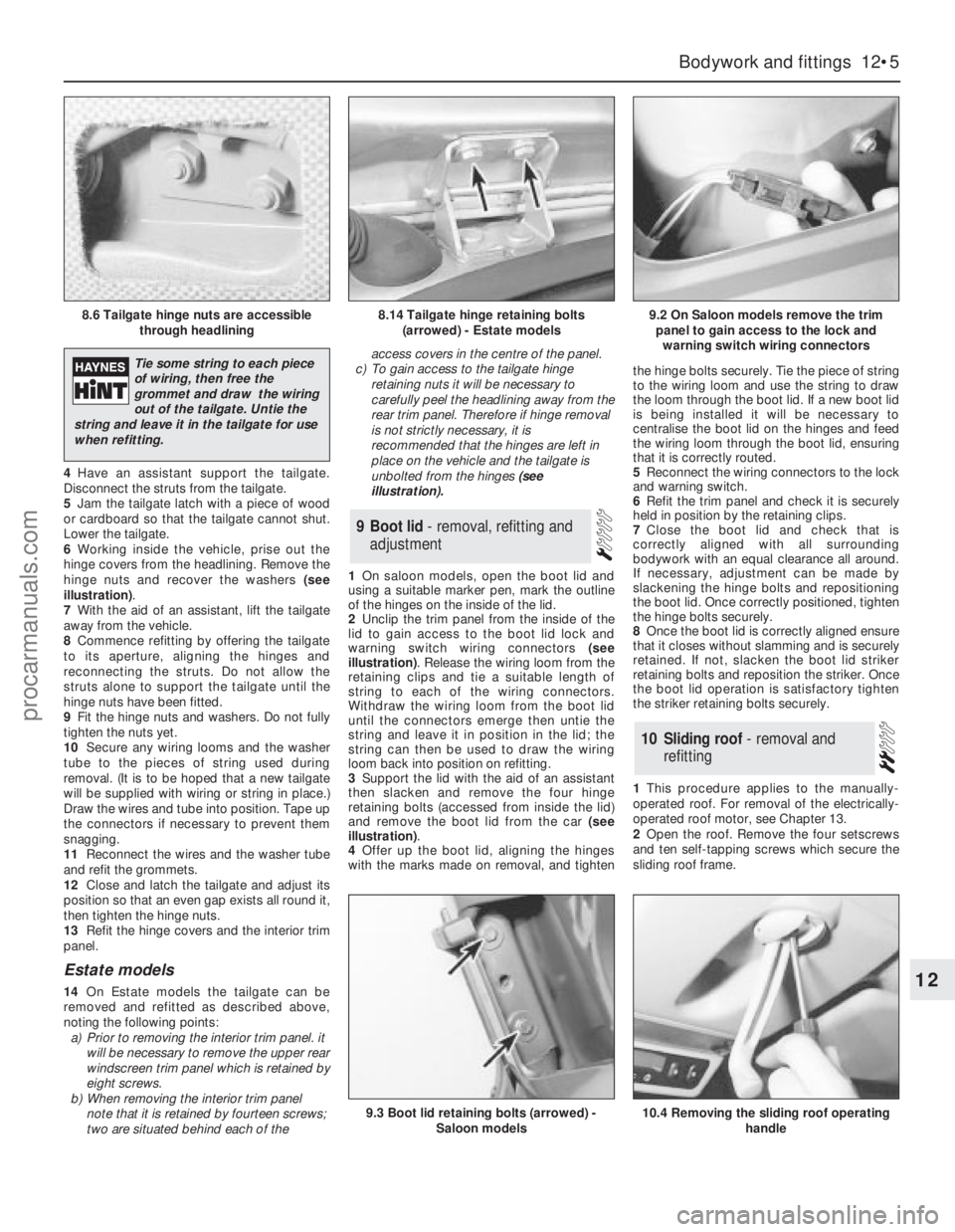
6Working inside the vehicle, prise out the
hinge covers from the headlining. Remove the
hinge nuts and recover the washers (see
illustration).
7With the aid of an assistant, lift the tailgate
away from the vehicle.
8Commence refitting by offering the tailgate
to its aperture, aligning the hinges and
reconnecting the struts. Do not allow the
struts alone to support the tailgate until the
hinge nuts have been fitted.
9Fit the hinge nuts and washers. Do not fully
tighten the nuts yet.
10Secure any wiring looms and the washer
tube to the pieces of string used during
removal. (It is to be hoped that a new tailgate
will be supplied with wiring or string in place.)
Draw the wires and tube into position. Tape up
the connectors if necessary to prevent them
snagging.
11Reconnect the wires and the washer tube
and refit the grommets.
12Close and latch the tailgate and adjust its
position so that an even gap exists all round it,
then tighten the hinge nuts.
13Refit the hinge covers and the interior trim
panel.
Estate models
14On Estate models the tailgate can be
removed and refitted as described above,
noting the following points:
a)Prior to removing the interior trim panel. it
will be necessary to remove the upper rear
windscreen trim panel which is retained by
eight screws.
b)When removing the interior trim panel
note that it is retained by fourteen screws;
two are situated behind each of theaccess covers in the centre of the panel.
c)To gain access to the tailgate hinge
retaining nuts it will be necessary to
carefully peelthe headlining away from the
rear trim panel. Therefore if hinge removal
is not strictly necessary, it is
recommended that the hinges are left in
place on the vehicle and the tailgate is
unbolted from the hinges (see
illustration).
1On saloon models, open the boot lid and
using a suitable marker pen, mark the outline
of the hinges on the inside of the lid.
2Unclip the trim panel from the inside of the
lid to gain access to the boot lid lock and
warning switch wiring connectors (see
illustration). Release the wiring loom from the
retaining clips and tie a suitable length of
string to each of the wiring connectors.
Withdraw the wiring loom from the boot lid
until the connectors emerge then untie the
string and leave it in position in the lid; the
string can then be used to draw the wiring
loom back into position on refitting.
3Support the lid with the aid of an assistant
then slacken and remove the four hinge
retaining bolts (accessed from inside the lid)
and remove the boot lid from the car (see
illustration).
4Offer up the boot lid, aligning the hinges
with the marks made on removal, and tightenthe hinge bolts securely. Tie the piece of string
to the wiring loom and use the string to draw
the loom through the boot lid. If a new boot lid
is being installed it will be necessary to
centralise the boot lid on the hinges and feed
the wiring loom through the boot lid, ensuring
that it is correctly routed.
5Reconnect the wiring connectors to the lock
and warning switch.
6Refit the trim panel and check it is securely
held in position by the retaining clips.
7Close the boot lid and check that is
correctly aligned with all surrounding
bodywork with an equal clearance all around.
If necessary, adjustment can be made by
slackening the hinge bolts and repositioning
the boot lid. Once correctly positioned, tighten
the hinge bolts securely.
8Once the boot lid is correctly aligned ensure
that it closes without slamming and is securely
retained. If not, slacken the boot lid striker
retaining bolts and reposition the striker. Once
the boot lid operation is satisfactory tighten
the striker retaining bolts securely.
1This procedure applies to the manually-
operated roof. For removal of the electrically-
operated roof motor, see Chapter 13.
2Open the roof. Remove the four setscrews
and ten self-tapping screws which secure the
sliding roof frame.
10Sliding roof - removal and
refitting
9Boot lid - removal, refitting and
adjustment
Bodywork and fittings 12•5
12
8.6 Tailgate hinge nuts are accessible
through headlining8.14 Tailgate hinge retaining bolts
(arrowed) - Estate models9.2 On Saloon models remove the trim
panel to gain access to the lock and
warning switch wiring connectors
9.3 Boot lid retaining bolts (arrowed) -
Saloon models10.4 Removing the sliding roof operating
handle
Tie some string to each piece
of wiring, then free the
grommet and draw the wiring
out of the tailgate. Untie the
string and leave it in the tailgate for use
when refitting.
procarmanuals.com
Page 164 of 255
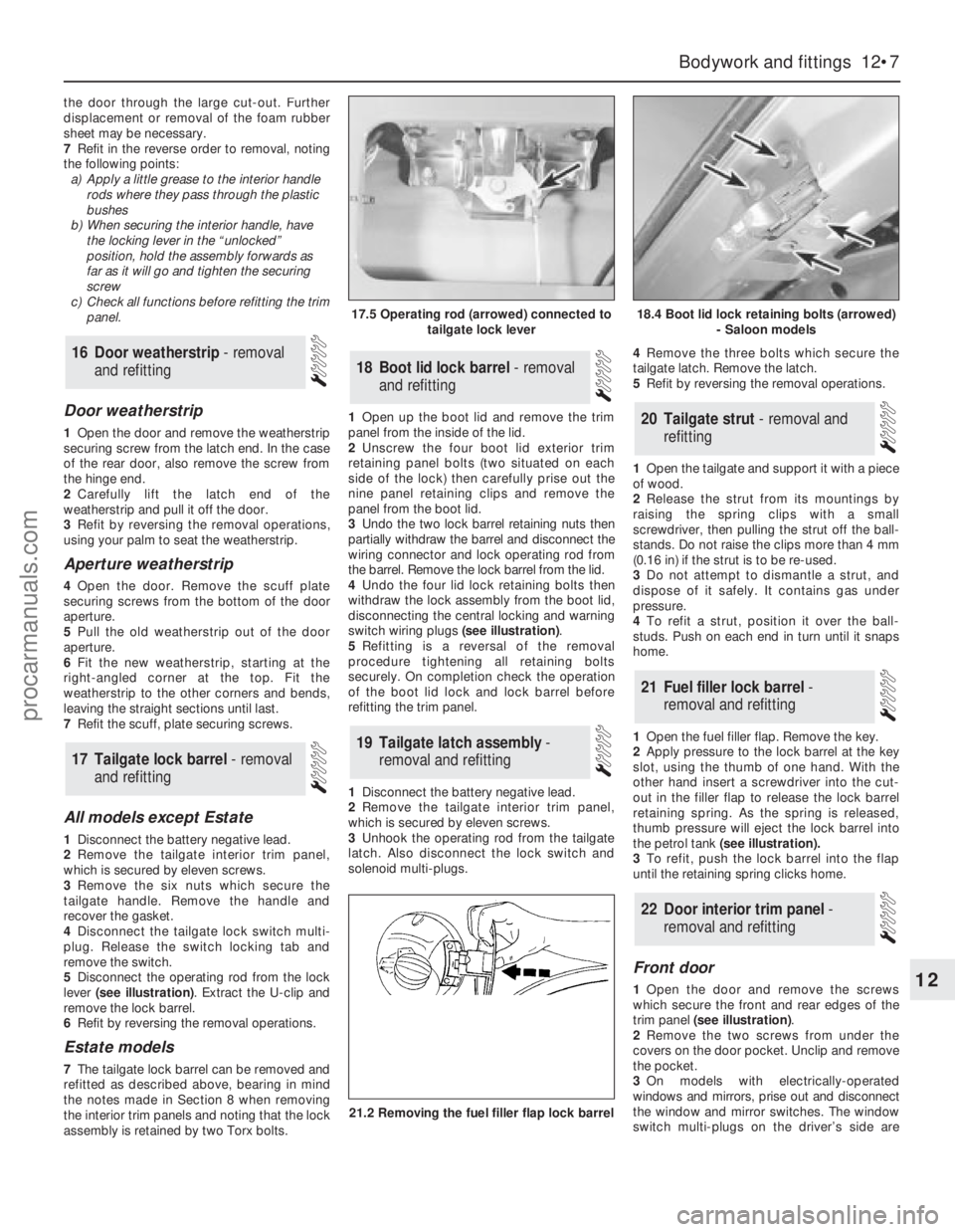
the door through the large cut-out. Further
displacement or removal of the foamrubber
sheet may be necessary.
7Refit in the reverse order to removal, noting
the following points:
a)Apply a little grease to the interior handle
rods where they pass through the plastic
bushes
b)When securing the interior handle, have
the locking lever in the “unlocked”
position, hold the assembly forwards as
far as itwill go and tighten the securing
screw
c)Check all functions before refitting the trim
panel.
Door weatherstrip
1Open the door and remove the weatherstrip
securing screw from the latch end. In the case
of the rear door, also remove the screw from
the hinge end.
2Carefully lift the latch end of the
weatherstrip and pull it off the door.
3Refit by reversing the removal operations,
using your palm to seat the weatherstrip.
Aperture weatherstrip
4Open the door. Remove the scuff plate
securing screws from the bottom of the door
aperture.
5Pull the old weatherstrip out of the door
aperture.
6Fit the new weatherstrip, starting at the
right-angled corner at the top. Fit the
weatherstrip to the other corners and bends,
leaving the straight sections until last.
7Refit the scuff, plate securing screws.
All models except Estate
1Disconnect the battery negative lead.
2Remove the tailgate interior trim panel,
which is secured by eleven screws.
3Remove the six nuts which secure the
tailgate handle. Remove the handle and
recover the gasket.
4Disconnect the tailgate lock switch multi-
plug. Release the switch locking tab and
remove the switch.
5Disconnect the operating rod from the lock
lever (see illustration). Extract the U-clip and
remove the lock barrel.
6Refit by reversing the removal operations.
Estate models
7The tailgate lock barrel can be removed and
refitted as described above, bearing in mind
the notes made in Section 8 when removing
the interior trim panels and noting that the lock
assembly is retained by two Torx bolts.1Open up the boot lid and remove the trim
panel from the inside of the lid.
2Unscrew the four boot lid exterior trim
retaining panel bolts (two situated on each
side of the lock) then carefully prise out the
nine panel retaining clips and remove the
panel from the boot lid.
3Undo the two lock barrel retaining nuts then
partially withdraw the barrel and disconnect the
wiring connector and lock operating rod from
the barrel. Remove the lock barrel from the lid.
4Undo the four lid lock retaining bolts then
withdraw the lock assembly from the boot lid,
disconnecting the central locking and warning
switch wiring plugs (see illustration).
5Refitting is a reversal of the removal
procedure tightening all retaining bolts
securely. On completion check the operation
of the boot lid lock and lock barrel before
refitting the trim panel.
1Disconnect the battery negative lead.
2Remove the tailgate interior trim panel,
which is secured by eleven screws.
3Unhook the operating rod from the tailgate
latch. Also disconnect the lock switch and
solenoid multi-plugs.4Remove the three bolts which secure the
tailgate latch. Remove the latch.
5Refit by reversing the removal operations.
1Open the tailgate and support it with a piece
of wood.
2Release the strut from its mountings by
raising the spring clips with a small
screwdriver, then pulling the strut off the ball-
stands. Do not raise the clips more than 4 mm
(0.16 in) if the strut is to be re-used.
3Do not attempt to dismantle a strut, and
dispose of it safely. It contains gas under
pressure.
4To refit a strut, position it over the ball-
studs. Push on each end in turn until it snaps
home.
1Open the fuel filler flap. Remove the key.
2Apply pressure to the lock barrel at the key
slot, using the thumb of one hand. With the
other hand insert a screwdriver into the cut-
out in the filler flap to release the lock barrel
retaining spring. As the spring is released,
thumb pressure will eject the lock barrel into
the petrol tank (see illustration).
3To refit, push the lock barrel into the flap
until the retaining spring clicks home.
Front door
1Open the door and remove the screws
which secure the front and rear edges of the
trim panel (see illustration).
2Remove the two screws from under the
covers on the door pocket. Unclip and remove
the pocket.
3On models with electrically-operated
windows and mirrors, prise out and disconnect
the window and mirror switches. The window
switch multi-plugs on the driver’s side are
22Door interior trim panel -
removal and refitting
21Fuel filler lock barrel -
removal and refitting
20Tailgate strut - removal and
refitting
19Tailgate latch assembly -
removal and refitting
18Boot lid lock barrel - removal
and refitting
17Tailgate lock barrel - removal
and refitting
16Door weatherstrip - removal
and refitting
Bodywork and fittings 12•7
12
17.5 Operating rod (arrowed) connected to
tailgate lock lever18.4 Boot lid lock retaining bolts (arrowed)
- Saloon models
21.2 Removing the fuel filler flap lock barrel
procarmanuals.com
Page 169 of 255
10Remove the securing screws and detach
the C and D-pillar trim panels.
11Remove the top of the facia panel.
12Remove the securing screw from the base
of the A-pillar trim on each side. Detach the A-
pillar trim panels.
13Remove the headlining through the
tailgate, peeling it back from around the sliding
roof (when applicable - see paragraph 15).
14Refitting is essentially a reversal of the
removal procedure. The services of an
assistant will be required during the initial
stages of refitting.
15When a sliding roof is fitted, the headlining
is secured around the aperture with double-
sided adhesive tape.
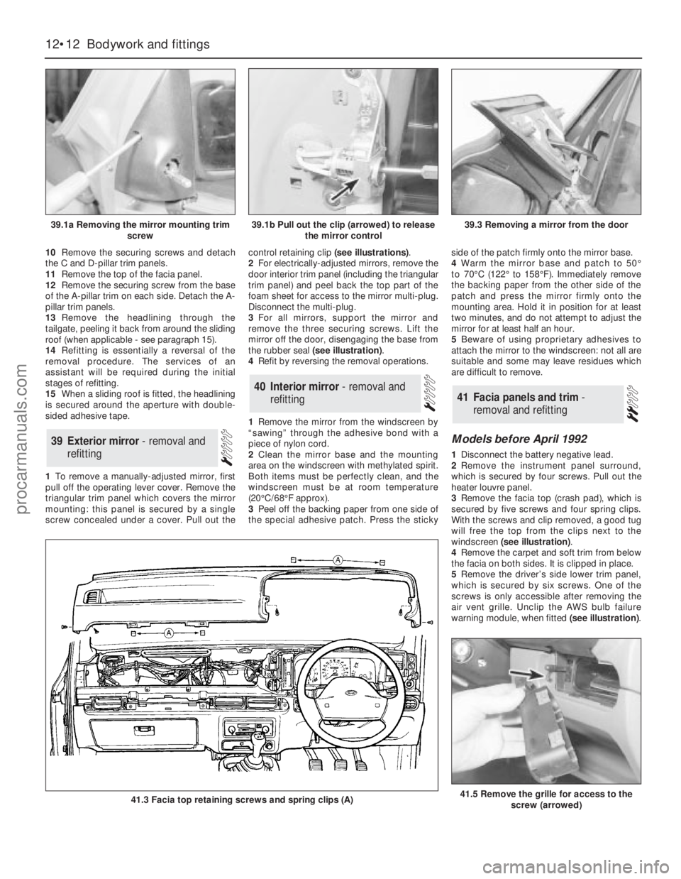
1To remove a manually-adjusted mirror, first
pull off the operating lever cover. Remove the
triangular trim panel which covers the mirror
mounting: this panel is secured by a single
screw concealed under a cover. Pull out thecontrol retaining clip (see illustrations).
2For electrically-adjusted mirrors, remove the
door interior trim panel (including the triangular
trim panel) and peel back the top part of the
foam sheet for access to the mirror multi-plug.
Disconnect the multi-plug.
3For all mirrors, support the mirror and
remove the three securing screws. Lift the
mirror off the door, disengaging the base from
the rubber seal (see illustration).
4Refit by reversing the removal operations.
1Remove the mirror from the windscreen by
“sawing” through the adhesive bond with a
piece of nylon cord.
2Clean the mirror base and the mounting
area on the windscreen with methylated spirit.
Both items must be perfectly clean, and the
windscreen must be at room temperature
(20°C/68°F approx).
3Peel off the backing paper from one side of
the special adhesive patch. Press the stickyside of the patch firmly onto the mirror base.
4Warm the mirror base and patch to 50°
to 70°C (122°to 158°F). Immediately remove
the backing paper from the other side of the
patch and press the mirror firmly onto the
mounting area. Hold it in position for at least
two minutes, and do not attempt to adjust the
mirror for at least half an hour.
5Beware of using proprietary adhesives to
attach the mirror to the windscreen: not all are
suitable and some may leave residues which
are difficult to remove.
Models before April 1992
1Disconnect the battery negative lead.
2Remove the instrument panel surround,
which is secured by four screws. Pull out the
heater louvre panel.
3Remove the facia top (crash pad), which is
secured by five screws and four spring clips.
With the screws and clip removed, a good tug
will free the top from the clips next to the
windscreen (see illustration).
4Remove the carpet and soft trim from below
the facia on both sides. It is clipped in place.
5Remove the driver’s side lower trim panel,
which is secured by six screws. One of the
screws is only accessible after removing the
air vent grille. Unclip the AWS bulb failure
warning module, when fitted (see illustration).
41Facia panels and trim -
removal and refitting40Interior mirror - removal and
refitting
39Exterior mirror - removal and
refitting
12•12Bodywork and fittings
39.1a Removing the mirror mounting trim
screw
41.3 Facia top retaining screws and spring clips (A)41.5 Remove the grille for access to the
screw (arrowed)
39.1b Pull out the clip (arrowed) to release
the mirror control39.3 Removing a mirror from the door
procarmanuals.com
Page 171 of 255
12•14Bodywork and fittings
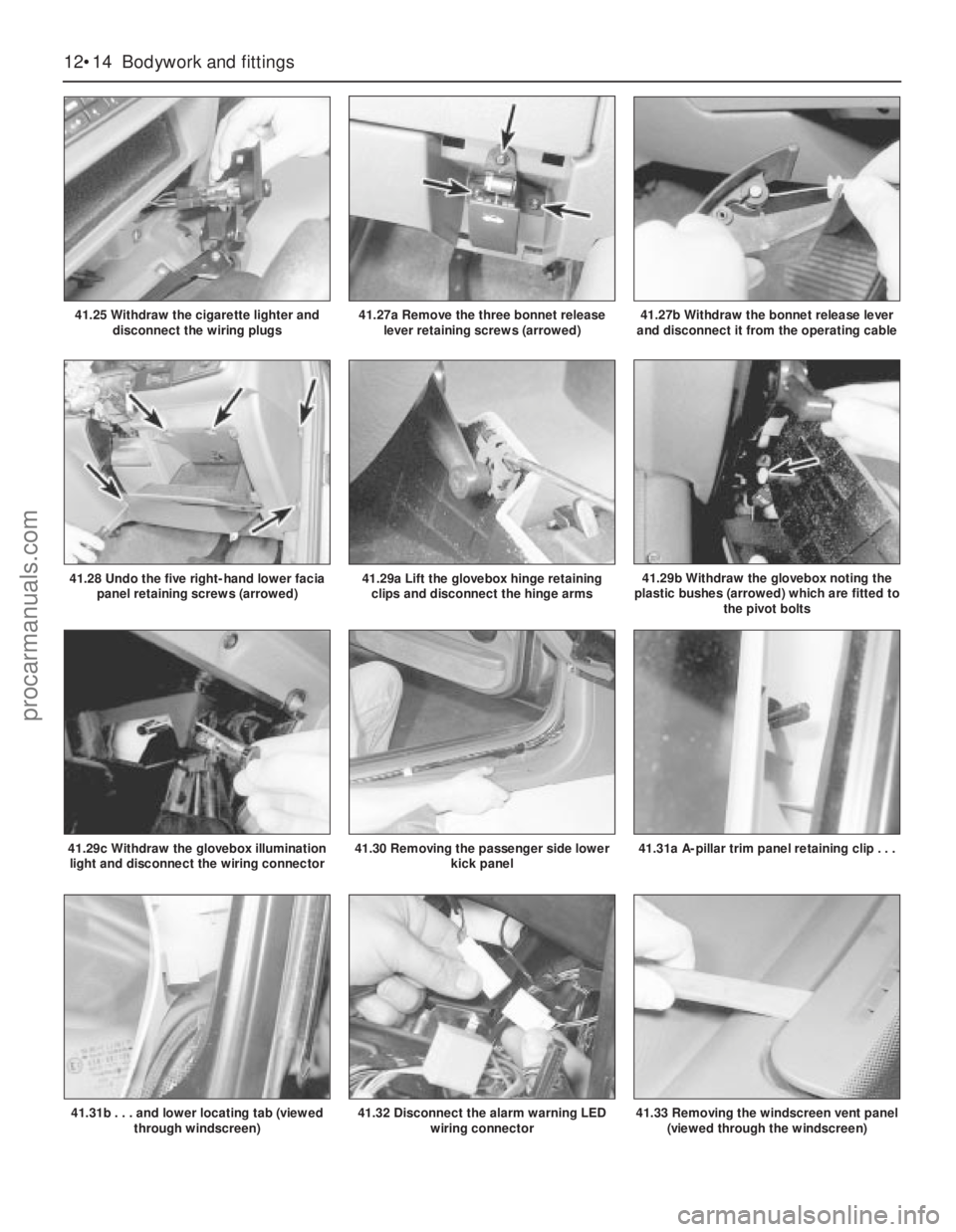
41.25 Withdraw the cigarette lighter and
disconnect the wiring plugs
41.30 Removing the passenger side lower
kick panel
41.29a Lift the glovebox hinge retaining
clips and disconnect the hinge arms41.29b Withdraw the glovebox noting the
plastic bushes (arrowed) which are fitted to
the pivot bolts
41.29c Withdraw the glovebox illumination
light and disconnect the wiring connector
41.28 Undo the five right-hand lower facia
panel retaining screws (arrowed)
41.31a A-pillar trim panel retaining clip . . .
41.31b . . . and lower locating tab (viewed
through windscreen)
41.27a Remove the three bonnet release
lever retaining screws (arrowed)41.27b Withdraw the bonnet release lever
and disconnect it from the operating cable
41.32 Disconnect the alarm warning LED
wiring connector41.33 Removing the windscreen vent panel
(viewed through the windscreen)
procarmanuals.com
Page 172 of 255
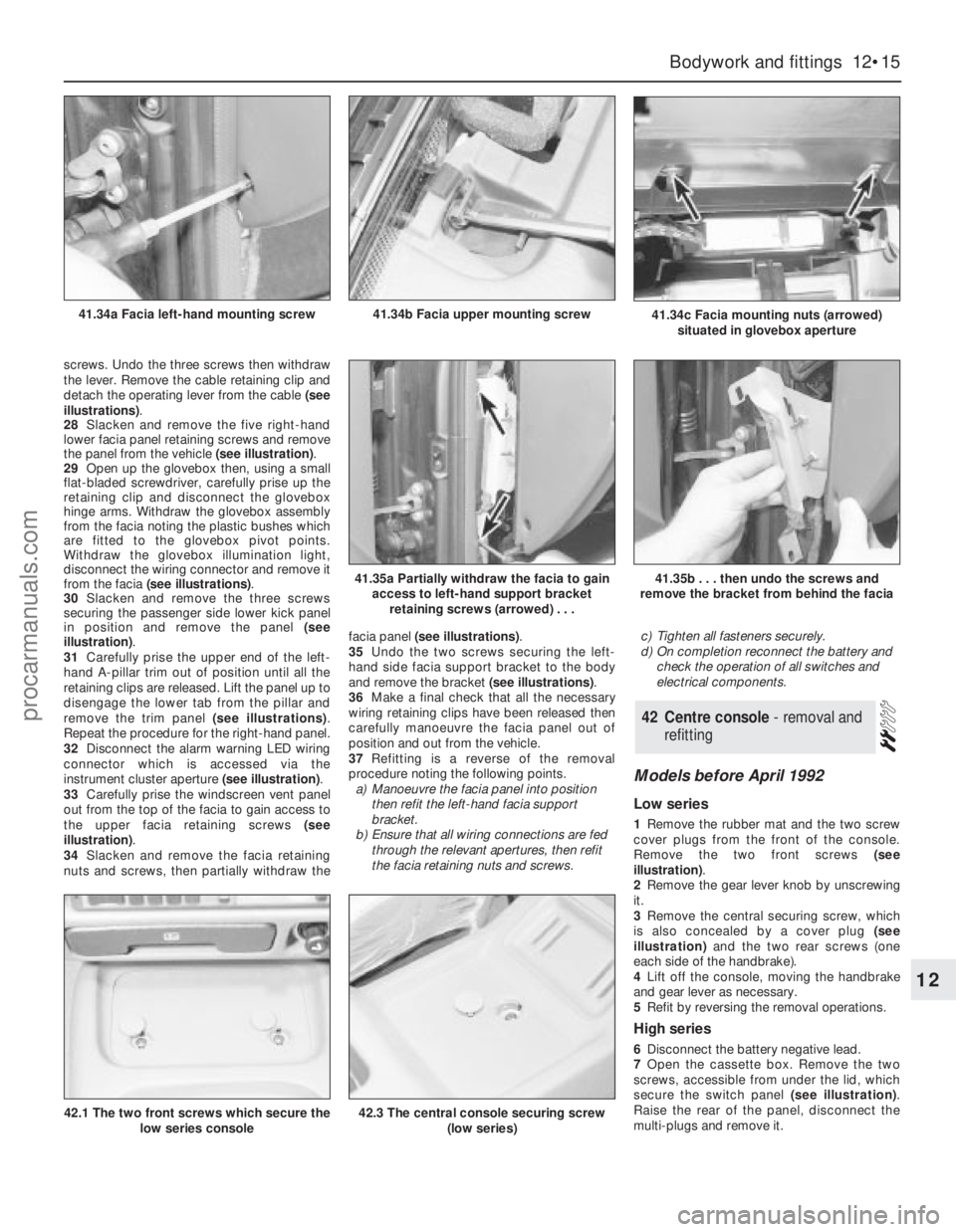
screws. Undo the three screws then withdraw
the lever. Remove the cable retaining clip and
detach the operating lever from the cable (see
illustrations).
28Slacken and remove the five right-hand
lower facia panel retaining screws and remove
the panel from the vehicle (see illustration).
29Open up the glovebox then, using a small
flat-bladed screwdriver, carefully prise up the
retaining clip and disconnect the glovebox
hinge arms. Withdraw the glovebox assembly
from the facia noting the plastic bushes which
are fitted to the glovebox pivot points.
Withdraw the glovebox illumination light,
disconnect the wiring connector and remove it
from the facia (see illustrations).
30Slacken and remove the three screws
securing the passenger side lower kick panel
in position and remove the panel (see
illustration).
31Carefully prise the upper end of the left-
hand A-pillar trim out of position until all the
retaining clips are released. Lift the panel up to
disengage the lower tab from the pillar and
remove the trim panel (see illustrations).
Repeat the procedure for the right-hand panel.
32Disconnect the alarm warning LED wiring
connector which is accessed via the
instrument cluster aperture (see illustration).
33Carefully prise the windscreen vent panel
out from the top of the facia to gain access to
the upper facia retaining screws (see
illustration).
34Slacken and remove the facia retaining
nuts and screws, then partially withdraw thefacia panel (see illustrations).
35Undo the two screws securing the left-
hand side facia support bracket to the body
and remove the bracket (see illustrations).
36Make a final check that all the necessary
wiring retaining clips have been released then
carefully manoeuvre the facia panel out of
position and out from the vehicle.
37Refitting is a reverse of the removal
procedure noting the following points.
a)Manoeuvre the facia panel into position
then refit the left-hand facia support
bracket.
b)Ensure that all wiring connections are fed
through the relevant apertures, then refit
the facia retaining nuts and screws.c)Tighten all fasteners securely.
d)On completion reconnect the battery and
check the operation of all switches and
electrical components.
Models before April 1992
Low series
1Remove the rubber mat and the two screw
cover plugs from the front of the console.
Remove the two front screws (see
illustration).
2Remove the gear lever knob by unscrewing
it.
3Remove the central securing screw, which
is also concealed by a cover plug (see
illustration)and the two rear screws (one
each side of the handbrake).
4Lift off the console, moving the handbrake
and gear lever as necessary.
5Refit by reversing the removal operations.
High series
6Disconnect the battery negative lead.
7Open the cassette box. Remove the two
screws, accessible from under the lid, which
secure the switch panel (see illustration).
Raise the rear of the panel, disconnect the
multi-plugs and remove it.
42Centre console - removal and
refitting
Bodywork and fittings 12•15
12
41.34c Facia mounting nuts (arrowed)
situated in glovebox aperture41.34b Facia upper mounting screw41.34a Facia left-hand mounting screw
41.35a Partially withdraw the facia to gain
access to left-hand support bracket
retaining screws (arrowed) . . .41.35b . . . then undo the screws and
remove the bracket from behind the facia
42.1 The two front screws which secure the
low series console42.3 The central console securing screw
(low series)
procarmanuals.com