1985 FORD GRANADA warning
[x] Cancel search: warningPage 191 of 255
13•14Body electrical system
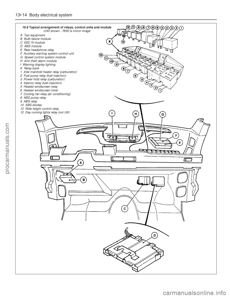
16.9 Typical arrangement of relays, control units and module
LHD shown - RHD is mirror image
A Taxi equipment
B Bulb failure module
C EEC IV module
D ABS module
E Rear headphone relay
F Auxiliary warning system control unit
G Speed control system module
H Anti-theft alarm module
I Warning display lighting
K Relay bank
1 Inlet manifold heater relay (carburettor)
2 Fuel pump relay (fuel-injection)
3 Power hold relay (carburettor)
4 Injector relay (fuel-injection)
5 Heated windscreen relay
6 Heated windscreen timer
7 Cooling fan relay (air conditioning)
8 ABS pump relay
9 ABS relay
10 ABS diodes
12 Ride height control relay
12 Day running lights relay (not UK)
procarmanuals.com
Page 195 of 255
Computer module and bulb
Models before April 1992
2Remove the instrument panel surround,
which is secured by four screws.
3Carefully pull the module from its location.
Release the multi-plug by pressing
downwards and disconnect it.
4The module illumination bulbholder may
now be extracted by gripping it with pliers and
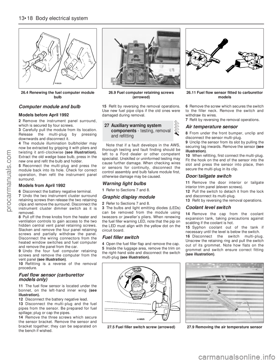
twisting it anti-clockwise (see illustration).
Extract the old wedge base bulb, press in the
new one and refit the bulb and holder.
5Reconnect the multi-plug and press the
module back into its hole. Check for correct
operation, then refit the instrument panel
surround.
Models from April 1992
6Disconnect the battery negative terminal.
7Undo the two instrument cluster surround
retaining screws then release the two retaining
clips and remove the surround. Disconnect the
instrument cluster dimmer switch as it is
removed.
8Pull off the three knobs from the heater and
ventilation controls to gain access to the two
hidden central vent panel retaining screws.
Slacken and remove the four panel retaining
screws and partially withdraw the panel.
Disconnect the wiring connectors from the
heated window switches and fuel computer
and remove the panel from the car.
9Undo the four fuel computer retaining
screws and remove the computer from the
vent panel (see illustration).
10Refitting is a reverse of the removal
procedure.
Fuel flow sensor (carburettor
models only)
11The fuel flow sensor is located under the
bonnet, on the left-hand inner wing (see
illustration).
12Disconnect the battery negative lead.
13Disconnect the multi-plug and the fuel
pipes from the sensor. Be prepared for fuel
spillage; plug or cap the pipes.
14Remove the three screws which secure
the sensor bracket. Remove the sensor and
bracket together; they can be separated on
the bench if wished.15Refit by reversing the removal operations.
Use new fuel pipe clips if the old ones were
damaged during removal.
Note that if a fault develops in the AWS,
thorough testing and fault finding should be
left to a Ford dealer or other competent
specialist. Unskilled or uninformed testing may
cause further damage. When checking wires
or sensors for continuity, disconnect the
control assembly and bulb failure module first,
otherwise damage may be caused.
Warning light bulbs
1Refer to Sections 7 and 8.
Graphic display module
2Refer to Sections 7 and 8.
3The bulbs and light emitting diodes (LEDs)
can be removed from the module using
tweezers or jeweller’s pliers. When renewing
the fuel filler warning LED, note that the pip on
the LED must align with the yellow dot on the
circuit board.
Fuel filler switch
4Open the fuel filler flap and remove the cap.
5Inside the luggage area, remove the trim on
the right-hand side and disconnect the switch
multi-plug(see illustration).6Remove the screw which secures the switch
to the filler neck. Remove the switch and
withdraw its wires.
7Refit by reversing the removal operations.
Air temperature sensor
8From under the front bumper, unclip and
disconnect the sensor multi-plug.
9Unclip the sensor from its slot by pulling the
securing tag inwards. Remove the sensor (see
illustration).
10When refitting, first connect the multi-plug.
Fit the hook on the end of the sensor into the
slot and press the sensor into place, then
secure the multi-plug in its clip.
Door/tailgate switch
11Remove the door interior ortailgate
interior trim panel (eleven screws).
12Pull the switch to detach it from the lock
and disconnect its multi-plug.
13Refit by reversing the removal operations.
Coolant level switch
14Remove the cap from the coolant
expansion tank, taking precautions against
scalding if the coolant is hot.
15Syphon coolant out of the tank if
necessary until the level is below the switch.
16Disconnect the switch multi-plug.
Unscrew the retaining ring and pull the switch
out of its grommet. Note how flats on the
grommet and switch ensure correct fitting
(see illustration).
27Auxiliary warning system
components - testing, removal
and refitting
13•18Body electrical system
26.4 Renewing the fuel computer module
bulb
27.5 Fuel filler switch screw (arrowed)27.9 Removing the air temperature sensor
26.9 Fuel computer retaining screws
(arrowed)26.11 Fuel flow sensor fitted to carburettor
models
procarmanuals.com
Page 196 of 255
17Refit by inserting the switch into the
grommet - use a new grommet if necessary -
and screwing on the retaining ring. Reconnect
the multi-plug and top-up the cooling system.
Washer fluid level switch
18Syphon the fluid out of the washer
reservoir until the level is below the switch.
19Disconnect the switch multi-plug.
Carefully prise the switch out of its grommet
and remove it. Note how flats on the grommet
and switch ensure correct fitting (see
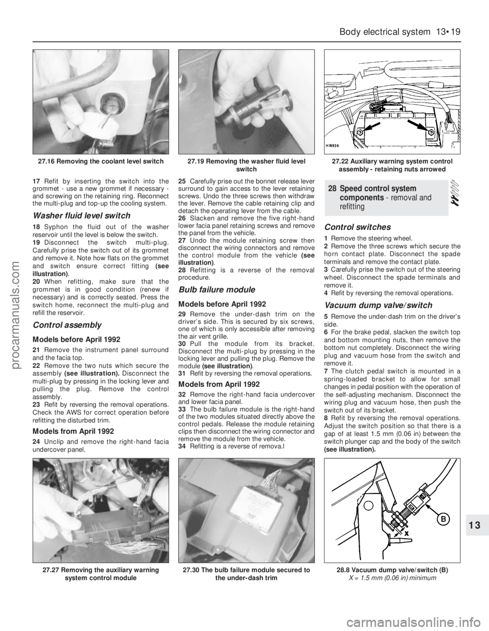
illustration).
20When refitting, make sure that the
grommet is in good condition (renew if
necessary) and is correctly seated. Press the
switch home, reconnect the multi-plug and
refill the reservoir.
Control assembly
Models before April 1992
21Remove the instrument panel surround
and the facia top.
22Remove the two nuts which secure the
assembly(see illustration).Disconnect the
multi-plug by pressing in the locking lever and
pulling the plug. Remove the control
assembly.
23Refit by reversing the removal operations.
Check the AWS for correct operation before
refitting the disturbed trim.
Models from April 1992
24Unclip and remove the right-hand facia
undercover panel.25Carefully prise out the bonnet release lever
surround to gain access to the lever retaining
screws. Undo the three screws then withdraw
the lever. Remove the cable retaining clip and
detach the operating lever from the cable.
26Slacken and remove the five right-hand
lower facia panel retaining screws and remove
the panel from the vehicle.
27Undo the module retaining screw then
disconnect the wiring connectors and remove
the control module from the vehicle (see
illustration).
28Refitting is a reverse of the removal
procedure.
Bulb failure module
Models before April 1992
29Remove the under-dash trim on the
driver’s side. This is secured by six screws,
one of which is only accessible after removing
the air vent grille.
30Pull the module from its bracket.
Disconnect the multi-plug by pressing in the
locking lever and pulling the plug. Remove the
module (see illustration).
31Refit by reversing the removal operations.
Models from April 1992
32Remove the right-hand facia undercover
and lower facia panel.
33The bulb failure module is the right-hand
of the two modules situated directly above the
control pedals. Release the module retaining
clips then disconnect the wiring connector and
remove the module from the vehicle.
34Refitting is a reverse of remova.l
Control switches
1Remove the steering wheel.
2Remove the three screws which secure the
horn contact plate. Disconnect the spade
terminals and remove the contact plate.
3Carefully prise the switch out of the steering
wheel. Disconnect the spade terminals and
remove it.
4Refit by reversing the removal operations.
Vacuum dump valve/switch
5Remove the under-dash trim on the driver’s
side.
6For the brake pedal, slacken the switch top
and bottom mounting nuts, then remove the
bottom nut completely. Disconnect the wiring
plug and vacuum hose from the switch and
remove it.
7The clutch pedal switch is mounted in a
spring-loaded bracket to allow for small
changes in pedal position with the operation of
the self-adjusting mechanism. Disconnect the
wiring plug and vacuum hose, then push the
switch out of its bracket.
8Refit by reversing the removal operations.
Adjust the switch position so that there is a
gap of at least 1.5 mm (0.06 in) between the
switch plunger cap and the body of the switch
(see illustration).
28Speed control system
components - removal and
refitting
Body electrical system 13•19
13
27.16 Removing the coolant level switch27.19 Removing the washer fluid level
switch27.22 Auxiliary warning system control
assembly - retaining nuts arrowed
27.27 Removing the auxiliary warning
system control module27.30 The bulb failure module secured to
the under-dash trim28.8 Vacuum dump valve/switch (B)
X = 1.5 mm (0.06 in) minimum
procarmanuals.com
Page 200 of 255
The components of the alarm system are a
control module, tripping switches, activating
switches, an alarm horn and a signal buzzer.
The control module is located behind the
facia. It determines whether the alarm is set or
not, monitors the tripping switches and the
ignition circuit, and limits the duration of the
alarm to 30 seconds. This last item is a legal
requirement. The control module also
operates the signal buzzer to tell the driver
that the alarm is set, and controls the activator
delay.
The tripping switches on the doors and
tailgate are the same as those used for “open
door” warnings in the AWS. The bonnet switch
is peculiar to the alarm system.
The activating switches are fitted to the
front door lock barrels, where they are
activated by a lug on the end of the barrel.
They only make contact momentarily as the
lock is operated.
The alarm horn is mounted next to the
battery. Both the horn and its leads are
claimed to be inaccessible without opening
the bonnet. The signal buzzer is also mounted
under the bonnet.
No service, repair or component renewal
procedures have been published for the alarmsystem components on earlier models. Any
problems arising which cannot be dealt with
by component substitution should therefore
be referred to a Ford dealer.
Ultrasonic sensor
1Disconnect the battery negative terminal.
2Prise out the retaining screw trim cap from
the centre of the sensor then slacken and
remove the retaining screws and lower the
sensor away from the headlining,
disconnecting the wiring plug as it becomes
accessible.
3Refitting is the reverse of the removal
procedure.
Anti-theft alarm module (models
from April 1992)
4On these models the alarm module is located
behind the righthand lower facia panel.
5To remove the module, remove the right-
hand facia undercover and lower facia panel.
6The anti-theft alarm module is the left-hand
of the two modules situated directly above the
control pedals. Release the module retaining
clips then disconnect the wiring connector and
remove the module from the vehicle (see
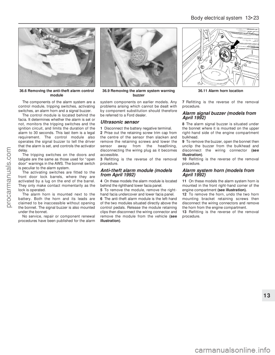
illustration).7Refitting is the reverse of the removal
procedure.
Alarm signal buzzer (models from
April 1992)
8The alarm signal buzzer is situated under
the bonnet where it is mounted on the upper
right-hand side of the engine compartment
bulkhead.
9To remove the buzzer, open the bonnet then
unclip the buzzer from the bulkhead and
disconnect the wiring connector (see
illustration).
10Refitting is the reverse of the removal
procedure.
Alarm system horn (models from
April 1992)
11On these models the alarm system horn is
mounted in the front right-hand corner of the
engine compartment (see illustration).
12To remove the horn, undo the two horn
mounting bracket retaining screws then
disconnect the wiring connectors and remove
the horn from the engine compartment.
13Refitting is the reverse of the removal
procedure.
Body electrical system 13•23
13
36.6 Removing the anti-theft alarm control
module36.9 Removing the alarm system warning
buzzer36.11 Alarm horn location
procarmanuals.com
Page 201 of 255
WD•0
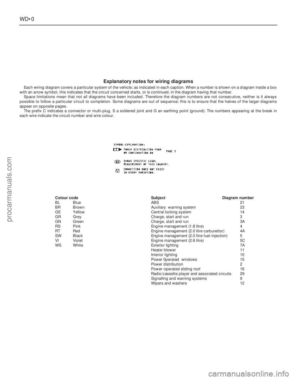
Explanatory notes for wiring diagrams
Each wiring diagram covers a particular system of the vehicle; as indicated in each caption. When a number is shown on a diagram inside a box
with an arrow symbol, this indicates that the circuit concerned starts, or is continued, in the diagram having that number.
Space limitations mean that not all diagrams have been included. Therefore the diagram numbers are not consecutive, neither is it always
possible to follow a particular circuit to completion. Some diagrams are out of sequence; this is to ensure that the halves of the larger diagrams
appear on opposite pages.
The prefix C indicates a connector or multi-plug, S a soldered joint and G an earthing point (ground). The numbers appearing at the break in
each wire indicate the circuit number and wire colour.
Colour code
BLBlue
BRBrown
GEYellow
GRGrey
GNGreen
RSPink
RT Red
SWBlack
VIViolet
WSWhiteSubjectDiagram number
ABS21
Auxiliary warning system23
Central locking system14
Charge, start and run3
Charge, start and run3A
Engine management (1.8 litre)4
Engine management (2.0 litre carburettor)4A
Engine management (2.0 litre fuel-injection)5
Engine management (2.8 litre)5C
Exterior lighting7A
Heater blower11
Interior lighting10
Power 0perated windows15
Power distribution2
Power-operated sliding roof16
Radio/cassette player and associated circuits29
Signalling and warning systems9
Wipers and washers12
procarmanuals.com
Page 219 of 255
WD•18Wiring diagrams
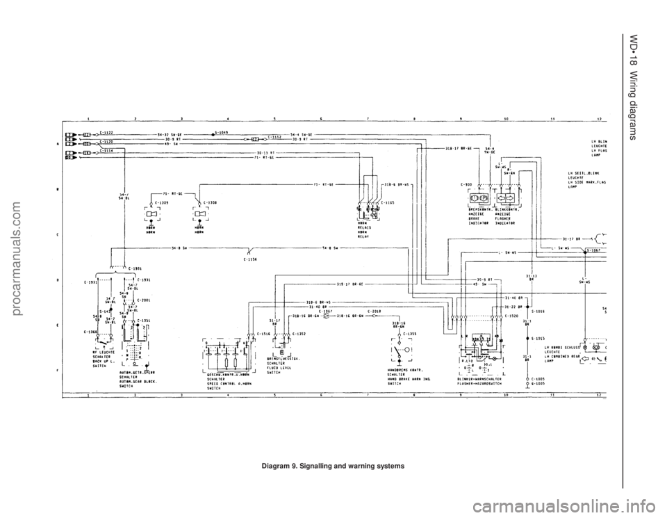
Diagram 9. Signalling and warning systems
procarmanuals.com
Page 220 of 255
Wiring diagrams WD•19
WD
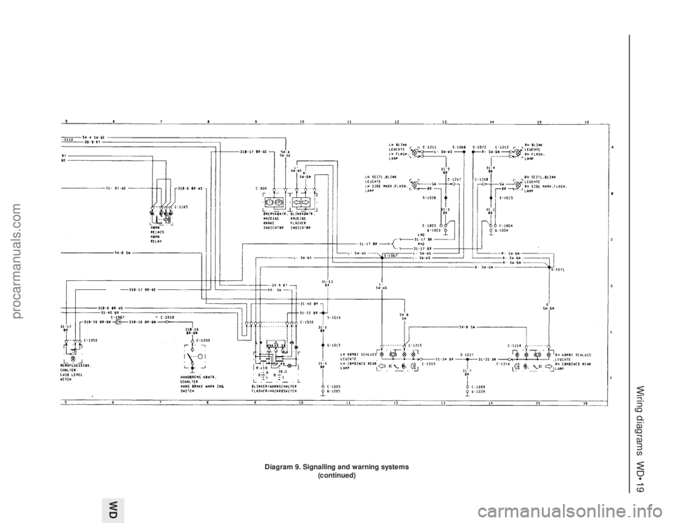
Diagram 9. Signalling and warning systems
(continued)
procarmanuals.com
Page 231 of 255
WD•30Wiring diagrams
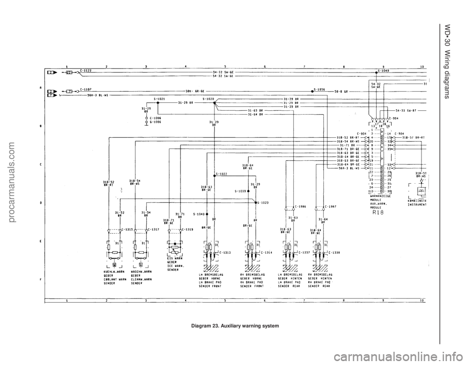
Diagram 23. Auxiliary warning system
procarmanuals.com