1985 FORD GRANADA ABS
[x] Cancel search: ABSPage 140 of 255
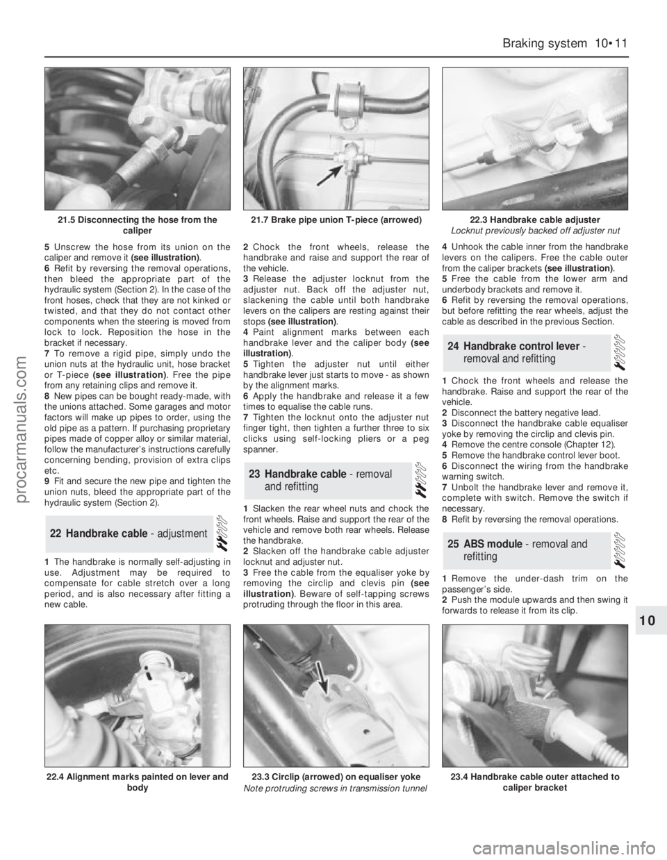
5Unscrew the hose from its union on the
caliper and remove it (see illustration).
6Refit by reversing the removal operations,
then bleed the appropriate part of the
hydraulic system (Section 2). In the case of the
front hoses, check that they are not kinked or
twisted, and that they do not contact other
components when the steering is moved from
lock to lock. Reposition the hose in the
bracket if necessary.
7To remove a rigid pipe, simply undo the
union nuts at the hydraulic unit, hose bracket
or T-piece (see illustration). Free the pipe
from any retaining clips and remove it.
8New pipes can be bought ready-made, with
the unions attached. Some garages and motor
factors will make up pipes to order, using the
old pipe as a pattern. If purchasing proprietary
pipes made of copper alloy or similar material,
follow the manufacturer’s instructions carefully
concerning bending, provision of extra clips
etc.
9Fit and secure the new pipe and tighten the
union nuts, bleed the appropriate part of the
hydraulic system (Section 2).
1The handbrake is normally self-adjusting in
use. Adjustment may be required to
compensate for cable stretch over a long
period, and is also necessary after fitting a
new cable.2Chock the front wheels, release the
handbrake and raise and support the rear of
the vehicle.
3Release the adjuster locknut from the
adjuster nut. Back off the adjuster nut,
slackening the cable until both handbrake
levers on the calipers are resting against their
stops (see illustration).
4Paint alignment marks between each
handbrake lever and the caliper body (see
illustration).
5Tighten the adjuster nut until either
handbrake lever just starts to move - as shown
by the alignment marks.
6Apply the handbrake and release it a few
times to equalise the cable runs.
7Tighten the locknut onto the adjuster nut
finger tight, then tighten a further three to six
clicks using self-locking pliers or a peg
spanner.
1Slacken the rear wheel nuts and chock the
front wheels. Raise and support the rear of the
vehicle and remove both rear wheels. Release
the handbrake.
2Slacken off the handbrake cable adjuster
locknut and adjuster nut.
3Free the cable from the equaliser yoke by
removing the circlip and clevis pin (see
illustration). Beware of self-tapping screws
protruding through the floor in this area.4Unhook the cable inner from the handbrake
levers on the calipers. Free the cable outer
from the caliper brackets (see illustration).
5Free the cable from the lower arm and
underbody brackets and remove it.
6Refit by reversing the removal operations,
but before refitting the rear wheels, adjust the
cable as described in the previous Section.
1Chock the front wheels and release the
handbrake. Raise and support the rear of the
vehicle.
2Disconnect the battery negative lead.
3Disconnect the handbrake cable equaliser
yoke by removing the circlip and clevis pin.
4Remove the centre console (Chapter 12).
5Remove the handbrake control lever boot.
6Disconnect the wiring from the handbrake
warning switch.
7Unbolt the handbrake lever and remove it,
complete with switch. Remove the switch if
necessary.
8Refit by reversing the removal operations.
1Remove the under-dash trim on the
passenger’s side.
2Push the module upwards and then swing it
forwards to release it from its clip.
25ABS module - removal and
refitting
24Handbrake control lever -
removal and refitting
23Handbrake cable - removal
and refitting
22Handbrake cable - adjustment
Braking system 10•11
10
21.5 Disconnecting the hose from the
caliper21.7 Brake pipe union T-piece (arrowed)22.3 Handbrake cable adjuster
Locknut previously backed off adjuster nut
22.4 Alignment marks painted on lever and
body23.3 Circlip (arrowed) on equaliser yoke
Note protruding screws in transmission tunnel23.4 Handbrake cable outer attached to
caliper bracket
procarmanuals.com
Page 141 of 255
3Press the multi-plug locking lever,
disconnect the multi-plug and unhook it from
the module. Remove the module.
4Refit by reversing the removal operations.
Make sure that the multi-plug is properly
engaged before refitting the module.
Front
1Ensure that the handbrake is applied. Raise
and support the front of the vehicle.
2From under the bonnet disconnect the
wheel sensor wiring multi-plug. Unclip the
wiring, working towards the sensor.
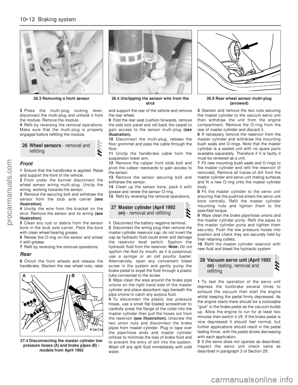
3Remove the securing bolt and withdraw the
sensor from the stub axle carrier (see
illustration).
4Unclip the wire from the bracket on the
strut. Remove the sensor and its wiring (see
illustration).
5Clean any rust or debris from the sensor
bore in the stub axle carrier. Pack the bore
with clean wheel bearing grease.
6Renew the O-ring on the sensor and smear
it with grease.
7Refit by reversing the removal operations.
Rear
8Chock the front wheels and release the
handbrake. Slacken the rear wheel nuts, raiseand support the rear of the vehicle and remove
the rear wheel.
9Fold the rear seat cushion forwards, remove
the side kick panel and roll back the carpet to
gain access to the sensor multi-plug (see
illustration).
10Disconnect the multi-plug, release the
floor grommet and pass the cable through the
floor.
11Unclip the handbrake cable from the
suspension lower arm.
12Remove the caliper front slide bolt and
pivot the caliper rearwards to gain access to
the sensor.
13Remove the sensor securing bolt and
withdraw the sensor.
14Clean up the sensor bore, pack it with
grease and renew the sensor O-ring.
15Refit by reversing the removal operations.
1Disconnect the battery negative terminal.
2Disconnect the wiring plug then remove the
master cylinder reservoir cap; do not invert the
cap as hydraulic fluid could enter and damage
the reservoir level switch. Syphon the
hydraulic fluid from the reservoir. Note: Do not
syphon the fluid by mouth, as it is poisonous;
use a syringe or an old poultry baster.
Alternatively, open any convenient bleed
screw in the system and gently pump the
brake pedal to expel the fluid through a plastic
tube connected to the screw.
3Wipe clean the area around the brake pipe
unions on the right-hand side of the master
cylinder and place absorbent rags beneath the
pipe unions to catch any surplus fluid.
4To disconnect the plastic low pressure
hoses, use a small flat bladed screwdriver to
carefully press the flange of the collet into the
master cylinder then pull the hoses out from
the reservoir(see illustration).Unscrew the
two union nuts and disconnect the brake
pipes from master cylinder. Plug or tape over
the pipe/hose ends and master cylinder
orifices to minimise the loss of brake fluid and
to prevent the entry of dirt into the system.
Wash off any spilt fluid immediately with cold
water.5Slacken and remove the two nuts securing
the master cylinder to the vacuum servo unit
then withdraw the unit from the engine
compartment. Remove the O-ring from the
rear of master cylinder and discard it.
6If necessary remove the reservoir from the
master cylinder and withdraw the mounting
bush seals and O-rings. Note that the master
cylinder is a sealed unit with no spare parts
available separately. Therefore if it is faulty it
must be renewed as a unit.
7Fit new mounting bush seals and O-rings to
the master cylinder and refit the reservoir (if
removed). Remove all traces of dirt from the
master cylinder and servo unit mating surfaces
and fit a new O-ring onto the master cylinder
body.
8Fit the master cylinder to the servo unit
ensuring that the pushrod enters the servo unit
bore centrally. Refit the master cylinder
mounting nuts and tighten them to the
specified torque.
9Wipe clean the brake pipe/hose unions and
the master cylinder ports. Refit the pipes to
the master cylinder ports and tighten them
securely. Push the low pressure hoses into
position and check they are securely held by
their retaining collets.
10Refill the master cylinder reservoir with
new fluid and bleed the hydraulic system
1To test the operation of the servo unit
depress the footbrake several times to
exhaust the vacuum then start the engine
whilst keeping the pedal firmly depressed. As
the engine starts there should be a noticeable
“give” in the brake pedal as the vacuum builds
up. Allow the engine to run for at least two
minutes then switch it off. If the brake pedal is
now depressed it should feel normal, but
further applications should result in the pedal
feeling firmer, with the pedal stroke decreasing
with each application.
2If the servo does not operate as described,
inspect the servo unit check valve as
describedin paragraph 3 of Section 29.28Vacuum servo unit (April 1992
on) - testing, removal and
refitting
27Master cylinder (April 1992
on) - removal and refitting
26Wheel sensors - removal and
refitting
10•12Braking system
26.3 Removing a front sensor
27.4 Disconnecting the master cylinder low
pressure hoses (A) and brake pipes (B) -
models from April 1992
26.4 Unclipping the sensor wire from the
strut26.9 Rear wheel sensor multi-plug
(arrowed)
procarmanuals.com
Page 142 of 255
3If the servo unit still fails to operate
satisfactorily the fault lies within the unit itself.
Repairs to the unit are not possible.
4Remove the master cylinder (Section 27).
5Disconnect the vacuum hose from the servo
unit taking care not to displace the rubber
sealing grommet. Disconnect the wiring plug
from the Pedal Travel Sensor (PTS) which is
situated on the front of the servo.
6Working from inside the vehicle, remove the
servo pushrod retaining clip from the brake
pedal. If necessary, to improve access to the
brake pedal remove the right-hand lower facia
panel .
7Slacken and remove the four nuts securing
the servo unit to the bulkhead, then return to
the engine compartment and remove the
servo unit from the vehicle. Remove the
gasket from the rear of the unit and discard it.
8Note that the vacuum servo unit is a sealed
assembly with no spare parts available
separately. Therefore if it is faulty it must be
renewed as a unit. Inspect the vacuum servo
vacuum hose sealing grommet for damage or
deterioration and renew if necessary.
9Remove all traces of dirt from the servo unit
and bulkhead mating surfaces and fit a new
gasket onto the rear of the servo.
10Manoeuvre the servo unit into position,
ensuring that the servo unit pushrod is
correctly located with the hole in the pedal.
Refit the servo unit retaining nuts and tighten
them to the specified torque setting. Secure
the pushrod in position with the retaining clip
11Carefully refit the vacuum hose to the servo
unit taking great care not to damage or displace
the sealing grommet. Reconnect the wiring
connector to the Pedal Travel Sensor (PTS).
12Refit the master cylinder as described
above. On completion start the engine and
check the operation of the servo unit.
1Disconnect the vacuum hose from the servo
unit taking care not to displace the rubber
sealing grommet.
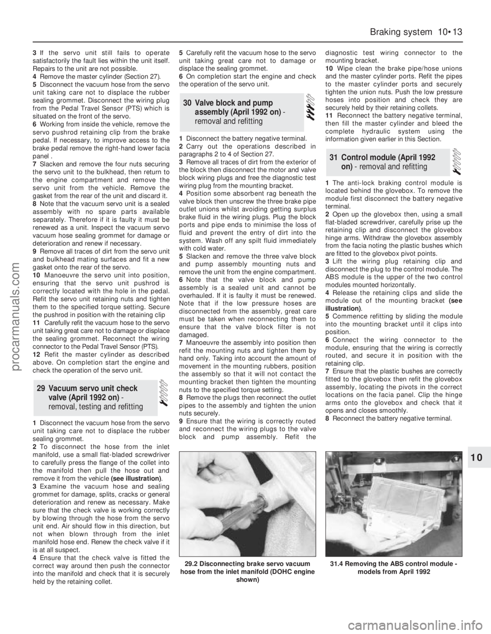
2To disconnect the hose from the inlet
manifold, use a small flat-bladed screwdriver
to carefully press the flange of the collet into
the manifold then pull the hose out and
remove it from the vehicle (see illustration).
3Examine the vacuum hose and sealing
grommet for damage, splits, cracks or general
deterioration and renew as necessary. Make
sure that the check valve is working correctly
by blowing through the hose from the servo
unit end. Air should flow in this direction, but
not when blown through from the inlet
manifold hose end. Renew the check valve if it
is at all suspect.
4Ensure that the check valve is fitted the
correct way around then push the connector
into the manifold and check that it is securely
held by the retaining collet.5Carefully refit the vacuum hose to the servo
unit taking great care not to damage or
displace the sealing grommet.
6On completion start the engine and check
the operation of the servo unit.
1Disconnect the battery negative terminal.
2Carry out the operations described in
paragraphs 2 to 4 of Section 27.
3Remove all traces of dirt from the exterior of
the block then disconnect the motor and valve
block wiring plugs and free the diagnostic test
wiring plug from the mounting bracket.
4Position some absorbent rag beneath the
valve block then unscrew the three brake pipe
outlet unions whilst avoiding getting surplus
brake fluid in the wiring plugs. Plug the block
ports and pipe ends to minimise the loss of
fluid and prevent the entry of dirt into the
system. Wash off any spilt fluid immediately
with cold water.
5Slacken and remove the three valve block
and pump assembly mounting nuts and
remove the unit from the engine compartment.
6Note that the valve block and pump
assembly is a sealed unit and cannot be
overhauled. If it is faulty it must be renewed.
Note that if the low pressure hoses are
disconnected from the assembly, great care
must be taken when reconnecting them to
ensure that the valve block filter is not
damaged.
7Manoeuvre the assembly into position then
refit the mounting nuts and tighten them by
hand only. Taking into account the amount of
movement in the mounting rubbers, position
the assembly so that it will not contact the
mounting bracket then tighten the mounting
nuts to the specified torque setting.
8Remove the plugs then reconnect the outlet
pipes to the assembly and tighten the union
nuts securely.
9Ensure that the wiring is correctly routed
and reconnect the wiring plugs to the valve
block and pump assembly. Refit thediagnostic test wiring connector to the
mounting bracket.
10Wipe clean the brake pipe/hose unions
and the master cylinder ports. Refit the pipes
to the master cylinder ports and securely
tighten the union nuts. Push the low pressure
hoses into position and check they are
securely held by their retaining collets.
11Reconnect the battery negative terminal,
then fill the master cylinder and bleed the
complete hydraulic system using the
information given earlier in this Section.
1The anti-lock braking control module is
located behind the glovebox. To remove the
module first disconnect the battery negative
terminal.
2Open up the glovebox then, using a small
flat-bladed screwdriver, carefully prise up the
retaining clip and disconnect the glovebox
hinge arms. Withdraw the glovebox assembly
from the facia noting the plastic bushes which
are fitted to the glovebox pivot points.
3Lift the wiring plug retaining clip and
disconnect the plug to the control module. The
ABS module is the upper of the two control
modules mounted horizontally.
4Release the retaining clips and slide the
module out of the mounting bracket (see
illustration).
5Commence refitting by sliding the module
into the mounting bracket until it clips into
position.
6Connect the wiring connector to the
module, ensuring that the wiring is correctly
routed, and secure it in position with the
retaining clip.
7Ensure that the plastic bushes are correctly
fitted to the glovebox then refit the glovebox
assembly, locating the pivots in the correct
locations on the facia panel. Clip the hinge
arms onto the glovebox and check that it
opens and closes smoothly.
8Reconnect the battery negative terminal.
31Control module (April 1992
on) - removal and refitting
30Valve block and pump
assembly (April 1992 on) -
removal and refitting
29 Vacuum servo unit check
valve (April 1992 on) -
removal, testing and refitting
Braking system 10•13
10
29.2 Disconnecting brake servo vacuum
hose from the inlet manifold (DOHC engine
shown)31.4 Removing the ABS control module -
models from April 1992
procarmanuals.com
Page 144 of 255
Chapter 11
Steering and suspension
Front anti-roll bar - removal and refitting . . . . . . . . . . . . . . . . . . . . .19
Front anti-roll bar bushes - renewal . . . . . . . . . . . . . . . . . . . . . . . . .20
Front stub axle carrier - removal and refitting . . . . . . . . . . . . . . . . .16
Front suspension crossmember - removal and refitting . . . . . . . . .15
Front suspension lower arm - removal, overhaul and refitting . . . . .18
Front suspension strut - dismantling and reassembly . . . . . . . . . . .22
Front suspension strut - removal and refitting . . . . . . . . . . . . . . . . .21
Front wheel alignment - checking and adjusting . . . . . . . . . . . . . . .14
Front wheel bearings - renewal . . . . . . . . . . . . . . . . . . . . . . . . . . . .17
General information . . . . . . . . . . . . . . . . . . . . . . . . . . . . . . . . . . . . . .1
Power steering fluid - level check and bleeding . . . . . . . . . . . . . . . . .2
Power steering hoses - removal and refitting . . . . . . . . . . . . . . . . . .12
Power steering pump - removal and refitting . . . . . . . . . . . . . . . . . .11
Power steering pump drivebelt - removal, refitting and tensioning .10
Rear anti-roll bar - removal and refitting . . . . . . . . . . . . . . . . . . . . .30
Rear crossmember insulator - removal and refitting . . . . . . . . . . . .28
Rear hub - removal and refitting . . . . . . . . . . . . . . . . . . . . . . . . . . . .24
Rear shock absorber - removal and refitting . . . . . . . . . . . . . . . . . .31Rear spring - removal and refitting . . . . . . . . . . . . . . . . . . . . . . . . . .27
Rear suspension and final drive assembly - removal and refitting . .23
Rear suspension lower arm - removal and refitting . . . . . . . . . . . . .29
Rear wheel bearings - renewal . . . . . . . . . . . . . . . . . . . . . . . . . . . . .25
Ride height control compressor - removal and refitting . . . . . . . . . .33
Ride height control sensor - removal and refitting . . . . . . . . . . . . . .34
Ride height control system - general information . . . . . . . . . . . . . .32
Steering column - removal and refitting . . . . . . . . . . . . . . . . . . . . . . .7
Steering column lock - removal and refitting . . . . . . . . . . . . . . . . . . .8
Steering gear - removal and refitting . . . . . . . . . . . . . . . . . . . . . . . . .3
Steering intermediate shaft and flexible coupling - removal and
refitting . . . . . . . . . . . . . . . . . . . . . . . . . . . . . . . . . . . . . . . . . . . . . .9
Steering rack bellows - renewal in vehicle . . . . . . . . . . . . . . . . . . . . .4
Steering wheel - centralising . . . . . . . . . . . . . . . . . . . . . . . . . . . . . . .6
Steering wheel - removal and refitting . . . . . . . . . . . . . . . . . . . . . . . .5
Track rod end - removal and refitting . . . . . . . . . . . . . . . . . . . . . . . .13
Wheel stud - renewal . . . . . . . . . . . . . . . . . . . . . . . . . . . . . . . . . . . .26
General
Suspension type:
Front . . . . . . . . . . . . . . . . . . . . . . . . . . . . . . . . . . . . . . . . . . . . . . . . . . Independent, MacPherson struts and anti-roll bar
Rear . . . . . . . . . . . . . . . . . . . . . . . . . . . . . . . . . . . . . . . . . . . . . . . . . . . Independent, semi-trailing arms and anti-roll bar; ride height
control optionally available
Steering type . . . . . . . . . . . . . . . . . . . . . . . . . . . . . . . . . . . . . . . . . . . . . . Rack and pinion, power-assisted on some models
Front wheel alignment
Toe:
Setting value . . . . . . . . . . . . . . . . . . . . . . . . . . . . . . . . . . . . . . . . . . . . 2 ± 1 mm (0.08 ± 0.04 in) toe-in
Tolerance in service . . . . . . . . . . . . . . . . . . . . . . . . . . . . . . . . . . . . . . 0.5 mm (0.02 in) toe-out to 4.5 mm (0.18 in) toe-in
Castor :
SOHC and 2.8 litre models:
Standard, without ride height control . . . . . . . . . . . . . . . . . . . . . . . + 1°51’ ± 1°00’
Standard, with ride height control . . . . . . . . . . . . . . . . . . . . . . . . . . + 1°58’ ± 1°00’
Heavy duty . . . . . . . . . . . . . . . . . . . . . . . . . . . . . . . . . . . . . . . . . . . + 1°46’ ± 1°00’
DOHC carburettor and low series fuel-injection models . . . . . . . . . . + 2°27’ ± 1°00’
DOHC high series models . . . . . . . . . . . . . . . . . . . . . . . . . . . . . . . . . . + 2°26’± 1°00’
2.4 litre:
low series models . . . . . . . . . . . . . . . . . . . . . . . . . . . . . . . . . . . . . . + 2°17’ ± 1°00’
high series models . . . . . . . . . . . . . . . . . . . . . . . . . . . . . . . . . . . . . + 2°50’ ± 1°00’
2.9 litre models . . . . . . . . . . . . . . . . . . . . . . . . . . . . . . . . . . . . . . . . . . + 2°22’ ± 1°00’
11•1
Easy,suitable for
novice with little
experienceFairly easy,suitable
for beginner with
some experienceFairly difficult,
suitable for competent
DIY mechanicDifficult,suitable for
experienced DIY
mechanicVery difficult,
suitable for expert
DIY or professional
Degrees of difficulty
Specifications Contents
11
procarmanuals.com
Page 146 of 255
The steering gear is of rack-and-pinion type.
Power assistance is standard on V6 models
and optional on others. The power-assisted
steering gear has a “variable ratio” effect
which increases the steering ratio about the
straight-ahead position: this provides quick
lock-to-lock action without the penalty of
over-responsiveness in open road driving.
The steering wheel is adjustable both up-
and-down and fore-and-aft. Both steering
column and shaft are designed to collapse
under impact. The steering shaft is connected
to the pinion by an intermediate shaft, which
has a universal joint at its upper end and a
flexible coupling at the lower end.
Front suspension is independent, of the
MacPherson strut type, with coil springs and
concentric telescopic shock absorbers. The
struts are attached to the tops of the stub axle
carriers, which are located at their lower ends
by balljoints incorporated in the lower
suspension arms. The lower suspension arms
pivot at their inner ends, where they are
attached to a central crossmember. The anti-
roll bar is attached to the rear of the arms and
serves to control fore-and-aft movement as
well as reducing roll.
Suspension geometry has been designed to
give good steering “feel”, resistance to pulling
caused by uneven braking effort or tyre
deflation, and (in the case of manual steering)
acceptably low steering wheel effort at parking
speeds. Only toe is adjustable in service.
The rear suspension is also independent. It
is of the semi-trailing arm type, with coil
springs and separate telescopic shock
absorbers. An optionally-available ride height
control system keeps the rear suspension
height constant, regardless of vehicle load.
Both front and rear wheel bearings are of a
special taper-roller type and require no
periodic adjustment in service.1Refer to Chapter 1, Section 35, to check the
power steering fluid level.
2If the fluid level falls so low that air enters
the pump, or after component renewal, the
system must be bled as follows.
3Remove the reservoir filler cap. Top-up with
clean fluid to the appropriate “cold” level. It is
important that the fluid is free of air bubbles,
so do not shake the container when topping-
up, and pour the fluid slowly.
4Disconnect the negative LT lead from the
ignition coil. Have an assistant crank the
engine on the starter in two second bursts, at
the same time turning the steering wheel from
lock to lock. Keep the reservoir topped up
whilst this is going on.
5When air bubbles no longer appear in the
fluid, stop the cranking. Reconnect the coil
negative lead and run the engine for a few
seconds, then stop it and check the level
again. Refit the filler cap.
6Run the vehicle for a few miles to warm up
the fluid and expel any remaining air, then stop
the engine and make a final fluid level check.
Manual steering
1Position the steering in the straight-ahead
position, then remove the ignition key so that
the steering is locked.
2Slacken the front wheel nuts. Raise and
support the front of the vehicle and remove
the front wheels.
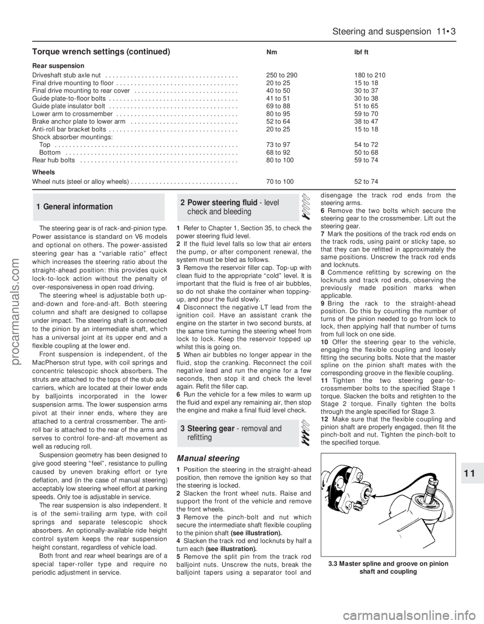
3Remove the pinch-bolt and nut which
secure the intermediate shaft flexible coupling
to the pinion shaft (see illustration).
4Slacken the track rod end locknuts by half a
turn each (see illustration).
5Remove the split pin from the track rod
balljoint nuts. Unscrew the nuts, break the
balljoint tapers using a separator tool anddisengage the track rod ends from the
steering arms.
6Remove the two bolts which secure the
steering gear to the crossmember. Lift out the
steering gear.
7Mark the positions of the track rod ends on
the track rods, using paint or sticky tape, so
that they can be refitted in approximately the
same positions. Unscrew the track rod ends
and locknuts.
8Commence refitting by screwing on the
locknuts and track rod ends, observing the
previously made position marks when
applicable.
9Bring the rack to the straight-ahead
position. Do this by counting the number of
turns of the pinion needed to go from lock to
lock, then applying half that number of turns
from full lock on one side.
10Offer the steering gear to the vehicle,
engaging the flexible coupling and loosely
fitting the securing bolts. Note that the master
spline on the pinion shaft mates with the
corresponding groove in the flexible coupling.
11Tighten the two steering gear-to-
crossmember bolts to the specified Stage 1
torque. Slacken the bolts and retighten to the
Stage 2 torque. Finally tighten the bolts
through the angle specified for Stage 3.
12Make sure that the flexible coupling and
pinion shaft are properly engaged, then fit the
pinch-bolt and nut. Tighten the pinch-bolt to
the specified torque.
3Steering gear - removal and
refitting
2Power steering fluid - level
check and bleeding1General information
Steering and suspension 11•3
11
3.3 Master spline and groove on pinion
shaft and coupling
Torque wrench settings (continued)Nmlbf ft
Rear suspension
Driveshaft stub axle nut . . . . . . . . . . . . . . . . . . . . . . . . . . . . . . . . . . . . .250 to 290180 to 210
Final drive mounting to floor . . . . . . . . . . . . . . . . . . . . . . . . . . . . . . . . . .20 to 2515 to 18
Final drive mounting to rear cover . . . . . . . . . . . . . . . . . . . . . . . . . . . . .40 to 5030 to 37
Guide plate-to-floor bolts . . . . . . . . . . . . . . . . . . . . . . . . . . . . . . . . . . . .41 to 5130 to 38
Guide plate insulator bolt . . . . . . . . . . . . . . . . . . . . . . . . . . . . . . . . . . . .69 to 8851 to 65
Lower arm to crossmember . . . . . . . . . . . . . . . . . . . . . . . . . . . . . . . . . .80 to 9559 to 70
Brake anchor plate to lower arm . . . . . . . . . . . . . . . . . . . . . . . . . . . . . .52 to 6438 to 47
Anti-roll bar bracket bolts . . . . . . . . . . . . . . . . . . . . . . . . . . . . . . . . . . . .20 to 2515 to 18
Shock absorber mountings:
Top . . . . . . . . . . . . . . . . . . . . . . . . . . . . . . . . . . . . . . . . . . . . . . . . . . .73 to 9754 to 72
Bottom . . . . . . . . . . . . . . . . . . . . . . . . . . . . . . . . . . . . . . . . . . . . . . . .68 to 9250 to 68
Rear hub bolts . . . . . . . . . . . . . . . . . . . . . . . . . . . . . . . . . . . . . . . . . . . .80 to 10059 to 74
Wheels
Wheel nuts (steel or alloy wheels) . . . . . . . . . . . . . . . . . . . . . . . . . . . . . .70 to 10052 to 74
procarmanuals.com
Page 151 of 255
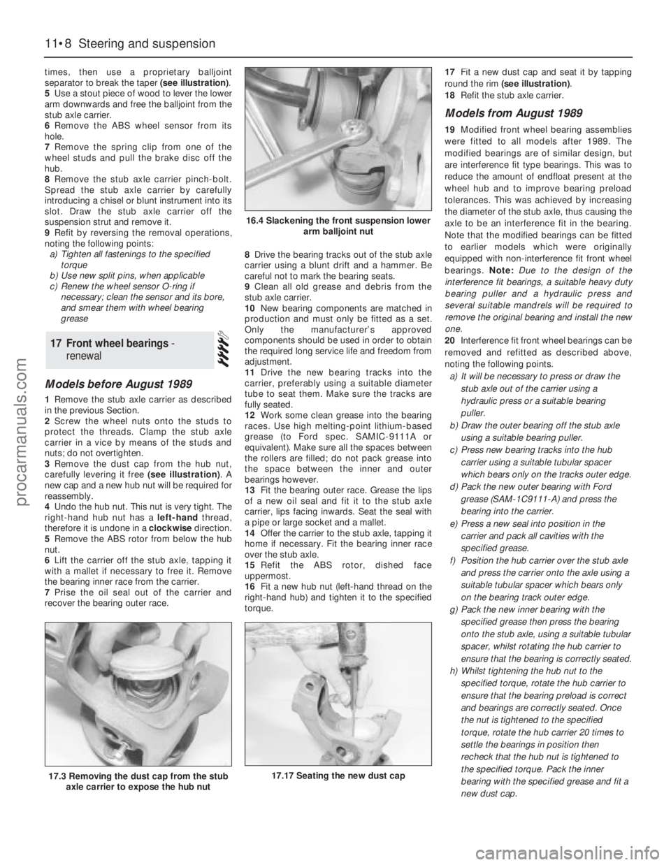
times, then use a proprietary balljoint
separator to break the taper (see illustration).
5Use a stout piece of wood to lever the lower
arm downwards and free the balljoint from the
stub axle carrier.
6Remove the ABS wheel sensor from its
hole.
7Remove the spring clip from one of the
wheel studs and pull the brake disc off the
hub.
8Remove the stub axle carrier pinch-bolt.
Spread the stub axle carrier by carefully
introducing a chisel or blunt instrument into its
slot. Draw the stub axle carrier off the
suspension strut and remove it.
9Refit by reversing the removal operations,
noting the following points:
a)Tighten all fastenings to the specified
torque
b)Use new split pins, when applicable
c)Renew the wheel sensor O-ring if
necessary; clean the sensor and its bore,
and smear them with wheel bearing
grease
Models before August 1989
1Remove the stub axle carrier as described
in the previous Section.
2Screw the wheel nuts onto the studs to
protect the threads. Clamp the stub axle
carrier in a vice by means of the studs and
nuts; do not overtighten.
3Remove the dust cap from the hub nut,
carefully levering it free (see illustration). A
new cap and a new hub nut will be required for
reassembly.
4Undo the hub nut. This nut is very tight. The
right-hand hub nut has a left-handthread,
therefore it is undone in a clockwisedirection.
5Remove the ABS rotor from below the hub
nut.
6Lift the carrier off the stub axle, tapping it
with a mallet if necessary to free it. Remove
the bearing inner race from the carrier.
7Prise the oil seal out of the carrier and
recover the bearing outer race.8Drive the bearing tracks out of the stub axle
carrier using a blunt drift and a hammer. Be
careful not to mark the bearing seats.
9Clean all old grease and debris from the
stub axle carrier.
10New bearing components are matched in
production and must only be fitted as a set.
Only the manufacturer’s approved
components should be used in order to obtain
the required long service life and freedom from
adjustment.
11Drive the new bearing tracks into the
carrier, preferably using a suitable diameter
tube to seat them. Make sure the tracks are
fully seated.
12Work some clean grease into the bearing
races. Use high melting-point lithium-based
grease (to Ford spec. SAMIC-9111A or
equivalent). Make sure all the spaces between
the rollers are filled; do not pack grease into
the space between the inner and outer
bearings however.
13Fit the bearing outer race. Grease the lips
of a new oil seal and fit it to the stub axle
carrier, lips facing inwards. Seat the seal with
a pipe or large socket and a mallet.
14Offer the carrier to the stub axle, tapping it
home if necessary. Fit the bearing inner race
over the stub axle.
15Refit the ABS rotor, dished face
uppermost.
16Fit a new hub nut (left-hand thread on the
right-hand hub) and tighten it to the specified
torque.17Fit a new dust cap and seat it by tapping
round the rim (see illustration).
18Refit the stub axle carrier.
Models from August 1989
19Modified front wheel bearing assemblies
were fitted to all models after 1989. The
modified bearings are of similar design, but
are interference fit type bearings. This was to
reduce the amount of endfloat present at the
wheel hub and to improve bearing preload
tolerances. This was achieved by increasing
the diameter of the stub axle, thus causing the
axle to be an interference fit in the bearing.
Note that the modified bearings can be fitted
to earlier models which were originally
equipped with non-interference fit front wheel
bearings. Note: Due to the design of the
interference fit bearings, a suitable heavy duty
bearing puller and a hydraulic press and
several suitable mandrels will be required to
remove the originalbearing and install the new
one.
20Interference fit front wheel bearings can be
removed and refitted as described above,
noting the following points.
a)It will be necessary to press or draw the
stub axle out of the carrier using a
hydraulic press or a suitable bearing
puller.
b)Draw the outer bearing off the stub axle
using a suitable bearing puller.
c)Press new bearing tracks into the hub
carrier using a suitable tubular spacer
which bears only on the tracks outer edge.
d)Pack the new outer bearing with Ford
grease (SAM-1C9111-A) and press the
bearing into the carrier.
e)Press a new seal into position in the
carrier and pack all cavities with the
specified grease.
f)Position the hub carrier over the stub axle
and press the carrier onto the axle using a
suitable tubular spacer which bears only
on the bearing track outer edge.
g)Pack the new inner bearing with the
specified grease then press the bearing
onto the stub axle, using a suitable tubular
spacer, whilst rotating the hub carrier to
ensure that the bearing is correctly seated.
h)Whilst tightening the hub nut to the
specified torque, rotate the hub carrier to
ensure that the bearing preload is correct
and bearings are correctly seated. Once
the nut is tightened to the specified
torque, rotate the hub carrier 20 times to
settle the bearings in position then
recheck that the hub nut is tightened to
the specified torque. Pack the inner
bearing with the specified grease and fit a
new dust cap.
17Front wheel bearings -
renewal
11•8Steering and suspension
16.4 Slackening the front suspension lower
arm balljoint nut
17.17 Seating the new dust cap17.3 Removing the dust cap from the stub
axle carrier to expose the hub nut
procarmanuals.com
Page 152 of 255
1Raise the vehicle on ramps or on a hoist, so
that the weight is still on the wheels.
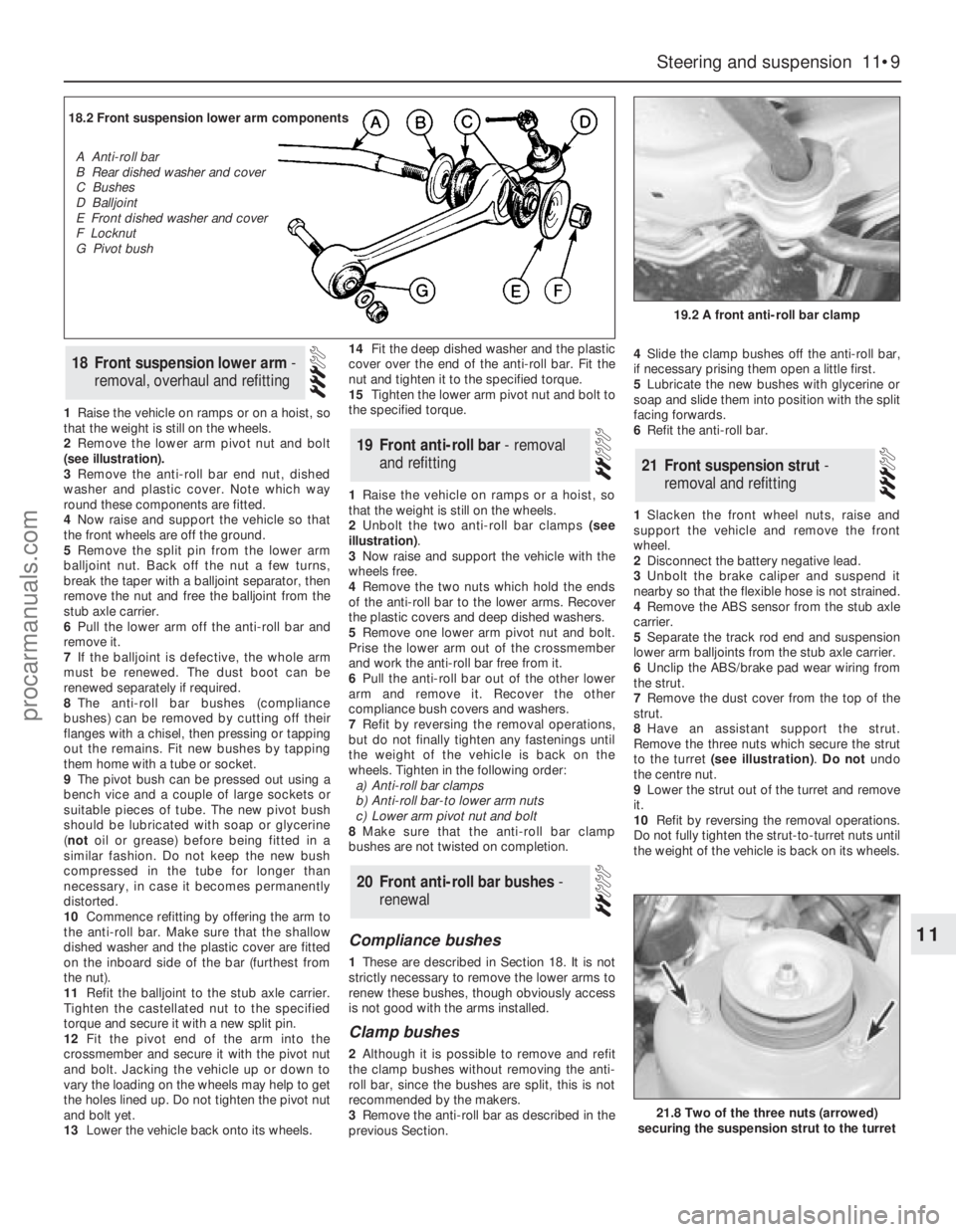
2Remove the lower arm pivot nut and bolt
(see illustration).
3Remove the anti-roll bar end nut, dished
washer and plastic cover. Note which way
round these components are fitted.
4Now raise and support the vehicle so that
the front wheels are off the ground.
5Remove the split pin from the lower arm
balljoint nut. Back off the nut a few turns,
break the taper with a balljoint separator, then
remove the nut and free the balljoint from the
stub axle carrier.
6Pull the lower arm off the anti-roll bar and
remove it.
7If the balljoint is defective, the whole arm
must be renewed. The dust boot can be
renewed separately if required.
8The anti-roll bar bushes (compliance
bushes) can be removed by cutting off their
flanges with a chisel, then pressing or tapping
out the remains. Fit new bushes by tapping
them home with a tube or socket.
9The pivot bush can be pressed out using a
bench vice and a couple of large sockets or
suitable pieces of tube. The new pivot bush
should be lubricated with soap or glycerine
(notoil or grease) before being fitted in a
similar fashion. Do not keep the new bush
compressed in the tube for longer than
necessary, in case it becomes permanently
distorted.
10Commence refitting by offering the arm to
the anti-roll bar. Make sure that the shallow
dished washer and the plastic cover are fitted
on the inboard side of the bar (furthest from
the nut).
11Refit the balljoint to the stub axle carrier.
Tighten the castellated nut to the specified
torque and secure it with a new split pin.
12Fit the pivot end of the arm into the
crossmember and secure it with the pivot nut
and bolt. Jacking the vehicle up or down to
vary the loading on the wheels may help to get
the holes lined up. Do not tighten the pivot nut
and bolt yet.
13Lower the vehicle back onto its wheels.14Fit the deep dished washer and the plastic
cover over the end of the anti-roll bar. Fit the
nut and tighten it to the specified torque.
15Tighten the lower arm pivot nut and bolt to
the specified torque.
1Raise the vehicle on ramps or a hoist, so
that the weight is still on the wheels.
2Unbolt the two anti-roll bar clamps (see
illustration).
3Now raise and support the vehicle with the
wheels free.
4Remove the two nuts which hold the ends
of the anti-roll bar to the lower arms. Recover
the plastic covers and deep dished washers.
5Remove one lower arm pivot nut and bolt.
Prise the lower arm out of the crossmember
and work the anti-roll bar free from it.
6Pull the anti-roll bar out of the other lower
arm and remove it. Recover the other
compliance bush covers and washers.
7Refit by reversing the removal operations,
but do not finally tighten any fastenings until
the weight of the vehicle is back on the
wheels. Tighten in the following order:
a)Anti-roll bar clamps
b)Anti-roll bar-to lower arm nuts
c)Lower arm pivot nut and bolt
8Make sure that the anti-roll bar clamp
bushes are not twisted on completion.
Compliance bushes
1These are described in Section 18. It is not
strictly necessary to remove the lower arms to
renew these bushes, though obviously access
is not good with the arms installed.
Clamp bushes
2Although it is possible to remove and refit
the clamp bushes without removing the anti-
roll bar, since the bushes are split, this is not
recommended by the makers.
3Remove the anti-roll bar as described in the
previous Section.4Slide the clamp bushes off the anti-roll bar,
if necessary prising them open a little first.
5Lubricate the new bushes with glycerine or
soap and slide them into position with the split
facing forwards.
6Refit the anti-roll bar.
1Slacken the front wheel nuts, raise and
support the vehicle and remove the front
wheel.
2Disconnect the battery negative lead.
3Unbolt the brake caliper and suspend it
nearby so that the flexible hose is not strained.
4Remove the ABS sensor from the stub axle
carrier.
5Separate the track rod end and suspension
lower arm balljoints from the stub axle carrier.
6Unclip the ABS/brake pad wear wiring from
the strut.
7Remove the dust cover from the top of the
strut.
8Have an assistant support the strut.
Remove the three nuts which secure the strut
to the turret (see illustration).Do notundo
the centre nut.
9Lower the strut out of the turret and remove
it.
10Refit by reversing the removal operations.
Do not fully tighten the strut-to-turret nuts until
the weight of the vehicle is back on its wheels.
21Front suspension strut -
removal and refitting
20Front anti-roll bar bushes -
renewal
19Front anti-roll bar - removal
and refitting
18Front suspension lower arm -
removal, overhaul and refitting
Steering and suspension 11•9
11
19.2 A front anti-roll bar clamp
21.8 Two of the three nuts (arrowed)
securing the suspension strut to the turret
18.2 Front suspension lower arm components
A Anti-roll bar
B Rear dished washer and cover
C Bushes
D Balljoint
E Front dished washer and cover
F Locknut
G Pivot bush
procarmanuals.com
Page 153 of 255
1With the strut removed, clamp it in a vice
with protected jaws.2Remove the stub axle carrier pinch-bolts.
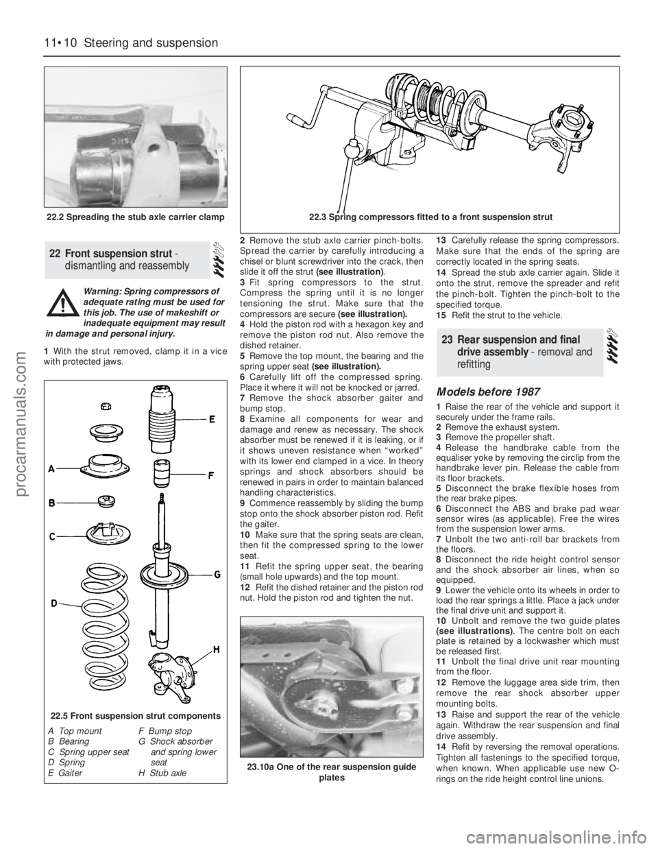
Spread the carrier by carefully introducing a
chisel or blunt screwdriver into the crack, then
slide it off the strut (see illustration).
3Fit spring compressors to the strut.
Compress the spring until it is no longer
tensioning the strut. Make sure that the
compressors are secure (see illustration).
4Hold the piston rod with a hexagon key and
remove the piston rod nut. Also remove the
dished retainer.
5Remove the top mount, the bearing and the
spring upper seat(see illustration).
6Carefully lift off the compressed spring.
Place it where it will not be knocked or jarred.
7Remove the shock absorber gaiter and
bump stop.
8Examine all components for wear and
damage and renew as necessary. The shock
absorber must be renewed if it is leaking, or if
it shows uneven resistance when “worked”
with its lower end clamped in a vice. In theory
springs and shock absorbers should be
renewed in pairs in order to maintain balanced
handling characteristics.
9Commence reassembly by sliding the bump
stop onto the shock absorber piston rod. Refit
the gaiter.
10Make sure that the spring seats are clean,
then fit the compressed spring to the lower
seat.
11Refit the spring upper seat, the bearing
(small hole upwards) and the top mount.
12Refit the dished retainer and the piston rod
nut. Hold the piston rod and tighten the nut.13Carefully release the spring compressors.
Make sure that the ends of the spring are
correctly located in the spring seats.
14Spread the stub axle carrier again. Slide it
onto the strut, remove the spreader and refit
the pinch-bolt. Tighten the pinch-bolt to the
specified torque.
15Refit the strut to the vehicle.
Models before 1987
1Raise the rear of the vehicle and support it
securely under the frame rails.
2Remove the exhaust system.
3Remove the propeller shaft.
4Release the handbrake cable from the
equaliser yoke by removing the circlip from the
handbrake lever pin. Release the cable from
its floor brackets.
5Disconnect the brake flexible hoses from
the rear brake pipes.
6Disconnect the ABS and brake pad wear
sensor wires (as applicable). Free the wires
from the suspension lower arms.
7Unbolt the two anti-roll bar brackets from
the floors.
8Disconnect the ride height control sensor
and the shock absorber air lines, when so
equipped.
9Lower the vehicle onto its wheels in order to
load the rear springs a little. Place a jack under
the final drive unit and support it.
10Unbolt and remove the two guide plates
(see illustrations). The centre bolt on each
plate is retained by a lockwasher which must
be released first.
11Unbolt the final drive unit rear mounting
from the floor.
12Remove the luggage area side trim, then
remove the rear shock absorber upper
mounting bolts.
13Raise and support the rear of the vehicle
again. Withdraw the rear suspension and final
drive assembly.
14Refit by reversing the removal operations.
Tighten all fastenings to the specified torque,
when known. When applicable use new O-
rings on the ride height control line unions.
23Rear suspension and final
drive assembly - removal and
refitting
22Front suspension strut -
dismantling and reassembly
11•10Steering and suspension
22.2 Spreading the stub axle carrier clamp22.3 Spring compressors fitted to a front suspension strut
22.5 Front suspension strut components
A Top mount
B Bearing
C Spring upper seat
D Spring
E GaiterF Bump stop
G Shock absorber
and spring lower
seat
H Stub axle
Warning: Spring compressors of
adequate rating must be used for
this job. The use of makeshift or
inadequate equipment may result
in damage and personal injury.
23.10a One of the rear suspension guide
plates
procarmanuals.com