1985 FORD GRANADA check engine
[x] Cancel search: check enginePage 142 of 255
3If the servo unit still fails to operate
satisfactorily the fault lies within the unit itself.
Repairs to the unit are not possible.
4Remove the master cylinder (Section 27).
5Disconnect the vacuum hose from the servo
unit taking care not to displace the rubber
sealing grommet. Disconnect the wiring plug
from the Pedal Travel Sensor (PTS) which is
situated on the front of the servo.
6Working from inside the vehicle, remove the
servo pushrod retaining clip from the brake
pedal. If necessary, to improve access to the
brake pedal remove the right-hand lower facia
panel .
7Slacken and remove the four nuts securing
the servo unit to the bulkhead, then return to
the engine compartment and remove the
servo unit from the vehicle. Remove the
gasket from the rear of the unit and discard it.
8Note that the vacuum servo unit is a sealed
assembly with no spare parts available
separately. Therefore if it is faulty it must be
renewed as a unit. Inspect the vacuum servo
vacuum hose sealing grommet for damage or
deterioration and renew if necessary.
9Remove all traces of dirt from the servo unit
and bulkhead mating surfaces and fit a new
gasket onto the rear of the servo.
10Manoeuvre the servo unit into position,
ensuring that the servo unit pushrod is
correctly located with the hole in the pedal.
Refit the servo unit retaining nuts and tighten
them to the specified torque setting. Secure
the pushrod in position with the retaining clip
11Carefully refit the vacuum hose to the servo
unit taking great care not to damage or displace
the sealing grommet. Reconnect the wiring
connector to the Pedal Travel Sensor (PTS).
12Refit the master cylinder as described
above. On completion start the engine and
check the operation of the servo unit.
1Disconnect the vacuum hose from the servo
unit taking care not to displace the rubber
sealing grommet.
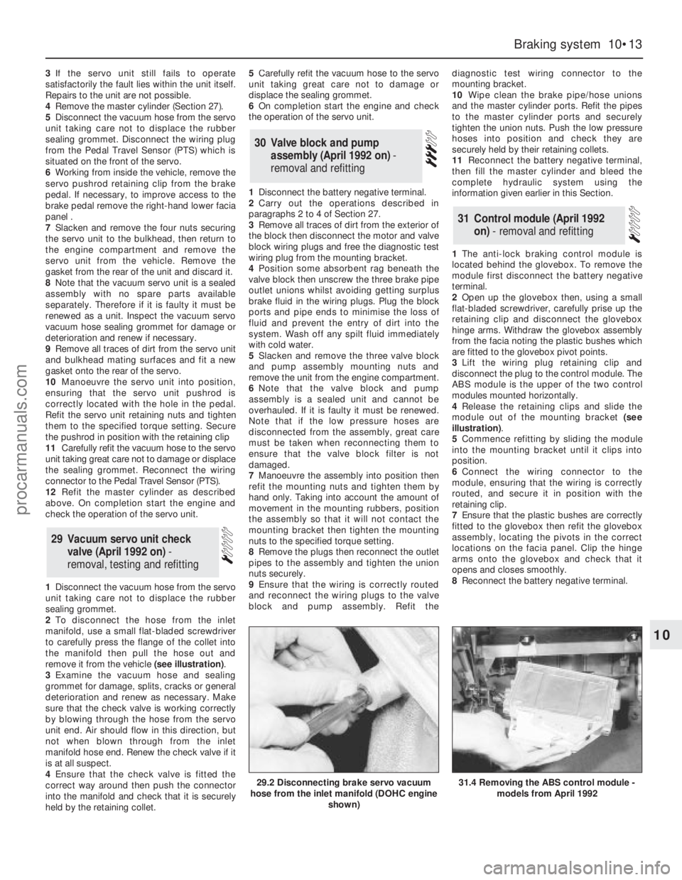
2To disconnect the hose from the inlet
manifold, use a small flat-bladed screwdriver
to carefully press the flange of the collet into
the manifold then pull the hose out and
remove it from the vehicle (see illustration).
3Examine the vacuum hose and sealing
grommet for damage, splits, cracks or general
deterioration and renew as necessary. Make
sure that the check valve is working correctly
by blowing through the hose from the servo
unit end. Air should flow in this direction, but
not when blown through from the inlet
manifold hose end. Renew the check valve if it
is at all suspect.
4Ensure that the check valve is fitted the
correct way around then push the connector
into the manifold and check that it is securely
held by the retaining collet.5Carefully refit the vacuum hose to the servo
unit taking great care not to damage or
displace the sealing grommet.
6On completion start the engine and check
the operation of the servo unit.
1Disconnect the battery negative terminal.
2Carry out the operations described in
paragraphs 2 to 4 of Section 27.
3Remove all traces of dirt from the exterior of
the block then disconnect the motor and valve
block wiring plugs and free the diagnostic test
wiring plug from the mounting bracket.
4Position some absorbent rag beneath the
valve block then unscrew the three brake pipe
outlet unions whilst avoiding getting surplus
brake fluid in the wiring plugs. Plug the block
ports and pipe ends to minimise the loss of
fluid and prevent the entry of dirt into the
system. Wash off any spilt fluid immediately
with cold water.
5Slacken and remove the three valve block
and pump assembly mounting nuts and
remove the unit from the engine compartment.
6Note that the valve block and pump
assembly is a sealed unit and cannot be
overhauled. If it is faulty it must be renewed.
Note that if the low pressure hoses are
disconnected from the assembly, great care
must be taken when reconnecting them to
ensure that the valve block filter is not
damaged.
7Manoeuvre the assembly into position then
refit the mounting nuts and tighten them by
hand only. Taking into account the amount of
movement in the mounting rubbers, position
the assembly so that it will not contact the
mounting bracket then tighten the mounting
nuts to the specified torque setting.
8Remove the plugs then reconnect the outlet
pipes to the assembly and tighten the union
nuts securely.
9Ensure that the wiring is correctly routed
and reconnect the wiring plugs to the valve
block and pump assembly. Refit thediagnostic test wiring connector to the
mounting bracket.
10Wipe clean the brake pipe/hose unions
and the master cylinder ports. Refit the pipes
to the master cylinder ports and securely
tighten the union nuts. Push the low pressure
hoses into position and check they are
securely held by their retaining collets.
11Reconnect the battery negative terminal,
then fill the master cylinder and bleed the
complete hydraulic system using the
information given earlier in this Section.
1The anti-lock braking control module is
located behind the glovebox. To remove the
module first disconnect the battery negative
terminal.
2Open up the glovebox then, using a small
flat-bladed screwdriver, carefully prise up the
retaining clip and disconnect the glovebox
hinge arms. Withdraw the glovebox assembly
from the facia noting the plastic bushes which
are fitted to the glovebox pivot points.
3Lift the wiring plug retaining clip and
disconnect the plug to the control module. The
ABS module is the upper of the two control
modules mounted horizontally.
4Release the retaining clips and slide the
module out of the mounting bracket (see
illustration).
5Commence refitting by sliding the module
into the mounting bracket until it clips into
position.
6Connect the wiring connector to the
module, ensuring that the wiring is correctly
routed, and secure it in position with the
retaining clip.
7Ensure that the plastic bushes are correctly
fitted to the glovebox then refit the glovebox
assembly, locating the pivots in the correct
locations on the facia panel. Clip the hinge
arms onto the glovebox and check that it
opens and closes smoothly.
8Reconnect the battery negative terminal.
31Control module (April 1992
on) - removal and refitting
30Valve block and pump
assembly (April 1992 on) -
removal and refitting
29 Vacuum servo unit check
valve (April 1992 on) -
removal, testing and refitting
Braking system 10•13
10
29.2 Disconnecting brake servo vacuum
hose from the inlet manifold (DOHC engine
shown)31.4 Removing the ABS control module -
models from April 1992
procarmanuals.com
Page 146 of 255
The steering gear is of rack-and-pinion type.
Power assistance is standard on V6 models
and optional on others. The power-assisted
steering gear has a “variable ratio” effect
which increases the steering ratio about the
straight-ahead position: this provides quick
lock-to-lock action without the penalty of
over-responsiveness in open road driving.
The steering wheel is adjustable both up-
and-down and fore-and-aft. Both steering
column and shaft are designed to collapse
under impact. The steering shaft is connected
to the pinion by an intermediate shaft, which
has a universal joint at its upper end and a
flexible coupling at the lower end.
Front suspension is independent, of the
MacPherson strut type, with coil springs and
concentric telescopic shock absorbers. The
struts are attached to the tops of the stub axle
carriers, which are located at their lower ends
by balljoints incorporated in the lower
suspension arms. The lower suspension arms
pivot at their inner ends, where they are
attached to a central crossmember. The anti-
roll bar is attached to the rear of the arms and
serves to control fore-and-aft movement as
well as reducing roll.
Suspension geometry has been designed to
give good steering “feel”, resistance to pulling
caused by uneven braking effort or tyre
deflation, and (in the case of manual steering)
acceptably low steering wheel effort at parking
speeds. Only toe is adjustable in service.
The rear suspension is also independent. It
is of the semi-trailing arm type, with coil
springs and separate telescopic shock
absorbers. An optionally-available ride height
control system keeps the rear suspension
height constant, regardless of vehicle load.
Both front and rear wheel bearings are of a
special taper-roller type and require no
periodic adjustment in service.1Refer to Chapter 1, Section 35, to check the
power steering fluid level.
2If the fluid level falls so low that air enters
the pump, or after component renewal, the
system must be bled as follows.
3Remove the reservoir filler cap. Top-up with
clean fluid to the appropriate “cold” level. It is
important that the fluid is free of air bubbles,
so do not shake the container when topping-
up, and pour the fluid slowly.
4Disconnect the negative LT lead from the
ignition coil. Have an assistant crank the
engine on the starter in two second bursts, at
the same time turning the steering wheel from
lock to lock. Keep the reservoir topped up
whilst this is going on.
5When air bubbles no longer appear in the
fluid, stop the cranking. Reconnect the coil
negative lead and run the engine for a few
seconds, then stop it and check the level
again. Refit the filler cap.
6Run the vehicle for a few miles to warm up
the fluid and expel any remaining air, then stop
the engine and make a final fluid level check.
Manual steering
1Position the steering in the straight-ahead
position, then remove the ignition key so that
the steering is locked.
2Slacken the front wheel nuts. Raise and
support the front of the vehicle and remove
the front wheels.
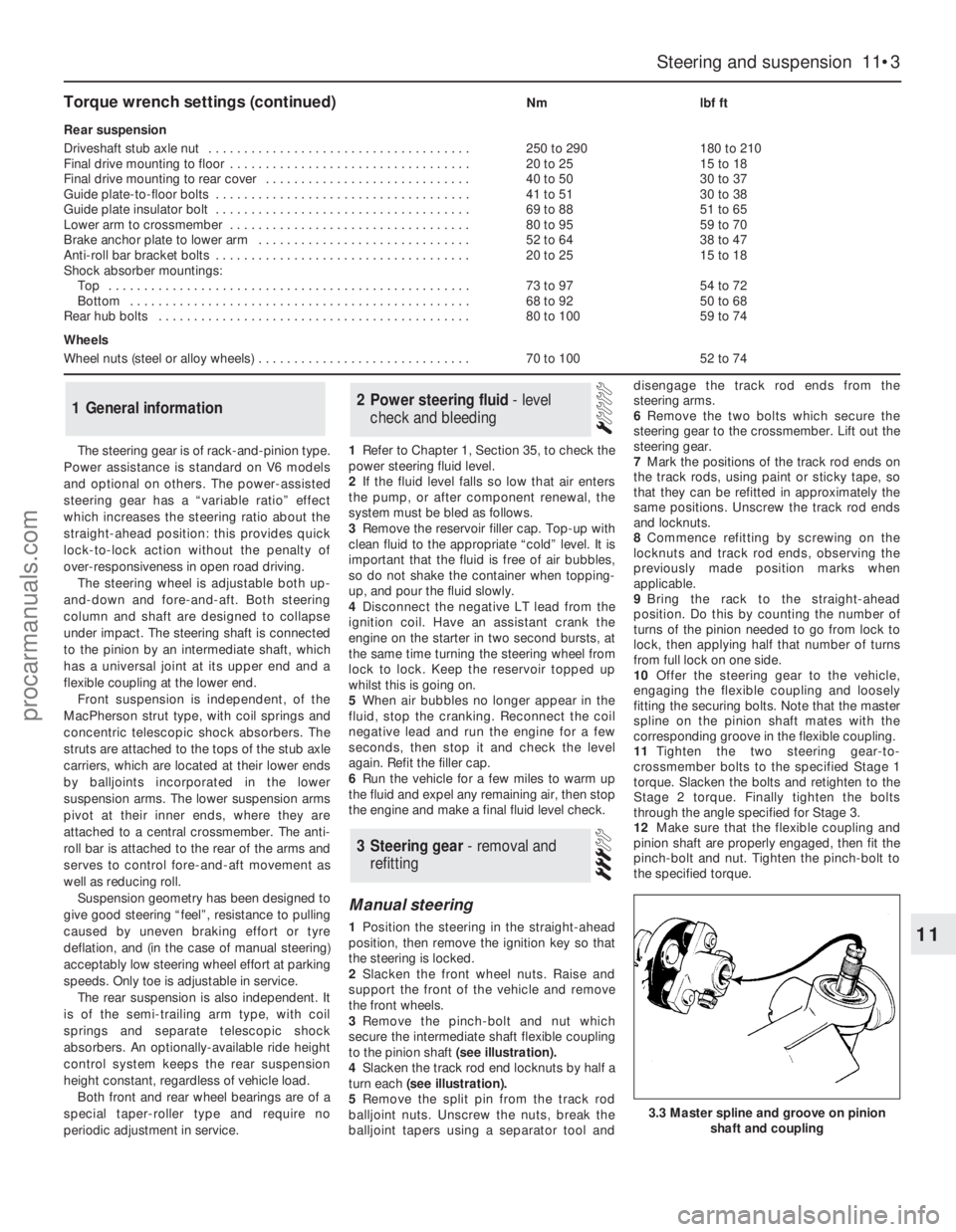
3Remove the pinch-bolt and nut which
secure the intermediate shaft flexible coupling
to the pinion shaft (see illustration).
4Slacken the track rod end locknuts by half a
turn each (see illustration).
5Remove the split pin from the track rod
balljoint nuts. Unscrew the nuts, break the
balljoint tapers using a separator tool anddisengage the track rod ends from the
steering arms.
6Remove the two bolts which secure the
steering gear to the crossmember. Lift out the
steering gear.
7Mark the positions of the track rod ends on
the track rods, using paint or sticky tape, so
that they can be refitted in approximately the
same positions. Unscrew the track rod ends
and locknuts.
8Commence refitting by screwing on the
locknuts and track rod ends, observing the
previously made position marks when
applicable.
9Bring the rack to the straight-ahead
position. Do this by counting the number of
turns of the pinion needed to go from lock to
lock, then applying half that number of turns
from full lock on one side.
10Offer the steering gear to the vehicle,
engaging the flexible coupling and loosely
fitting the securing bolts. Note that the master
spline on the pinion shaft mates with the
corresponding groove in the flexible coupling.
11Tighten the two steering gear-to-
crossmember bolts to the specified Stage 1
torque. Slacken the bolts and retighten to the
Stage 2 torque. Finally tighten the bolts
through the angle specified for Stage 3.
12Make sure that the flexible coupling and
pinion shaft are properly engaged, then fit the
pinch-bolt and nut. Tighten the pinch-bolt to
the specified torque.
3Steering gear - removal and
refitting
2Power steering fluid - level
check and bleeding1General information
Steering and suspension 11•3
11
3.3 Master spline and groove on pinion
shaft and coupling
Torque wrench settings (continued)Nmlbf ft
Rear suspension
Driveshaft stub axle nut . . . . . . . . . . . . . . . . . . . . . . . . . . . . . . . . . . . . .250 to 290180 to 210
Final drive mounting to floor . . . . . . . . . . . . . . . . . . . . . . . . . . . . . . . . . .20 to 2515 to 18
Final drive mounting to rear cover . . . . . . . . . . . . . . . . . . . . . . . . . . . . .40 to 5030 to 37
Guide plate-to-floor bolts . . . . . . . . . . . . . . . . . . . . . . . . . . . . . . . . . . . .41 to 5130 to 38
Guide plate insulator bolt . . . . . . . . . . . . . . . . . . . . . . . . . . . . . . . . . . . .69 to 8851 to 65
Lower arm to crossmember . . . . . . . . . . . . . . . . . . . . . . . . . . . . . . . . . .80 to 9559 to 70
Brake anchor plate to lower arm . . . . . . . . . . . . . . . . . . . . . . . . . . . . . .52 to 6438 to 47
Anti-roll bar bracket bolts . . . . . . . . . . . . . . . . . . . . . . . . . . . . . . . . . . . .20 to 2515 to 18
Shock absorber mountings:
Top . . . . . . . . . . . . . . . . . . . . . . . . . . . . . . . . . . . . . . . . . . . . . . . . . . .73 to 9754 to 72
Bottom . . . . . . . . . . . . . . . . . . . . . . . . . . . . . . . . . . . . . . . . . . . . . . . .68 to 9250 to 68
Rear hub bolts . . . . . . . . . . . . . . . . . . . . . . . . . . . . . . . . . . . . . . . . . . . .80 to 10059 to 74
Wheels
Wheel nuts (steel or alloy wheels) . . . . . . . . . . . . . . . . . . . . . . . . . . . . . .70 to 10052 to 74
procarmanuals.com
Page 150 of 255
6When refitting, screw the track rod end onto
the track rod as far as the locknut, then back it
off half a turn.
7Insert the ball-pin into the steering arm.
Tighten the balljoint nut to the specified torque
and secure with a new split pin. Nip up the
track rod end locknut, but do not tighten it fully
yet.
8Refit the roadwheel, lower the vehicle and
tighten the wheel nuts to the specified torque.
9Check the toe setting as described in the
following Section. (This may not be strictly
necessary if the same track rod end has been
refitted, but is certainly advisable if any
components have been renewed.)
10Tighten the track rod end locknut when
toe is correct.
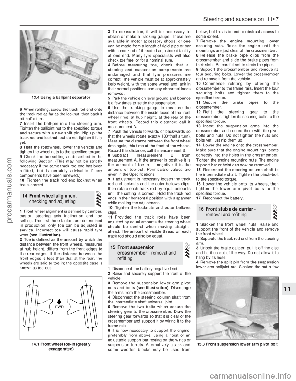
1Front wheel alignment is defined by camber,
castor, steering axis inclination and toe
setting. The first three factors are determined
in production; only toe can be adjusted in
service. Incorrect toe will cause rapid tyre
wear (see illustration).
2Toe is defined as the amount by which the
distance between the front wheels, measured
at hub height, differs from the front edges to
the rear edges. If the distance between the
front edges is less than that at the rear, the
wheels are said to toe-in; the opposite case is
known as toe-out.3To measure toe, it will be necessary to
obtain or make a tracking gauge. These are
available in motor accessory shops, or one
can be made from a length of rigid pipe or bar
with some kind of threaded adjustment facility
at one end. Many tyre specialists will also
check toe free, or for a nominal sum.
4Before measuring toe, check that all
steering and suspension components are
undamaged and that tyre pressures are
correct. The vehicle must be at approximately
kerb weight, with the spare wheel and jack in
their normal positions and any abnormal loads
removed.
5Park the vehicle on level ground and bounce
it a few times to settle the suspension.
6Use the tracking gauge to measure the
distance between the inside faces of the front
wheel rims, at hub height, at the rear of the
front wheels. Record this distance; call it
measurement A.
7Push the vehicle forwards or backwards so
that the wheels rotate exactly 180°(half a turn).
Measure the distance between the front wheel
rims again, this time at the front of the wheels.
Record this distance; call it measurement B.
8Subtract measurement B from
measurement A. If the answer is positive it is
the amount of toe-in; if negative it is the
amount of toe-out. Permissible values are
given in the Specifications.
9If adjustment is necessary loosen the track
rod end locknuts and the outer bellows clips,
then rotate each track rod by equal amounts
until the setting is correct. Hold the track rod
ends in their horizontal position with a spanner
while making the adjustment.
10Tighten the locknuts and outer bellows
clips.
11Provided the track rods have been
adjusted by equal amounts the steering wheel
should be central when moving straight-
ahead. The amount of visible thread on each
track rod should also be equal.
1Disconnect the battery negative lead.
2Raise and securely support the front of the
vehicle.
3Remove the suspension lower arm pivot
nuts and bolts (see illustration). Disengage
the arms from the crossmember.
4Disconnect the steering column shaft from
the intermediate shaft universal joint.
5Remove the two bolts which secure the
steering gear to the crossmember. Draw the
steering gear forwards so that it is clear of the
crossmember and support it by wiring it to the
frame rails.
6It is now necessary to support the engine,
preferably from above, using a hoist or an
adjustable support bar resting on the wings or
suspension turrets. Alternatively a jack and
some wooden blocks may be used frombelow, but this is bound to obstruct access to
some extent.
7Remove the engine mounting lower
securing nuts. Raise the engine until the
mountings are just clear of the crossmember.
8Release the brake pipe clips from the
crossmember and slide the brake pipes from
their slots. Be careful not to strain the pipes.
9Support the crossmember and remove its
four securing bolts. Lower the crossmember
and remove it from the vehicle.
10Commence refitting by offering the
crossmember to the frame rails. Insert the four
securing bolts and tighten them to the
specified torque.
11Secure the brake pipes to the
crossmember.
12Refit the steering gear to the
crossmember. Tighten its securing bolts to the
specified torque.
13Insert the suspension arms into the
crossmember and secure them with the pivot
bolts and nuts. Do not tighten the nuts and
bolts yet, just nip them up.
14Lower the engine onto the crossmember.
Make sure that the engine mountings locate
correctly into the holes in the crossmember.
Tighten the engine mounting nuts. The engine
support bar or hoist can now be removed.
15Reconnect the steering column shaft to
the intermediate shaft. Tighten the pinch-bolt
to the specified torque.
16Lower the vehicle onto its wheels, then
tighten the lower arm pivot bolts to the
specified torque.
17Reconnect the battery.
1Slacken the front wheel nuts. Raise and
support the front of the vehicle and remove
the front wheel.
2Separate the track rod end from the steering
arm.
3Unbolt the brake caliper, pull it off the disc
and tie it up out of the way. Do not allow it to
hang by its hose.
4Remove the split pin from the suspension
lower arm balljoint nut. Slacken the nut a few
16Front stub axle carrier -
removal and refitting
15Front suspension
crossmember - removal and
refitting
14Front wheel alignment -
checking and adjusting
Steering and suspension 11•7
11
13.4 Using a balljoint separator
14.1 Front wheel toe-in (greatly
exaggerated)15.3 Front suspension lower arm pivot bolt
procarmanuals.com
Page 159 of 255
important also to keep watch on those parts of
the vehicle not immediately visible, for
instance the underside, inside all the wheel
arches, and the lower part of the engine
compartment.
The basic maintenance routine for the
bodywork is washing - preferably with a lot of
water, from a hose. This will remove all the
loose solids which may have stuck to the
vehicle. It is important to flush these off in
such a way as to prevent grit from scratching
the finish. The wheel arches and underframe
need washing in the same way, to remove any
accumulated mud, which will retain moisture
and tend to encourage rust. Paradoxically
enough, the best time to clean the underframe
and wheel arches is in wet weather, when the
mud is thoroughly wet and soft. In very wet
weather, the underframe is usually cleaned of
large accumulations automatically, and this is
a good time for inspection.
Periodically, except on vehicles with a wax-
based underbody protective coating, it is a
good idea to have the whole of the underframe
of the vehicle steam-cleaned, engine
compartment included, so that a thorough
inspection can be carried out to see what
minor repairs and renovations are necessary.
Steam-cleaning is available at many garages,
and is necessary for the removal of the
accumulation of oily grime, which sometimes
is allowed to become thick in certain areas. If
steam-cleaning facilities are not available,
there are some excellent grease solvents
available which can be brush-applied; the dirt
can then be simply hosed off. Note that these
methods should not be used on vehicles with
wax-based underbody protective coating, or
the coating will be removed. Such vehicles
should be inspected annually, preferably just
prior to Winter, when the underbody should be
washed down, and any damage to the wax
coating repaired. Ideally, a completely fresh
coat should be applied. It would also be worth
considering the use of such wax-based
protection for injection into door panels, sills,
box sections, etc, as an additional safeguard
against rust damage, where such protection is
not provided by the vehicle manufacturer.
After washing paintwork, wipe off with a
chamois leather to give an unspotted clear
finish. A coat of clear protective wax polish will
give added protection against chemical
pollutants in the air. If the paintwork sheen has
dulled or oxidised, use a cleaner/polisher
combination to restore the brilliance of the
shine. This requires a little effort, but such
dulling is usually caused because regular
washing has been neglected. Care needs to
be taken with metallic paintwork, as special
non-abrasive cleaner/polisher is required to
avoid damage to the finish. Always check that
the door and ventilator opening drain holes
and pipes are completely clear, so that water
can be drained out. Brightwork should be
treated in the same way as paintwork.
Windscreens and windows can be kept clear
of the smeary film which often appears, by theuse of proprietary glass cleaner. Never use
any form of wax or other body or chromium
polish on glass.
Mats and carpets should be brushed or
vacuum-cleaned regularly, to keep them free
of grit. If they are badly stained, remove them
from the vehicle for scrubbing or sponging,
and make quite sure they are dry before
refitting. Seats and interior trim panels can be
kept clean by wiping with a damp cloth. If they
do become stained (which can be more
apparent on light-coloured upholstery), use a
little liquid detergent and a soft nail brush to
scour the grime out of the grain of the material.
Do not forget to keep the headlining clean in
the same way as the upholstery. When using
liquid cleaners inside the vehicle, do not over-
wet the surfaces being cleaned. Excessive
damp could get into the seams and padded
interior, causing stains, offensive odours or
even rot. If the inside of the vehicle gets wet
accidentally, it is worthwhile taking some
trouble to dry it out properly, particularly
where carpets are involved. Do not leave oil or
electric heaters inside the vehicle for this
purpose.
Repairs of minor scratches in
bodywork
If the scratch is very superficial, and does
not penetrate to the metal of the bodywork,
repair is very simple. Lightly rub the area of the
scratch with a paintwork renovator, or a very
fine cutting paste, to remove loose paint from
the scratch, and to clear the surrounding
bodywork of wax polish. Rinse the area with
clean water.
Apply touch-up paint to the scratch using a
fine paint brush; continue to apply fine layers
of paint until the surface of the paint in the
scratch is level with the surrounding
paintwork. Allow the new paint at least two
weeks to harden, then blend it into the
surrounding paintwork by rubbing the scratch
area with a paintwork renovator or a very fine
cutting paste. Finally, apply wax polish.
Where the scratch has penetrated right
through to the metal of the bodywork, causing
the metal to rust, a different repair technique is
required. Remove any loose rust from the
bottom of the scratch with a penknife, then
apply rust-inhibiting paint to prevent the
formation of rust in the future. Using a rubber
or nylon applicator, fill the scratch with
bodystopper paste. If required, this paste can
be mixed with cellulose thinners to provide a
very thin paste which is ideal for filling narrow
scratches. Before the stopper-paste in the
scratch hardens, wrap a piece of smoothcotton rag around the top of a finger. Dip the
finger in cellulose thinners, and quickly sweep
it across the surface of the stopper-paste in
the scratch; this will ensure that the surface of
the stopper-paste is slightly hollowed. The
scratch can now be painted over as described
earlier in this Section.
Repairs of dents in bodywork
When deep denting of the vehicle’s
bodywork has taken place, the first task is to
pull the dent out, until the affected bodywork
almost attains its original shape. There is little
point in trying to restore the original shape
completely, as the metal in the damaged area
will have stretched on impact, and cannot be
reshaped fully to its original contour. It is
better to bring the level of the dent up to a
point which is about 3 mm below the level of
the surrounding bodywork. In cases where the
dent is very shallow anyway, it is not worth
trying to pull it out at all. If the underside of the
dent is accessible, it can be hammered out
gently from behind, using a mallet with a
wooden or plastic head. Whilst doing this,
hold a suitable block of wood firmly against
the outside of the panel, to absorb the impact
from the hammer blows and thus prevent a
large area of the bodywork from being “belled-
out”.
Should the dent be in a section of the
bodywork which has a double skin, or some
other factor making it inaccessible from
behind, a different technique is called for. Drill
several small holes through the metal inside
the area - particularly in the deeper section.
Then screw long self-tapping screws into the
holes, just sufficiently for them to gain a good
purchase in the metal. Now the dent can be
pulled out by pulling on the protruding heads
of the screws with a pair of pliers.
The next stage of the repair is the removal
of the paint from the damaged area, and from
an inch or so of the surrounding “sound”
bodywork. This is accomplished most easily
by using a wire brush or abrasive pad on a
power drill, although it can be done just as
effectively by hand, using sheets of abrasive
paper. To complete the preparation for filling,
score the surface of the bare metal with a
screwdriver or the tang of a file, or
alternatively, drill small holes in the affected
area. This will provide a really good “key” for
the filler paste.
To complete the repair, see the Section on
filling and respraying.
Repairs of rust holes or gashes in
bodywork
Remove all paint from the affected area, and
from an inch or so of the surrounding “sound”
bodywork, using an abrasive pad or a wire
brush on a power drill. If these are not
available, a few sheets of abrasive paper will
do the job most effectively. With the paint
removed, you will be able to judge the severity
of the corrosion, and therefore decide whether
to renew the whole panel (if this is possible) or
4Minor body damage - repair
3Maintenance - upholstery and
carpets
12•2Bodywork and fittings
procarmanuals.com
Page 161 of 255
Where serious damage has occurred or
large areas need renewal due to neglect, it
means certainly that completely new sections
or panels will need welding in and this is best
left to professionals. If the damage is due to
impact, it will also be necessary to completely
check the alignment of the bodyshell
structure. Due to the principle of construction,
the strength and shape of the whole car can
be affected by damage to one part. In such
instances the services of a Ford agent with
specialist checking jigs are essential. If a body
is left misaligned, it is first of all dangerous as
the car will not handle properly, and secondly
uneven stresses will be imposed on the
steering, engine and transmission, causing
abnormal wear or complete failure. Tyre wear
may also be excessive.
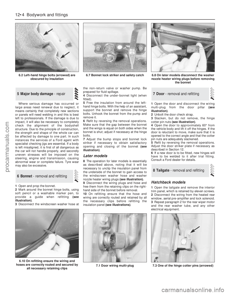
1Open and prop the bonnet.
2Mark around the bonnet hinge bolts, using
soft pencil or a washable marker pen, to
provide a guide when refitting (see
illustration).
3Disconnect the windscreen washer hose atthe non-return valve or washer pump. Be
prepared for fluid spillage.
4Disconnect the under-bonnet light (when
fitted).
5Free the insulation from around the left-
hand hinge bolts. With the help of an assistant,
support the bonnet and remove the hinge
bolts. Unhook the bonnet from the pump and
remove it.
6Refit by reversing the removal operations.
Make sure that the gap between the bonnet
and the wings is equal on both sides when the
bonnet is shut; adjust if necessary at the hinge
bolts.
7Adjust the bump stops and bonnet lock
striker if necessary to obtain satisfactory
opening and closing of the bonnet (see
illustration).
Later models
8The operation for later models is essentially
as described above, noting thatit will be
necessary to unclip the insulation panel from
the underside of the bonnet to gain access to
the windscreen washer hose and washer
nozzle heater wiring plugs (see illustration).
9Disconnect the wiring plugs and hose and
free them from the retaining clips on the right-
hand side of the bonnet before removal.
10On refitting ensure that the hose and
wiring are correctly routed and retained by all
the necessary clips before refitting the
insulation panel (see illustrations).1Open the door and disconnect the wiring
multi-plug from the door pillar (see
illustration).
2Unbolt the door check strap.
3Slacken, but do not remove, the hinge
cotter pin nuts (see illustration).
4Open the door to approximately 60°from
the vehicle body and lift it off the hinges. If the
door is reluctant to move, make sure that it is
opened to the correct angle and that the cotter
pin nuts are adequately slackened.
5Refit by reversing the removal operations.
Adjust the door striker plate if necessary as
described in Section 12.
6If a new door is to be fitted, new hinges will
have to be welded to it after trial fitting.
Consult a Ford dealer for details.
Hatchback models
1Open the tailgate and remove the interior
trim panel, which is retained by eleven screws.
2Disconnect the wiring from the heated rear
window, aerial pre-amplifier and lock solenoid.
3Repeat paragraph 2 for the rear wiper motor
and the rear washer tube, and any other
electrical equipment.
8Tailgate - removal and refitting
7Door - removal and refitting
6Bonnet - removal and refitting
5Major body damage - repair
12•4Bodywork and fittings
6.2 Left-hand hinge bolts (arrowed) are
obscured by insulation
6.10 On refitting ensure the wiring and
hoses are correctly routed and secured by
all necessary retaining clips
7.1 Door wiring multi-plug7.3 One of the hinge cotter pins (arrowed)
6.7 Bonnet lock striker and safety catch6.8 On later models disconnect the washer
nozzle heater wiring plugs before removing
the bonnet
procarmanuals.com
Page 163 of 255
3Apply masking tape to the front and sides of
the roof aperture to protect the paintwork.
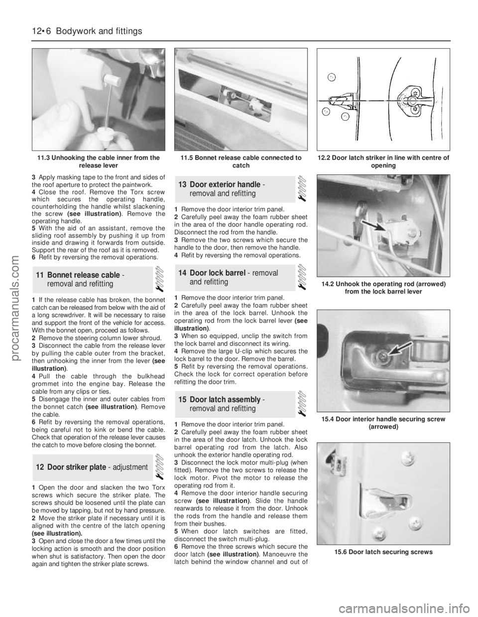
4Close the roof. Remove the Torx screw
which secures the operating handle,
counterholding the handle whilst slackening
the screw (see illustration). Remove the
operating handle.
5With the aid of an assistant, remove the
sliding roof assembly by pushing it up from
inside and drawing it forwards from outside.
Support the rear of the roof as it is removed.
6Refit by reversing the removal operations.
1If the release cable has broken, the bonnet
catch can be released from below with the aid of
a long screwdriver. It will be necessary to raise
and support the front of the vehicle for access.
With the bonnet open, proceed as follows.
2Remove the steering column lower shroud.
3Disconnect the cable from the release lever
by pulling the cable outer from the bracket,
then unhooking the inner from the lever (see
illustration).
4Pull the cable through the bulkhead
grommet into the engine bay. Release the
cable from any clips or ties.
5Disengage the inner and outer cables from
the bonnet catch (see illustration). Remove
the cable.
6Refit by reversing the removal operations,
being careful not to kink or bend the cable.
Check that operation of the release lever causes
the catch to move before closing the bonnet.
1Open the door and slacken the two Torx
screws which secure the striker plate. The
screws should be loosened until the plate can
be moved by tapping, but not by hand pressure.
2Move the striker plate if necessary until it is
aligned with the centre of the latch opening
(see illustration).
3Open and close the door a few times until the
locking action is smooth and the door position
when shut is satisfactory. Then open the door
again and tighten the striker plate screws.1Remove the door interior trim panel.
2Carefully peel away the foam rubber sheet
in the area of the door handle operating rod.
Disconnect the rod from the handle.
3Remove the two screws which secure the
handle to the door, then remove the handle.
4Refit by reversing the removal operations.
1Remove the door interior trim panel.
2Carefully peel away the foam rubber sheet
in the area of the lock barrel. Unhook the
operating rod from the lock barrel lever (see
illustration).
3When so equipped, unclip the switch from
the lock barrel and disconnect its wiring.
4Remove the large U-clip which secures the
lock barrel to the door. Remove the barrel.
5Refit by reversing the removal operations.
Check the lock for correct operation before
refitting the door trim.
1Remove the door interior trim panel.
2Carefully peel away the foam rubber sheet
in the area of the door latch. Unhook the lock
barrel operating rod from the latch. Also
unhook the exterior handle operating rod.
3Disconnect the lock motor multi-plug (when
fitted). Remove the two screws to release the
lock motor. Pivot the motor to release the
operating rod from it.
4Remove the door interior handle securing
screw (see illustration). Slide the handle
rearwards to release it from the door. Unhook
the rods from the handle and release them
from their bushes.
5When door latch switches are fitted,
disconnect the switch multi-plug.
6Remove the three screws which secure the
door latch (see illustration). Manoeuvre the
latch behind the window channel and out of
15Door latch assembly -
removal and refitting
14Door lock barrel - removal
and refitting
13Door exterior handle -
removal and refitting
12Door striker plate - adjustment
11Bonnet release cable -
removal and refitting
12•6Bodywork and fittings
11.3 Unhooking the cable inner from the
release lever
14.2 Unhook the operating rod (arrowed)
from the lock barrel lever
15.4 Door interior handle securing screw
(arrowed)
15.6 Door latch securing screws
11.5 Bonnet release cable connected to
catch12.2 Door latch striker in line with centre of
opening
procarmanuals.com
Page 181 of 255
the circuit between the relevant connector and
the battery is problem-free.
13Continue to check the remainder of the
circuit in the same fashion.
14When a point is reached at which no
voltage is present, the problem must lie
between that point and the previous test point
with voltage. Most problems can be traced to
a broken, corroded or loose connection.
Finding a short-circuit
15To check for a short-circuit, first disconnect
the load(s) from the circuit (loads are the
components which draw current from a circuit,
such as bulbs, motors, heating elements, etc).
16Remove the relevant fuse from the circuit,
and connect a circuit tester or voltmeter to the
fuse connections.
17Switch on the circuit, bearing in mind that
some circuits are live only when the ignition
switch is moved to a particular position.
18If voltage is present (indicated either by
the tester bulb lighting or a voltmeter reading),
this means that there is a short-circuit.
19If no voltage is present, but the fuse still
blows with the load(s) connected, this
indicates an internal fault in the load(s).
Finding an earth fault
20The battery negative terminal is connected
to “earth” - the metal of the engine/transmission
and the car body - and most systems are wired
so that they only receive a positive feed, the
current returning via the metal of the car body.
This means that the component mounting andthe body form part of that circuit. Loose or
corroded mountings can therefore cause a range
of electrical faults, ranging from total failure of a
circuit, to a puzzling partial fault. In particular,
lights may shine dimly (especially when another
circuit sharing the same earth is in operation),
motors (eg wiper motors or the radiator cooling
fan motor) may run slowly, and the operation of
one circuit may have an apparently-unrelated
effect on another. Note that on many vehicles,
earth straps are used between certain
components, such as the engine/transmission
and the body, usually where there is no metal-to-
metal contact between components, due to
flexible rubber mountings, etc.
21To check whether a component is properly
earthed, disconnect the battery, and connect
one lead of an ohmmeter to a known good
earth point. Connect the other lead to the wire
or earth connection being tested. The
resistance reading should be zero; if not,
check the connection as follows.
22If an earth connection is thought to be
faulty, dismantle the connection, and clean
back to bare metal both the bodyshell and the
wire terminal, or the component’s earth
connection mating surface. Be careful to
remove all traces of dirt and corrosion, then
use a knife to trim away any paint, so that a
clean metal-to-metal joint is made. On
reassembly, tighten the joint fasteners
securely; if a wire terminal is being refitted, use
serrated washers between the terminal and
the bodyshell, to ensure a clean and secure
connection. When the connection is remade,
prevent the onset of corrosion in the future byapplying a coat of petroleum jelly or silicone-
based grease, or by spraying on (at regular
intervals) a proprietary ignition sealer, or a
water-dispersant lubricant.
Headlight
1Open and prop the bonnet. Remove the
cover from the rear of the headlight unit by
twisting it anti-clockwise.
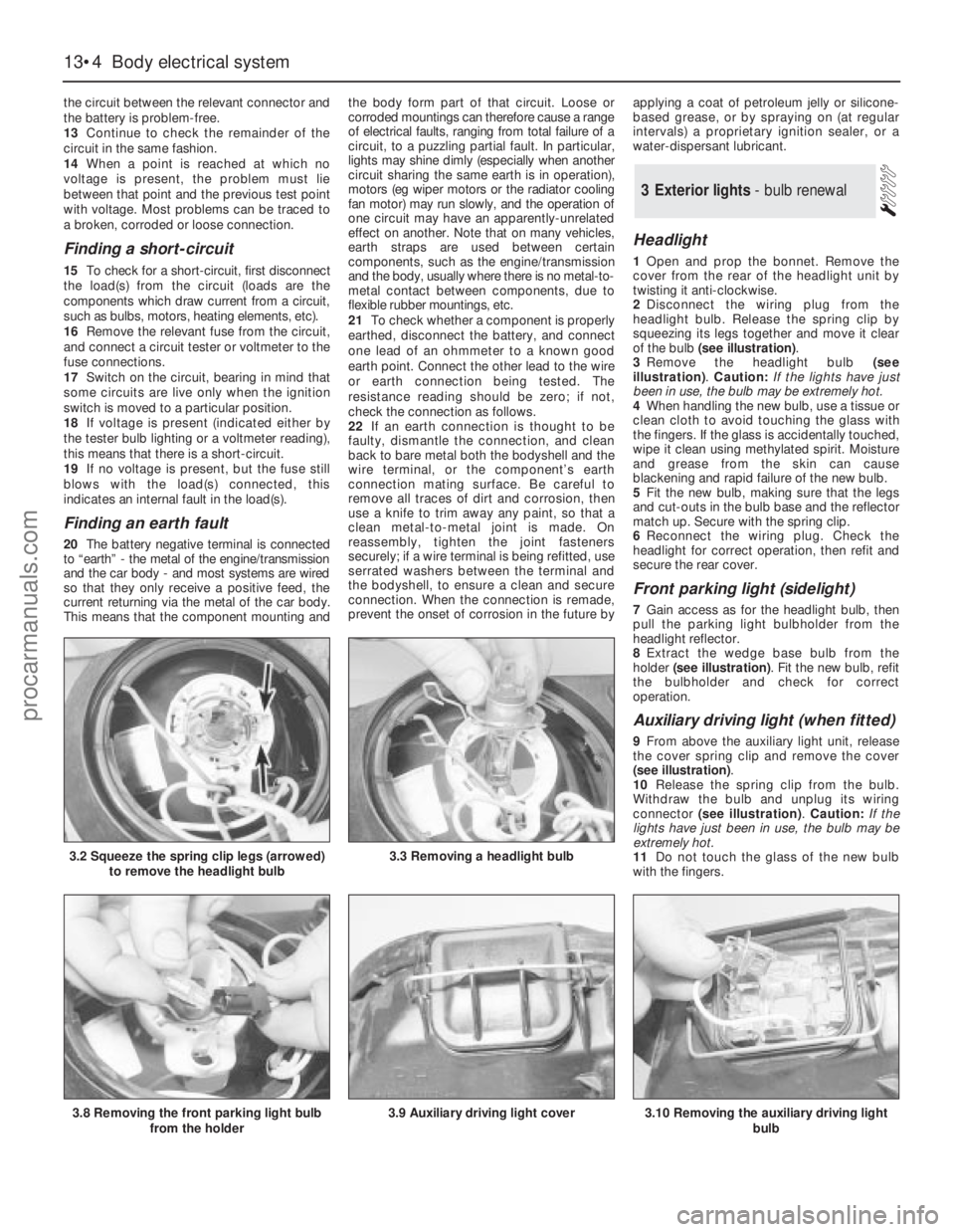
2Disconnect the wiring plug from the
headlight bulb. Release the spring clip by
squeezing its legs together and move it clear
of the bulb (see illustration).
3Remove the headlight bulb (see
illustration). Caution: If the lights have just
been in use, the bulb may be extremely hot.
4When handling the new bulb, use a tissue or
clean cloth to avoid touching the glass with
the fingers. If the glass is accidentally touched,
wipe it clean using methylated spirit. Moisture
and grease from the skin can cause
blackening and rapid failure of the new bulb.
5Fit the new bulb, making sure that the legs
and cut-outs in the bulb base and the reflector
match up. Secure with the spring clip.
6Reconnect the wiring plug. Check the
headlight for correct operation, then refit and
secure the rear cover.
Front parking light (sidelight)
7Gain access as for the headlight bulb, then
pull the parking light bulbholder from the
headlight reflector.
8Extract the wedge base bulb from the
holder (see illustration). Fit the new bulb, refit
the bulbholder and check for correct
operation.
Auxiliary driving light (when fitted)
9From above the auxiliary light unit, release
the cover spring clip and remove the cover
(see illustration).
10Release the spring clip from the bulb.
Withdraw the bulb and unplug its wiring
connector (see illustration). Caution: If the
lights have just been in use, the bulb may be
extremely hot.
11Do not touch the glass of the new bulb
with the fingers.
3Exterior lights - bulb renewal
13•4Body electrical system
3.2 Squeeze the spring clip legs (arrowed)
to remove the headlight bulb3.3 Removing a headlight bulb
3.8 Removing the front parking light bulb
from the holder3.9 Auxiliary driving light cover3.10 Removing the auxiliary driving light
bulb
procarmanuals.com
Page 185 of 255
Footwell lights
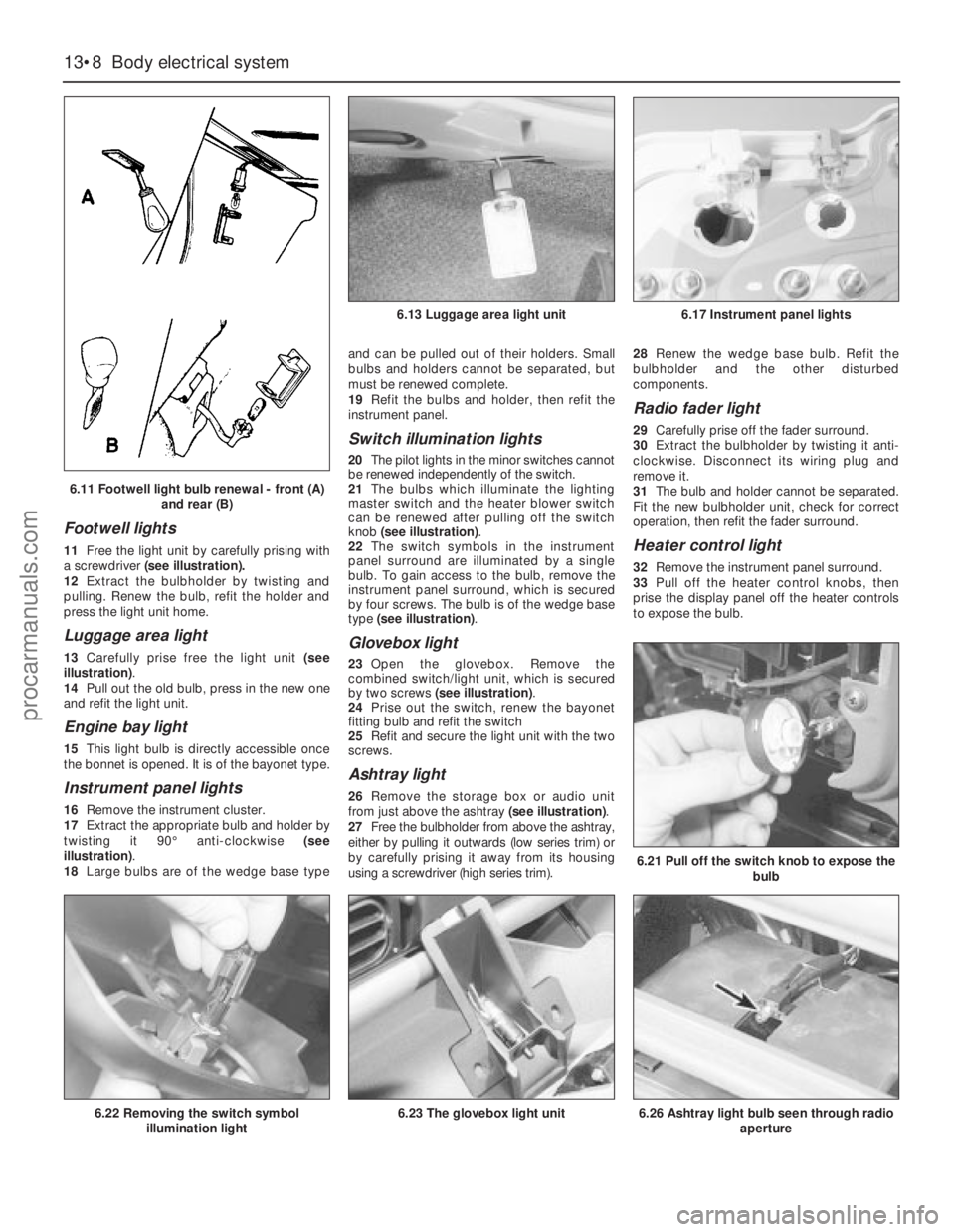
11Free the light unit by carefully prising with
a screwdriver(see illustration).
12Extract the bulbholder by twisting and
pulling. Renew the bulb, refit the holder and
press the light unit home.
Luggage area light
13Carefully prise free the light unit (see
illustration).
14Pull out the old bulb, press in the new one
and refit the light unit.
Engine bay light
15This light bulb is directly accessible once
the bonnet is opened. It is of the bayonet type.
Instrument panel lights
16Remove the instrument cluster.
17Extract the appropriate bulb and holder by
twisting it 90°anti-clockwise (see
illustration).
18Large bulbs are of the wedge base typeand can be pulled out of their holders. Small
bulbs and holders cannot be separated, but
must be renewed complete.
19Refit the bulbs and holder, then refit the
instrument panel.
Switch illumination lights
20The pilot lights in the minor switches cannot
be renewed independently of the switch.
21The bulbs which illuminate the lighting
master switch and the heater blower switch
can be renewed after pulling off the switch
knob (see illustration).
22The switch symbols in the instrument
panel surround are illuminated by a single
bulb. To gain access to the bulb, remove the
instrument panel surround, which is secured
by four screws. The bulb is of the wedge base
type (see illustration).
Glovebox light
23Open the glovebox. Remove the
combined switch/light unit, which is secured
by two screws (see illustration).
24Prise out the switch, renew the bayonet
fitting bulb and refit the switch
25Refit and secure the light unit with the two
screws.
Ashtray light
26Remove the storage box or audio unit
from just above the ashtray (see illustration).
27Free the bulbholder from above the ashtray,
either by pulling it outwards (low series trim) or
by carefully prising it away from its housing
using a screwdriver (high series trim).28Renew the wedge base bulb. Refit the
bulbholder and the other disturbed
components.
Radio fader light
29Carefully prise off the fader surround.
30Extract the bulbholder by twisting it anti-
clockwise. Disconnect its wiring plug and
remove it.
31The bulb and holder cannot be separated.
Fit the new bulbholder unit, check for correct
operation, then refit the fader surround.
Heater control light
32Remove the instrument panel surround.
33Pull off the heater control knobs, then
prise the display panel off the heater controls
to expose the bulb.
13•8Body electrical system
6.21 Pull off the switch knob to expose the
bulb
6.26 Ashtray light bulb seen through radio
aperture6.22 Removing the switch symbol
illumination light6.23 The glovebox light unit
6.13 Luggage area light unit6.17 Instrument panel lights
6.11 Footwell light bulb renewal - front (A)
and rear (B)
procarmanuals.com